wiper fluid DODGE RAM 2002 Service User Guide
[x] Cancel search | Manufacturer: DODGE, Model Year: 2002, Model line: RAM, Model: DODGE RAM 2002Pages: 2255, PDF Size: 62.07 MB
Page 654 of 2255
COOLING - STANDARD PROCEDURE - DRAIN/
DIESEL ENGINE).
(3) Disconnect the upper radiator hose from the
radiator.
(4) Disconnect the headlamp and dash wire har-
ness connector for the washer fluid level switch from
the switch connector receptacle.
(5) Disconnect the headlamp and dash wire har-
ness connector for the washer pump/motor unit from
the motor connector receptacle.
(6) Disconnect the washer hose from the barbed
outlet nipple of the washer pump/motor and allow
the washer fluid to drain into a clean container for
reuse.
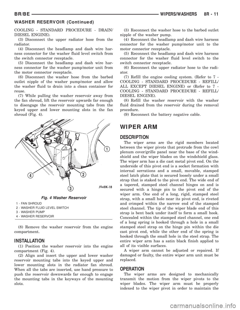
(7) While pulling the washer reservoir away from
the fan shroud, lift the reservoir upwards far enough
to disengage the reservoir mounting tabs from the
keyed upper and lower mounting slots in the fan
shroud (Fig. 4).
(8) Remove the washer reservoir from the engine
compartment.
INSTALLATION
(1) Position the washer reservoir into the engine
compartment (Fig. 4).
(2) Align and insert the upper and lower washer
reservoir mounting tabs into the keyed upper and
lower mounting slots in the radiator fan shroud.
When all the tabs are inserted, use hand pressure to
push the reservoir downwards far enough to engage
the mounting tabs in the keyways of the mounting
slots.(3) Reconnect the washer hose to the barbed outlet
nipple of the washer pump.
(4) Reconnect the headlamp and dash wire harness
connector for the washer pump/motor unit to the
motor connector receptacle.
(5) Reconnect the headlamp and dash wire harness
connector for the washer fluid level switch to the
switch connector receptacle.
(6) Reconnect the upper radiator hose to the radi-
ator.
(7) Refill the engine cooling system. (Refer to 7 -
COOLING - STANDARD PROCEDURE - REFILL/
ALL EXCEPT DIESEL ENGINE) or (Refer to 7 -
COOLING - STANDARD PROCEDURE - REFILL/
DIESEL ENGINE).
(8) Refill the washer reservoir with the washer
fluid drained from the reservoir during the removal
procedure.
(9) Reconnect the battery negative cable.
WIPER ARM
DESCRIPTION
The wiper arms are the rigid members located
between the wiper pivots that protrude from the cowl
plenum cover/grille panel near the base of the wind-
shield and the wiper blades on the windshield glass.
The wiper arm has a die cast metal pivot end. On the
underside of this pivot end is a socket formation with
internal serrations and a small, movable, stamped
steel latch plate that is secured loosely under a small
strap that is staked to the pivot end. The wide end of
a tapered, stamped steel channel hinges on and is
secured with a hinge pin to the pivot end of the
wiper arm. One end of a long, rigid, stamped steel
strap, with a small hole near its pivot end, is riveted
and crimped within the narrow end of the stamped
steel channel. The tip of the wiper blade end of this
strap is bent back under itself to form a small hook.
Concealed within the stamped steel channel, one end
of a long spring is hooked through a hole in a small
stamped steel strap on the hinge pin within the die
cast pivot end, while the other end of the spring is
hooked through the small hole in the steel strap. The
entire wiper arm has a satin black finish applied to
all of its visible surfaces.
A wiper arm cannot be adjusted or repaired. If
damaged or faulty, the entire wiper arm unit must be
replaced.
OPERATION
The wiper arms are designed to mechanically
transmit the motion from the wiper pivots to the
wiper blades. The wiper arm must be properly
indexed to the wiper pivot in order to maintain the
Fig. 4 Washer Reservoir
1 - FAN SHROUD
2 - WASHER FLUID LEVEL SWITCH
3 - WASHER PUMP
4 - WASHER RESERVOIR
BR/BEWIPERS/WASHERS 8R - 11
WASHER RESERVOIR (Continued)
Page 679 of 2255
Component Page
License Lamp......................... 8W-51
Low Note Horn....................... 8W-41
Manifold Absolute Pressure Sensor........ 8W-30
Outboard Clearance Lamps.............. 8W-50
Outboard Headlamps................... 8W-50
Outboard Identification Lamps........... 8W-50
Output Speed Sensor................... 8W-31
Overdrive Switch...................... 8W-31
Overhead Console..................... 8W-49
Oxygen Sensors....................... 8W-30
Oxygen Sensor Downstream Relay........ 8W-30
Park Brake Switch.................. 8W-40, 50
Park/Neutral Position Switch.......... 8W-30, 51
Park/Turn Signal Lamp................. 8W-52
Passenger Airbag On/Off Switch.......... 8W-43
Passenger Airbag...................... 8W-43
Passenger Cylinder Lock Switch.......... 8W-39
Passenger Door Ajar Switch.............. 8W-45
Passenger Door Lock Motor.............. 8W-61
Passenger Door Window/Lock Switch.... 8W-60, 61
Passenger Heated Seat Cushion.......... 8W-63
Passenger Heated Seat Switch........... 8W-63
Passenger Lumbar Motor................ 8W-63
Passenger Power Seat Front Vertical
Motor............................. 8W-63
Passenger Power Seat Horizontal Motor.... 8W-63
Passenger Power Seat Rear Vertical Motor . . 8W-63
Passenger Power Seat Switch............ 8W-63
Passenger Power Window Motor.......... 8W-60
Power Distribution Center............... 8W-10
Power Mirror Switch................... 8W-62Component Page
Power Mirror......................... 8W-62
Power Outlet......................... 8W-41
Powertrain Control Module.............. 8W-30
PTO Switch.......................... 8W-30
Quad High Beam Relay................. 8W-50
Radio Choke Relay..................... 8W-47
Radio............................... 8W-47
Rear Wheel Speed Sensor............ 8W-34, 35
Remote Radio Switch................... 8W-47
Splices.............................. 8W-70
Seat Belt Switch...................... 8W-40
Seat Heat Interface Module.............. 8W-63
Security Relay........................ 8W-39
Speakers............................ 8W-47
Speed Control Servo................... 8W-33
Speed Control Switches................. 8W-33
Tail/Stop/Turn Signal Lamp.............. 8W-51
Tailgate Lamps....................... 8W-51
Throttle Position Sensor................ 8W-30
Trailer Tow Connector.................. 8W-54
Trailer Tow Relay...................... 8W-54
Transmission Control Relay.............. 8W-31
Transmission Solenoid Assembly.......... 8W-31
Turn Signal/Hazard Switch.............. 8W-52
Underhood Lamp...................... 8W-44
Visor/Vanity Lamps.................... 8W-44
Washer Fluid Level Switch.............. 8W-40
Water In Fuel Sensor................... 8W-30
Wheel Speed Sensor.................... 8W-35
Windshield Washer Pump............... 8W-53
Wiper Motor Relay..................... 8W-53
8W - 02 - 2 8W-02 COMPONENT INDEXBR/BE
Page 730 of 2255
8W-15 GROUND DISTRIBUTION
Component Page
A/C Compressor Clutch.................8W-15-8, 10
A/C Heater Temperature Select.............8W-15-12
A/C-Heater Control.....................8W-15-14
Aftermarket Trailer Tow Connector............8W-15-6
Airbag Control Module....................8W-15-5
Ash Receiver Lamp.....................8W-15-14
Automatic Day/Night Mirror...............8W-15-13
Auxiliary Battery.......................8W-15-11
Battery.............................8W-15-11
Blend Door Actuator.....................8W-15-12
Blower Motor Relay......................8W-15-2
Brake Lamp Switch.....................8W-15-12
Brake Pressure Switch....................8W-15-3
Center High Mounted Stop Lamp No. 1........8W-15-17
Center High Mounted Stop Lamp No. 2........8W-15-17
Center Identification Lamp................8W-15-18
Central Timer Module.................8W-15-12, 13
Cigar Lighter.........................8W-15-14
Clockspring...........................8W-15-4
Combination Flasher....................8W-15-13
Controller Antilock Brake..................8W-15-5
Cummins Bus.........................8W-15-10
Cup Holder Lamp......................8W-15-14
Data Link Connector................8W-15-8, 10, 12
Daytime Running Lamp Module............8W-15-2, 3
Driver Cylinder Lock Switch...............8W-15-16
Driver Door Ajar Switch..................8W-15-16
Driver Door Window/Lock Switch..........8W-15-16, 17
Driver Heated Seat Cushion...............8W-15-15
Driver Heated Seat Switch................8W-15-13
Driver Power Seat Switch..............8W-15-15, 17
Electric Brake Provision..................8W-15-14
Engine Control Module....................8W-15-9
Engine Starter Motor Relay...............8W-15-8, 9
Fuel Heater..........................8W-15-10
Fuel Heater Relay.......................8W-15-2
Fuel Injection Pump.....................8W-15-9
Fuel Pump Module......................8W-15-7
Fuel Pump Relay.......................8W-15-2
Fuel Transfer Pump.....................8W-15-10
G100......................8W-15-2, 3, 4, 5, 7, 12
G101...............................8W-15-5
G102...............................8W-15-2
G105...............................8W-15-8
G107...............................8W-15-10
G113...............................8W-15-11
G114...............................8W-15-11
G115...............................8W-15-11
G116...............................8W-15-11
G117...............................8W-15-11
G118...............................8W-15-11
G120...............................8W-15-11
G200...........................8W-15-7, 12, 14
G201..........................8W-15-12, 13, 14
G300..........................8W-15-15, 16, 17
G301...............................8W-15-17
G302...............................8W-15-18
Glove Box Lamp And Switch...............8W-15-14
Headlamp Beam Select Switch..............8W-15-14
Headlamp Switch....................8W-15-13, 14
Heated Mirror Switch....................8W-15-13
High Note Horn........................8W-15-7
Ignition Switch........................8W-15-13
Instrument Cluster...................8W-15-12, 14
Component Page
Intake Air Heater Relay No. 1...............8W-15-9
Intake Air Heater Relay No. 2...............8W-15-9
Joint Connector No. 1...................8W-15-2, 5
Joint Connector No. 2....................8W-15-9
Joint Connector No. 5.................8W-15-13, 14
Joint Connector No. 6...................8W-15-4, 5
Joint Connector No. 8..................8W-15-5, 13
Junction Block...................8W-15-12, 13, 14
Left Back-Up Lamp......................8W-15-6
Left Front Door Speaker...................8W-15-4
Left Front Fender Lamp...................8W-15-6
Left License Lamp.......................8W-15-6
Left Outboard Clearance Lamp.............8W-15-18
Left Outboard Identification Lamp...........8W-15-18
Left Park/Turn Signal Lamp................8W-15-3
Left Power Mirror......................8W-15-16
Left Rear Fender Lamp...................8W-15-6
Left Remote Radio Switch..................8W-15-4
Left Tail/Stop/Turn Signal Lamp.............8W-15-6
Left Visor/Vanity Lamp...................8W-15-13
Low Note Horn.........................8W-15-7
Overdrive Switch.......................8W-15-12
Overhead Console......................8W-15-12
Oxygen Sensor 1/2 Left Bank Down...........8W-15-8
Oxygen Sensor 1/2 Pre-Catalyst..............8W-15-8
Oxygen Sensor 1/3 Post-Catalyst.............8W-15-8
Oxygen Sensor 2/2 Right Bank Down..........8W-15-8
Passenger Airbag On/Off Switch..............8W-15-5
Passenger Cylinder Lock Switch.............8W-15-16
Passenger Door Ajar Switch................8W-15-16
Passenger Door Window/Lock Switch..........8W-15-16
Passenger Heated Seat Cushion.............8W-15-15
Passenger Heated Seat Switch..............8W-15-13
Passenger Power Seat Switch..............8W-15-15
Power Distribution Center.................8W-15-2
Power Mirror Switch....................8W-15-16
Power Outlet.........................8W-15-14
Powertrain Control Module..............8W-15-8, 10
Quad High Beam Relay...................8W-15-2
Radio...............................8W-15-5
Radio Choke Relay......................8W-15-4
Right Back-Up Lamp.....................8W-15-6
Right Front Door Speaker..................8W-15-4
Right Front Fender Lamp..................8W-15-6
Right License Lamp......................8W-15-6
Right Outboard Clearance Lamp............8W-15-18
Right Outboard Identification Lamp..........8W-15-18
Right Park/Turn Signal Lamp...............8W-15-7
Right Power Mirror.....................8W-15-16
Right Rear Fender Lamp..................8W-15-6
Right Remote Radio Switch.................8W-15-4
Right Tail/Stop/Turn Signal Lamp............8W-15-6
Right Visor/Vanity Lamp..................8W-15-13
Seat Belt Switch.....................8W-15-15, 17
Seat Heat Interface Module................8W-15-15
Security Relay.........................8W-15-2
Speed Control Servo.....................8W-15-3
Tailgate Lamp.........................8W-15-6
Trailer Tow Connector....................8W-15-6
Trailer Tow Relay.......................8W-15-2
Underhood Lamp.......................8W-15-3
Washer Fluid Level Switch.................8W-15-3
Windshield Washer Pump..................8W-15-7
Wiper Motor...........................8W-15-7
BR/BE8W-15 GROUND DISTRIBUTION 8W - 15 - 1
Page 938 of 2255

Component Page
Left Rear Fender Lamp
(Dual Rear Wheels)................ 8W-80-59
Left Rear Speaker (Premium 2 Door).... 8W-80-59
Left Rear Speaker (Premium 4 Door).... 8W-80-60
Left Rear Speaker (Standard 2 Door).... 8W-80-60
Left Rear Speaker (Standard 4 Door).... 8W-80-60
Left Remote Radio Switch............. 8W-80-60
Left Speed Control Switch............ 8W-80-60
Left Tail/Stop/Turn Signal Lamp........ 8W-80-61
Left Tweeter (Premium).............. 8W-80-61
Left Visor/Vanity Lamp............... 8W-80-61
Low Note Horn..................... 8W-80-61
Manifold Absolute Pressure Sensor
(3.9L/5.2L/5.9L)................... 8W-80-61
Manifold Absolute Pressure Sensor
(8.0L).......................... 8W-80-62
Manifold Air Pressure Sensor (Diesel).... 8W-80-62
Multi-Function Switch............... 8W-80-62
Output Speed Sensor................ 8W-80-63
Overdrive Switch................... 8W-80-63
Overhead Console (Base).............. 8W-80-63
Overhead Console (Highline)........... 8W-80-63
Oxygen Sensor 1/1 Left Bank Up
(5.9L HD/8.0L)................... 8W-80-63
Oxygen Sensor 1/1 Left Bank Up
(California)...................... 8W-80-64
Oxygen Sensor 1/1 Upstream
(A/T Except 8.0L)................. 8W-80-64
Oxygen Sensor 1/1 Upstream
(M/T Except 8.0L)................. 8W-80-64
Oxygen Sensor 1/2 Downstream
(3.9L/5.2L)....................... 8W-80-64
Oxygen Sensor 1/2 Left Bank Down
(California)...................... 8W-80-64
Oxygen Sensor 1/2 Pre-Catalyst (8.0L) . . . 8W-80-65
Oxygen Sensor 1/3 Post Catalyst (8.0L) . . 8W-80-65
Oxygen Sensor 2/1 Right Bank Up (5.9l HD)
(5.2L/5.9L/8.0L California).......... 8W-80-65
Oxygen Sensor 2/2 Right Bank Down
(California)...................... 8W-80-65
Park/Neutral Position Switch (A/T)...... 8W-80-65
Passenger Airbag................... 8W-80-66
Passenger Airbag On/Off Switch C1..... 8W-80-66
Passenger Airbag On/Off Switch C2..... 8W-80-66
Passenger Cylinder Lock Switch........ 8W-80-66
Passenger Door Ajar Switch........... 8W-80-66
Passenger Door Lock Motor........... 8W-80-66
Passenger Door Window/Lock Switch.... 8W-80-67
Passenger Heated Seat Cushion........ 8W-80-67
Passenger Heated Seat Switch......... 8W-80-67
Passenger Lumbar Motor............. 8W-80-67
Passenger Power Seat Front Vertical Motor
(Club Cab)....................... 8W-80-68
Passenger Power Seat Horizontal Motor
(Club Cab)....................... 8W-80-68Component Page
Passenger Power Seat Rear Vertical Motor
(Club Cab)....................... 8W-80-68
Passenger Power Seat Switch (Club Cab) . 8W-80-68
Passenger Power Window Motor........ 8W-80-68
Power Mirror Switch................. 8W-80-69
Power Outlet....................... 8W-80-69
Powertrain Control Module C1 (Diesel) . . . 8W-80-69
Powertrain Control Module C1 (Gas).... 8W-80-70
Powertrain Control Module C2 (Diesel) . . . 8W-80-71
Powertrain Control Module C2 (Gas).... 8W-80-71
Powertrain Control Module C3 (Diesel) . . . 8W-80-72
Powertrain Control Module C3 (Gas).... 8W-80-73
Radio C1.......................... 8W-80-74
Radio C2.......................... 8W-80-74
Radio C3.......................... 8W-80-74
Radio Choke Relay.................. 8W-80-74
Rear Wheel Speed Sensor (ABS)........ 8W-80-74
Right Back-Up Lamp................ 8W-80-75
Right Fog Lamp.................... 8W-80-75
Right Front Door Speaker (Premium).... 8W-80-75
Right Front Door Speaker (Standard).... 8W-80-75
Right Front Fender Lamp
(Dual Rear Wheels)................ 8W-80-75
Right Front Wheel Speed Sensor (ABS) . . 8W-80-76
Right Headlamp.................... 8W-80-76
Right License Lamp................. 8W-80-76
Right Outboard Clearance Lamp....... 8W-80-76
Right Outboard Headlamp............ 8W-80-76
Right Outboard Identification Lamp..... 8W-80-77
Right Park/Turn Signal Lamp.......... 8W-80-77
Right Power Mirror.................. 8W-80-77
Right Rear Fender Lamp
(Dual Rear Wheels)................ 8W-80-77
Right Rear Speaker (2 Door Premium) . . . 8W-80-77
Right Rear Speaker (4 Door Premium) . . . 8W-80-78
Right Rear Speaker (Standard 2 Door) . . . 8W-80-78
Right Rear Speaker (Standard 4 Door) . . . 8W-80-78
Right Remote Radio Switch........... 8W-80-78
Right Speed Control Switch........... 8W-80-78
Right Tail/Stop/Turn Signal Lamp...... 8W-80-78
Right Tweeter (Premium)............. 8W-80-79
Right Visor/Vanity Lamp.............. 8W-80-79
Seat Belt Switch (Club Cab)........... 8W-80-79
Seat Belt Switch (Standard Cab)....... 8W-80-79
Seat Heat Interface Module........... 8W-80-79
Speed Control Servo................. 8W-80-80
Tailgate Lamp (Dual Rear Wheels)...... 8W-80-80
Throttle Position Sensor (Gas)......... 8W-80-80
Trailer Tow Connector................ 8W-80-80
Transmission Solenoid Assembly........ 8W-80-80
Underhood Lamp................... 8W-80-81
Washer Fluid Level Switch............ 8W-80-81
Water In Fuel Sensor (Diesel).......... 8W-80-81
Wiper Motor....................... 8W-80-81
BR/BE8W-80 CONNECTOR PIN-OUTS 8W - 80 - 3
Page 1016 of 2255
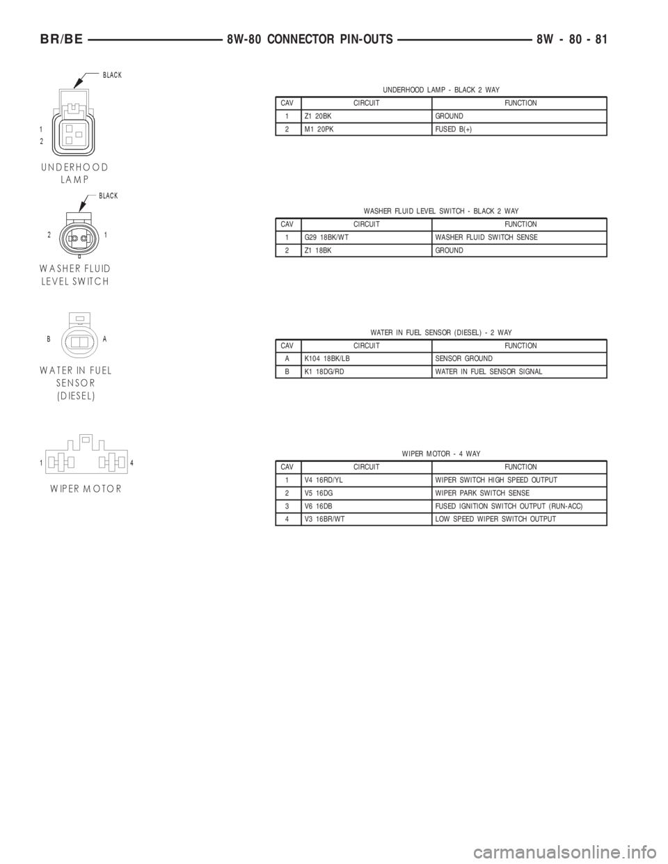
UNDERHOOD LAMP - BLACK 2 WAY
CAV CIRCUIT FUNCTION
1 Z1 20BK GROUND
2 M1 20PK FUSED B(+)
WASHER FLUID LEVEL SWITCH - BLACK 2 WAY
CAV CIRCUIT FUNCTION
1 G29 18BK/WT WASHER FLUID SWITCH SENSE
2 Z1 18BK GROUND
WATER IN FUEL SENSOR (DIESEL)-2WAY
CAV CIRCUIT FUNCTION
A K104 18BK/LB SENSOR GROUND
B K1 18DG/RD WATER IN FUEL SENSOR SIGNAL
WIPER MOTOR-4WAY
CAV CIRCUIT FUNCTION
1 V4 16RD/YL WIPER SWITCH HIGH SPEED OUTPUT
2 V5 16DG WIPER PARK SWITCH SENSE
3 V6 16DB FUSED IGNITION SWITCH OUTPUT (RUN-ACC)
4 V3 16BR/WT LOW SPEED WIPER SWITCH OUTPUT
BR/BE8W-80 CONNECTOR PIN-OUTS 8W - 80 - 81
Page 1025 of 2255
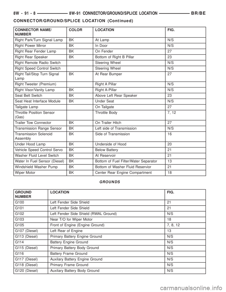
CONNECTOR NAME/
NUMBERCOLOR LOCATION FIG.
Right Park/Turn Signal Lamp BK At Lamp N/S
Right Power Mirror BK In Door N/S
Right Rear Fender Lamp BK On Fender 27
Right Rear Speaker BK Bottom of Right B Pillar 23
Right Remote Radio Switch Steering Wheel N/S
Right Speed Control Switch Steering Wheel N/S
Right Tail/Stop Turn Signal
LampBK At Rear Bumper 27
Right Tweeter (Premium) Right A Pillar N/S
Right Visor/Vanity Lamp BK Right A-Pillar N/S
Seat Belt Switch BK Above Left Rear Speaker 23
Seat Heat Interface Module BK Under Seat N/S
Tailgate Lamp On Tailgate 27
Throttle Position Sensor
(Gas)Throttle Body 7, 12
Trailer Tow Connector BK On Trailer Hitch 27
Transmission Range Sensor BK Left side of Transmission N/S
Transmission Solenoid
AssemblyBK Side of Transmission 16
Under Hood Lamp BK Underside of Hood 20
Vehicle Speed Control Servo BK Below Battery 21
Washer Fluid Level Switch BK At Reservoir 21
Water In Fuel Sensor (Diesel) BK Bottom of Fuel Filter/Water Separator 13
Windshield Washer Pump BK Bottom of Washer Fluid Reservior 21
Wiper Motor BK Center Rear Engine Compartment 18
GROUNDS
GROUND
NUMBERLOCATION FIG.
G100 Left Fender Side Shield 21
G101 Left Fender Side Shield 21
G102 Left Fender Side Shield (RWAL Ground) N/S
G103 Near T/O for Wiper Motor 18
G105 Front of Engine (Engine Ground) 7, 8, 12
G107 (Diesel) Left Rear of Engine 13
G113 (Diesel) Primary Battery Engine Ground N/S
G114 Battery Engine Ground N/S
G115 (Diesel) Primary Battery Body Ground N/S
G116 Battery Frame Ground N/S
G117 (Diesel) Auxilary Battery Engine Ground N/S
G118 (Diesel) Primary Frame Ground N/S
G120 (Diesel) Auxilary Battery Body Ground N/S
8W - 91 - 8 8W-91 CONNECTOR/GROUND/SPLICE LOCATIONBR/BE
CONNECTOR/GROUND/SPLICE LOCATION (Continued)
Page 1142 of 2255
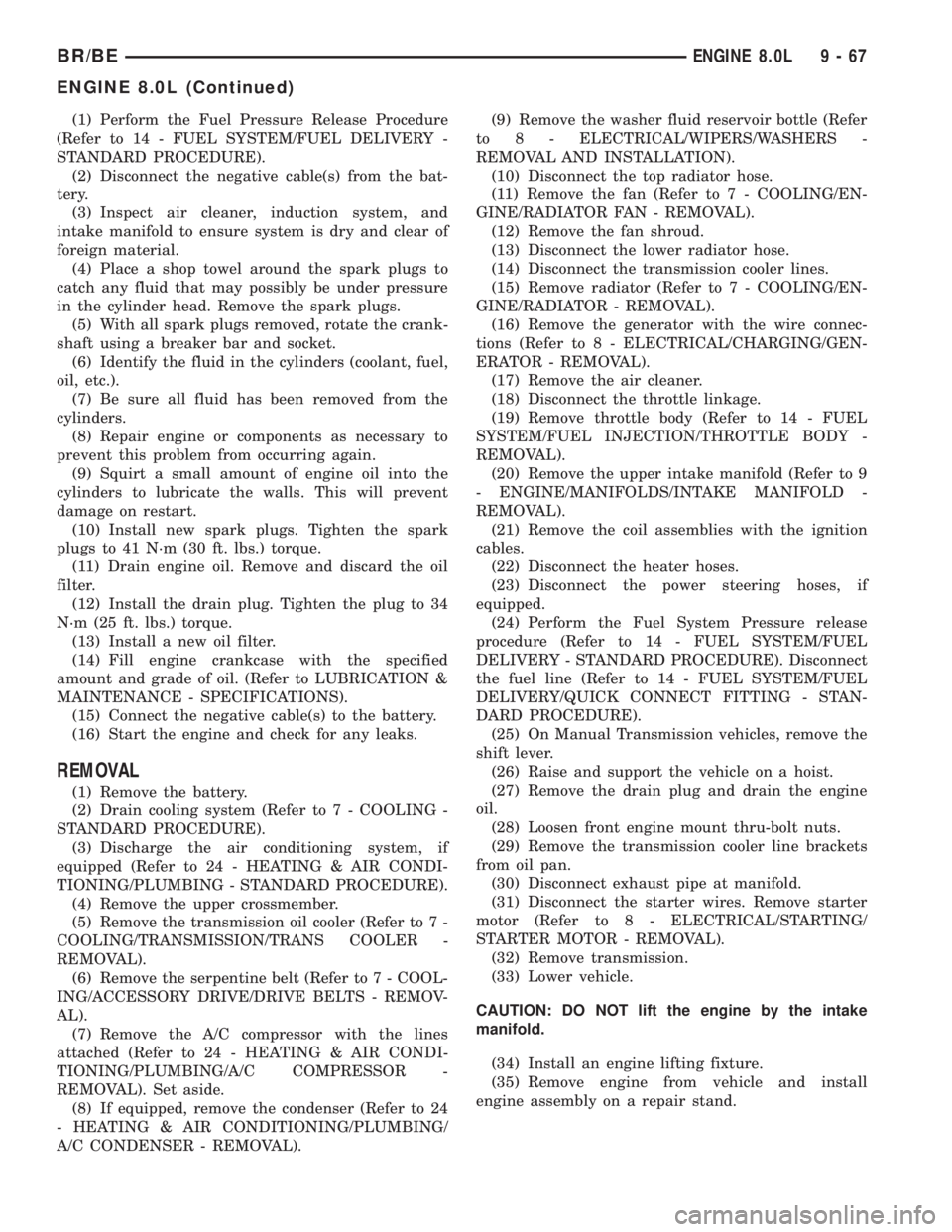
(1) Perform the Fuel Pressure Release Procedure
(Refer to 14 - FUEL SYSTEM/FUEL DELIVERY -
STANDARD PROCEDURE).
(2) Disconnect the negative cable(s) from the bat-
tery.
(3) Inspect air cleaner, induction system, and
intake manifold to ensure system is dry and clear of
foreign material.
(4) Place a shop towel around the spark plugs to
catch any fluid that may possibly be under pressure
in the cylinder head. Remove the spark plugs.
(5) With all spark plugs removed, rotate the crank-
shaft using a breaker bar and socket.
(6) Identify the fluid in the cylinders (coolant, fuel,
oil, etc.).
(7) Be sure all fluid has been removed from the
cylinders.
(8) Repair engine or components as necessary to
prevent this problem from occurring again.
(9) Squirt a small amount of engine oil into the
cylinders to lubricate the walls. This will prevent
damage on restart.
(10) Install new spark plugs. Tighten the spark
plugs to 41 N´m (30 ft. lbs.) torque.
(11) Drain engine oil. Remove and discard the oil
filter.
(12) Install the drain plug. Tighten the plug to 34
N´m (25 ft. lbs.) torque.
(13) Install a new oil filter.
(14) Fill engine crankcase with the specified
amount and grade of oil. (Refer to LUBRICATION &
MAINTENANCE - SPECIFICATIONS).
(15) Connect the negative cable(s) to the battery.
(16) Start the engine and check for any leaks.
REMOVAL
(1) Remove the battery.
(2) Drain cooling system (Refer to 7 - COOLING -
STANDARD PROCEDURE).
(3) Discharge the air conditioning system, if
equipped (Refer to 24 - HEATING & AIR CONDI-
TIONING/PLUMBING - STANDARD PROCEDURE).
(4) Remove the upper crossmember.
(5) Remove the transmission oil cooler (Refer to 7 -
COOLING/TRANSMISSION/TRANS COOLER -
REMOVAL).
(6) Remove the serpentine belt (Refer to 7 - COOL-
ING/ACCESSORY DRIVE/DRIVE BELTS - REMOV-
AL).
(7) Remove the A/C compressor with the lines
attached (Refer to 24 - HEATING & AIR CONDI-
TIONING/PLUMBING/A/C COMPRESSOR -
REMOVAL). Set aside.
(8) If equipped, remove the condenser (Refer to 24
- HEATING & AIR CONDITIONING/PLUMBING/
A/C CONDENSER - REMOVAL).(9) Remove the washer fluid reservoir bottle (Refer
to 8 - ELECTRICAL/WIPERS/WASHERS -
REMOVAL AND INSTALLATION).
(10) Disconnect the top radiator hose.
(11) Remove the fan (Refer to 7 - COOLING/EN-
GINE/RADIATOR FAN - REMOVAL).
(12) Remove the fan shroud.
(13) Disconnect the lower radiator hose.
(14) Disconnect the transmission cooler lines.
(15) Remove radiator (Refer to 7 - COOLING/EN-
GINE/RADIATOR - REMOVAL).
(16) Remove the generator with the wire connec-
tions (Refer to 8 - ELECTRICAL/CHARGING/GEN-
ERATOR - REMOVAL).
(17) Remove the air cleaner.
(18) Disconnect the throttle linkage.
(19) Remove throttle body (Refer to 14 - FUEL
SYSTEM/FUEL INJECTION/THROTTLE BODY -
REMOVAL).
(20) Remove the upper intake manifold (Refer to 9
- ENGINE/MANIFOLDS/INTAKE MANIFOLD -
REMOVAL).
(21) Remove the coil assemblies with the ignition
cables.
(22) Disconnect the heater hoses.
(23) Disconnect the power steering hoses, if
equipped.
(24) Perform the Fuel System Pressure release
procedure (Refer to 14 - FUEL SYSTEM/FUEL
DELIVERY - STANDARD PROCEDURE). Disconnect
the fuel line (Refer to 14 - FUEL SYSTEM/FUEL
DELIVERY/QUICK CONNECT FITTING - STAN-
DARD PROCEDURE).
(25) On Manual Transmission vehicles, remove the
shift lever.
(26) Raise and support the vehicle on a hoist.
(27) Remove the drain plug and drain the engine
oil.
(28) Loosen front engine mount thru-bolt nuts.
(29) Remove the transmission cooler line brackets
from oil pan.
(30) Disconnect exhaust pipe at manifold.
(31) Disconnect the starter wires. Remove starter
motor (Refer to 8 - ELECTRICAL/STARTING/
STARTER MOTOR - REMOVAL).
(32) Remove transmission.
(33) Lower vehicle.
CAUTION: DO NOT lift the engine by the intake
manifold.
(34) Install an engine lifting fixture.
(35) Remove engine from vehicle and install
engine assembly on a repair stand.
BR/BEENGINE 8.0L 9 - 67
ENGINE 8.0L (Continued)
Page 1143 of 2255
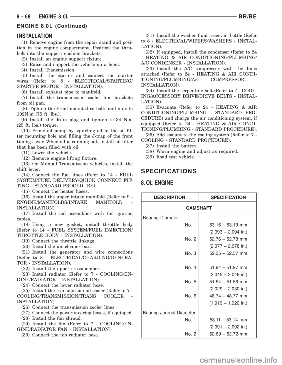
INSTALLATION
(1) Remove engine from the repair stand and posi-
tion in the engine compartment. Position the thru-
bolt into the support cushion brackets.
(2) Install an engine support fixture.
(3) Raise and support the vehicle on a hoist.
(4) Install Transmission.
(5) Install the starter and connect the starter
wires (Refer to 8 - ELECTRICAL/STARTING/
STARTER MOTOR - INSTALLATION).
(6) Install exhaust pipe to manifold.
(7) Install the transmission cooler line brackets
from oil pan.
(8) Tighten the Front mount thru-bolts and nuts to
102N´m (75 ft. lbs.).
(9) Install the drain plug and tighten to 34 N´m
(25 ft. lbs.) torque.
(10) Prime oil pump by squirting oil in the oil fil-
ter mounting hole and filling the J-trap of the front
timing cover. When oil is running out, install oil filter
that has been filled with oil.
(11) Lower the vehicle.
(12) Remove engine lifting fixture.
(13) On Manual Transmission vehicles, install the
shift lever.
(14) Connect the fuel lines (Refer to 14 - FUEL
SYSTEM/FUEL DELIVERY/QUICK CONNECT FIT-
TING - STANDARD PROCEDURE).
(15) Connect the heater hoses.
(16) Install the upper intake manifold (Refer to 9 -
ENGINE/MANIFOLDS/INTAKE MANIFOLD -
INSTALLATION).
(17) Install the coil assemblies with the ignition
cables.
(18) Using a new gasket, install throttle body
(Refer to 14 - FUEL SYSTEM/FUEL INJECTION/
THROTTLE BODY - INSTALLATION).
(19) Connect the throttle linkage.
(20) Install the air cleaner box.
(21) Install the generator and wire connections
(Refer to 8 - ELECTRICAL/CHARGING/GENERA-
TOR - INSTALLATION).
(22) Install the upper crossmember.
(23) Install radiator (Refer to 7 - COOLING/EN-
GINE/RADIATOR - INSTALLATION).
(24) Connect the lower radiator hose.
(25) Install the transmission oil cooler (Refer to 7 -
COOLING/TRANSMISSION/TRANS COOLER -
INSTALLATION).
(26) Connect the transmission cooler lines.
(27) Connect the power steering hoses, if equipped.
(28) Install the fan shroud.
(29) Install the fan (Refer to 7 - COOLING/EN-
GINE/RADIATOR FAN - INSTALLATION).
(30) Connect the top radiator hose.(31) Install the washer fluid reservoir bottle (Refer
to 8 - ELECTRICAL/WIPERS/WASHERS - INSTAL-
LATION).
(32) If equipped, install the condenser (Refer to 24
- HEATING & AIR CONDITIONING/PLUMBING/
A/C CONDENSER - INSTALLATION).
(33) Install the A/C compressor with the lines
attached (Refer to 24 - HEATING & AIR CONDI-
TIONING/PLUMBING/A/C COMPRESSOR -
INSTALLATION).
(34) Install the serpentine belt (Refer to 7 - COOL-
ING/ACCESSORY DRIVE/DRIVE BELTS - INSTAL-
LATION).
(35) Evacuate (Refer to 24 - HEATING & AIR
CONDITIONING/PLUMBING - STANDARD PRO-
CEDURE) and charge the air conditioning system, if
equipped (Refer to 24 - HEATING & AIR CONDI-
TIONING/PLUMBING - STANDARD PROCEDURE).
(36) Add coolant to the cooling system (Refer to 7 -
COOLING - STANDARD PROCEDURE).
(37) Install the battery.
(38) Warm engine and adjust as required.
(39) Road test vehicle.
SPECIFICATIONS
8.OL ENGINE
DESCRIPTION SPECIFICATION
CAMSHAFT
Bearing Diameter
No. 1 53.16 ± 53.19 mm
(2.093 ± 2.094 in.)
No. 2 52.76 ± 52.78 mm
(2.077 ± 2.078 in.)
No. 3 52.35 ± 52.37 mm
No. 4 51.94 ± 51.97 mm
(2.045 ± 2.046 in.)
No. 5 51.54 ± 51.56 mm
(2.029 ± 2.030 in.)
No. 6 48.74 ± 48.77 mm
(1.919 ± 1.920 in.)
Bearing Journal Diameter
No. 1 53.11 ± 53.14 mm
(2.091 ± 2.092 in.)
No. 2 52.69 ± 52.72 mm
9 - 68 ENGINE 8.0LBR/BE
ENGINE 8.0L (Continued)
Page 2219 of 2255
AIR LEAK VACUUM TEST - DIAGNOSIS
AND TESTING, FUEL SYSTEM...........14-57
AIR PUMP FILTER - INSTALLATION......25-30
AIR PUMP FILTER - REMOVAL..........25-30
AIR TESTING TRANSMISSION CLUTCH
AND BAND OPERATION - DIAGNOSIS
AND TESTING................21-100,21-272
AIR TO OIL COOLER - INSTALLATION.....7-87
AIR TO OIL COOLER - REMOVAL.........7-86
AIRBAG - ASSEMBLY, DRIVER..........8O-16
AIRBAG - DESCRIPTION, DRIVER........8O-14
AIRBAG - DESCRIPTION, PASSENGER....8O-21
AIRBAG - DISASSEMBLY, DRIVER.......8O-15
AIRBAG - INSTALLATION, DRIVER.......8O-17
AIRBAG - INSTALLATION, PASSENGER . . . 8O-23
AIRBAG - OPERATION, DRIVER.........8O-14
AIRBAG - OPERATION, PASSENGER......8O-21
AIRBAG - REMOVAL, DRIVER...........8O-14
AIRBAG - REMOVAL, PASSENGER.......8O-21
AIRBAG CONTROL MODULE -
DESCRIPTION........................8O-6
AIRBAG CONTROL MODULE -
INSTALLATION.......................8O-8
AIRBAG CONTROL MODULE -
OPERATION..........................8O-6
AIRBAG CONTROL MODULE - REMOVAL . . . 8O-7
AIRBAG DEPLOYMENT - STANDARD
PROCEDURE, SERVICE AFTER AN........8O-4
AIRBAG INDICATOR - DESCRIPTION.......8J-15
AIRBAG INDICATOR - OPERATION.......8J-15
AIRBAG ON/OFF SWITCH -
DESCRIPTION, PASSENGER............8O-23
AIRBAG ON/OFF SWITCH -
INSTALLATION, PASSENGER...........8O-25
AIRBAG ON/OFF SWITCH - OPERATION,
PASSENGER........................8O-24
AIRBAG ON/OFF SWITCH - REMOVAL,
PASSENGER........................8O-24
AIRBAG SYSTEM - DIAGNOSIS AND
TESTING............................8O-4
AIRBAG SYSTEM - SPECIAL TOOLS.......8O-6
AIRBAGS - STANDARD PROCEDURE,
HANDLING NON-DEPLOYED.............8O-4
AIRFLOW - DESCRIPTION, HVAC
SYSTEM............................24-30
AJAR SWITCH - DESCRIPTION, DOOR....8L-34
AJAR SWITCH - DIAGNOSIS AND
TESTING, DOOR.....................8L-34
AJAR SWITCH - INSTALLATION, DOOR . . . 8L-35
AJAR SWITCH - REMOVAL, DOOR.......8L-35
ALIGNMENT - DESCRIPTION, WHEEL.......2-1
ALIGNMENT - OPERATION, WHEEL........2-2
ALIGNMENT I.F.S. - STANDARD
PROCEDURES.........................2-3
ALIGNMENT LINK/COIL SUSPENSION -
STANDARD PROCEDURE.................2-5
ALIGNMENT, SPECIAL TOOLS -
HEADLAMP..........................8L-4
ALIGNMENT, SPECIFICATIONS............2-6
ALUMINUM THREAD REPAIR -
STANDARD PROCEDURE........21-114,21-286
AMBIENT TEMP SENSOR - DESCRIPTION . 8M-12
AMBIENT TEMP SENSOR -
INSTALLATION......................8M-13
AMBIENT TEMP SENSOR - OPERATION . . 8M-12
AMBIENT TEMP SENSOR - REMOVAL
....8M-12
AMBIENT TEMPERATURE SENSOR -
DIAGNOSIS AND TESTING
.............8M-12
AMPERAGE TEST - DIAGNOSIS AND
TESTING, FUEL PUMP
.................14-10
ANTENNA - DIAGNOSIS AND TESTING
.....8A-5
ANTENNA BODY & CABLE -
DESCRIPTION
........................8A-4
ANTENNA BODY & CABLE -
INSTALLATION
.......................8A-6
ANTENNA BODY & CABLE - OPERATION
. . . 8A-4
ANTENNA BODY & CABLE - REMOVAL
.....8A-6
ANTENNA CABLE - INSTALLATION,
INSTRUMENT PANEL
..................8A-9
ANTENNA CABLE - REMOVAL,
INSTRUMENT PANEL
..................8A-9
ANTILOCK BRAKE - DESCRIPTION,
CONTROLLER
.......................8E-11
ANTILOCK BRAKE - INSTALLATION,
CONTROLLER
.......................8E-12
ANTILOCK BRAKE - OPERATION,
CONTROLLER
.......................8E-11ANTILOCK BRAKE - REMOVAL,
CONTROLLER.......................8E-11
ANTILOCK BRAKES - DIAGNOSIS AND
TESTING............................5-36
A-PILLAR GRAB HANDLE -
INSTALLATION......................23-119
A-PILLAR GRAB HANDLE - REMOVAL . . . 23-119
A-PILLAR TRIM - INSTALLATION.......23-119
A-PILLAR TRIM - REMOVAL...........23-119
A-PILLAR TWEETER SPEAKER -
INSTALLATION.......................8A-19
A-PILLAR TWEETER SPEAKER -
REMOVAL..........................8A-18
APPLICATION TABLE, SPECIFICATIONS -
A/C ................................24-7
APPLIQUE - INSTALLATION........23-63,23-68
APPLIQUE - REMOVAL...........23-63,23-68
ARM / ADJUSTER ASSEMBLY -
INSTALLATION, ROCKER................9-26
ARM / ADJUSTER ASSEMBLY -
REMOVAL, ROCKER...................9-26
ARM / ADJUSTER ASSY - CLEANING,
ROCKER............................9-146
ARM / ADJUSTER ASSY - DESCRIPTION,
ROCKER............................9-145
ARM / ADJUSTER ASSY - INSPECTION,
ROCKER............................9-146
ARM / ADJUSTER ASSY -
INSTALLATION, ROCKER...........9-148,9-84
ARM / ADJUSTER ASSY - REMOVAL,
ROCKER.......................9-145,9-84
ARM - DESCRIPTION, WIPER............8R-11
ARM - INSTALLATION, LOWER
CONTROL.......................2-10,2-20
ARM - INSTALLATION, UPPER
CONTROL.......................2-13,2-19
ARM - INSTALLATION, WIPER..........8R-12
ARM - OPERATION, WIPER............8R-11
ARM - REMOVAL, LOWER CONTROL . . 2-10,2-20
ARM - REMOVAL, UPPER CONTROL . . 2-13,2-19
ARM - REMOVAL, WIPER..............8R-12
ARMREST/CONSOLE - INSTALLATION,
CENTER SEAT......................23-132
ARMREST/CONSOLE - REMOVAL,
CENTER SEAT......................23-132
ARMREST/LATCH COVER -
INSTALLATION, CENTER SEAT.........23-132
ARMREST/LATCH COVER - REMOVAL,
CENTER SEAT......................23-132
ASD AND FUEL PUMP RELAYS -
DIAGNOSIS AND TESTING...............8I-4
ASD SENSE - PCM INPUT - OPERATION....8I-4
ASH RECEIVER - INSTALLATION........23-107
ASH RECEIVER - REMOVAL...........23-107
ASSEMBLY - INSTALLATION,
INSTRUMENT PANEL.................23-117
ASSEMBLY - INSTALLATION, ROCKER
ARM / ADJUSTER.....................9-26
ASSEMBLY - OVERHEAD CONSOLE
ASSEMBLY..........................8M-8
ASSEMBLY - REMOVAL, INSTRUMENT
PANEL............................23-115
ASSEMBLY - REMOVAL, ROCKER ARM /
ADJUSTER...........................9-26
ASSEMBLY, ASSEMBLY - OVERHEAD
CONSOLE...........................8M-8
ASSEMBLY, AXLE VACUUM MOTOR.......3-34
ASSEMBLY, DIAGNOSIS AND
TESTING....................21-122,21-294
ASSEMBLY, DIFFERENTIAL . 3-126,3-38,3-66,3-97
ASSEMBLY, DIFFERENTIAL - POWR-LOK . . . 3-99
ASSEMBLY, DIFFERENTIAL -
TRAC-LOK......................3-129,3-70
ASSEMBLY, DOUBLE CARDAN
UNIVERSAL JOINTS
...................3-11
ASSEMBLY, DRIVER AIRBAG
...........8O-16
ASSEMBLY, FLYWHEEL
.................6-14
ASSEMBLY, FRONT CLUTCH
.....21-162,21-333
ASSEMBLY, FRONT SERVO
......21-164,21-335
ASSEMBLY, GLOVE BOX
..............23-111
ASSEMBLY, HVAC HOUSING
............24-36
ASSEMBLY, INSTRUMENT CLUSTER
......8J-12
ASSEMBLY, MANUAL - NV4500
.........21-21
ASSEMBLY, MANUAL - NV5600
.........21-64
ASSEMBLY, OIL PUMP
.................9-49
ASSEMBLY, OIL PUMP
.........21-169,21-340
ASSEMBLY, OVERDRIVE UNIT
....21-180,21-354ASSEMBLY, OVERRUNNING CLUTCH
CAM/OVERDRIVE PISTON
RETAINER...................21-193,21-364
ASSEMBLY, PLANETARY GEARTRAIN/
OUTPUT SHAFT...............21-199,21-371
ASSEMBLY, REAR CLUTCH......21-205,21-377
ASSEMBLY, REAR SERVO.......21-207,21-379
ASSEMBLY, SINGLE CARDAN
UNIVERSAL JOINTS....................3-9
ASSEMBLY, TRANSFER CASE - NV241HD . 21-480
ASSEMBLY, TRANSFER CASE - NV241LD . 21-445
ASSEMBLY, VALVE BODY.......21-248,21-420
ASSIST HANDLE - INSTALLATION.......23-124
ASSIST HANDLE - REMOVAL..........23-124
ASSY - CLEANING, ROCKER ARM /
ADJUSTER..........................9-146
ASSY - DESCRIPTION, ROCKER ARM /
ADJUSTER..........................9-145
ASSY - INSPECTION, ROCKER ARM /
ADJUSTER..........................9-146
ASSY - INSTALLATION, ROCKER ARM /
ADJUSTER......................9-148,9-84
ASSY - REMOVAL, ROCKER ARM /
ADJUSTER......................9-145,9-84
AUDIO - DESCRIPTION.................8A-1
AUDIO - DIAGNOSIS AND TESTING.......8A-2
AUDIO - OPERATION...................8A-2
AUDIO SYSTEMS, SPECIAL TOOLS.......8A-4
AUTO. TRANS. - INSTALLATION, DIESEL
WITH..........................8P-12,8P-6
AUTO. TRANS. - REMOVAL, DIESEL
WITH...........................8P-5,8P-9
AUTOMATIC DAY / NIGHT MIRROR -
DESCRIPTION.......................8N-11
AUTOMATIC DAY / NIGHT MIRROR -
INSTALLATION......................8N-13
AUTOMATIC DAY / NIGHT MIRROR -
OPERATION.........................8N-12
AUTOMATIC DAY / NIGHT MIRROR -
REMOVAL..........................8N-13
AUTOMATIC DAY/NIGHT MIRROR -
DIAGNOSIS AND TESTING.............8N-12
AUTOMATIC TRANSMISSION - 46RE -
DESCRIPTION.......................21-89
AUTOMATIC TRANSMISSION - 46RE -
OPERATION.........................21-91
AUTOMATIC TRANSMISSION - 47RE -
DESCRIPTION......................21-261
AUTOMATIC TRANSMISSION - 47RE -
OPERATION........................21-263
AUTOMATIC TRANSMISSION -
DIAGNOSIS AND TESTING.......21-268,21-96
AUTOMATIC TRANSMISSION FLUID -
DESCRIPTION.........................0-6
AUTOMATIC TRANSMISSION FLUID -
OPERATION...........................0-6
AXLE - 248FBI - ADJUSTMENTS, FRONT . . . 3-19
AXLE - 248FBI - DESCRIPTION, FRONT....3-14
AXLE - 248FBI - INSTALLATION, FRONT....3-18
AXLE - 248FBI - OPERATION, FRONT......3-14
AXLE - 248FBI - REMOVAL, FRONT.......3-18
AXLE - 248RBI - ADJUSTMENTS, REAR....3-51
AXLE - 248RBI - DESCRIPTION, REAR.....3-46
AXLE - 248RBI - INSTALLATION, REAR....3-51
AXLE - 248RBI - OPERATION, REAR.......3-46
AXLE - 248RBI - REMOVAL, REAR........3-51
AXLE - 267RBI - ADJUSTMENTS, REAR....3-83
AXLE - 267RBI - DESCRIPTION, REAR.....3-78
AXLE - 267RBI - INSTALLATION, REAR....3-82
AXLE - 267RBI - OPERATION, REAR.......3-78
AXLE - 267RBI - REMOVAL, REAR........3-82
AXLE - 286RBI - ADJUSTMENTS, REAR . . . 3-112
AXLE - 286RBI - DESCRIPTION, REAR....3-107
AXLE - 286RBI - INSTALLATION, REAR . . . 3-112
AXLE - 286RBI - OPERATION, REAR......3-108
AXLE - 286RBI - REMOVAL, REAR.......3-112
AXLE - DIAGNOSIS AND
TESTING...............3-108,3-15,3-47,3-80
AXLE - INSTALLATION, DANA 44.....2-20,2-21
AXLE - INSTALLATION, DANA 60.....2-20,2-22
AXLE - INSTALLATION, INTERMEDIATE....3-30
AXLE - REMOVAL, DANA 44.............2-21
AXLE - REMOVAL, DANA 60.............2-21
AXLE, 248FBI - FRONT
.................3-27
AXLE, 248RBI - REAR
..................3-59
AXLE, 267RBI - REAR
..................3-91
AXLE, 286 RBI - REAR
................3-120
AXLE, 286RBI - REAR
.................3-120
2 INDEXBR/BE
Description Group-Page Description Group-Page Description Group-Page
Page 2223 of 2255
CENTRAL TIMER MODULE - REMOVAL....8E-5
CERTIFICATION LABEL - DESCRIPTION,
VEHICLE SAFETY...................Intro.-1
CHAIN COVER(S) - INSTALLATION,
TIMING BELT....................9-110,9-54
CHAIN COVER(S) - REMOVAL, TIMING
BELT ..........................9-110,9-53
CHAIN STRETCH - INSPECTION,
MEASURING TIMING..............9-111,9-54
CHANNEL - INSTALLATION, GLASS RUN . . 23-71
CHANNEL - REMOVAL, GLASS RUN......23-71
CHARGE - STANDARD PROCEDURE,
REFRIGERANT SYSTEM...............24-46
CHARGE AIR COOLER AND PLUMBING -
CLEANING..........................11-19
CHARGE AIR COOLER AND PLUMBING -
DESCRIPTION.......................11-18
CHARGE AIR COOLER AND PLUMBING -
INSPECTION........................11-19
CHARGE AIR COOLER AND PLUMBING -
INSTALLATION.......................11-20
CHARGE AIR COOLER AND PLUMBING -
OPERATION.........................11-18
CHARGE AIR COOLER AND PLUMBING -
REMOVAL..........................11-18
CHARGE AIR COOLER SYSTEM - LEAKS
- DIAGNOSIS AND TESTING............11-18
CHARGING - DESCRIPTION.............8F-25
CHARGING - OPERATION..............8F-25
CHARGING - STANDARD PROCEDURE,
BATTERY............................8F-8
CHARGING SYSTEM - DIAGNOSIS AND
TESTING...........................8F-25
CHART, SPECIFICATIONS - TORQUE....5-3,5-37
CHART, SPECIFICATIONS -
TORQUE.............19-21,19-41,19-43,19-9
CHART, SPECIFICATIONS -
TORQUE.....................2-15,2-26,2-8
CHART, SPECIFICATIONS - TORQUE......22-11
CHARTS - DIAGNOSIS AND TESTING,
DIAGNOSIS..................21-102,21-274
CHARTS - DIAGNOSIS AND TESTING,
SMOKE DIAGNOSIS...................9-118
CHASSIS ADAPTER BRACKET -
INSTALLATION, CAB..................13-10
CHASSIS ADAPTER BRACKET -
REMOVAL, CAB......................13-10
CHECK - INSTALLATION...............23-78
CHECK - REMOVAL...................23-78
CHECK - STANDARD PROCEDURE,
COOLANT LEVEL......................7-16
CHECK - STANDARD PROCEDURE, FLUID
LEVEL......................21-157,21-328
CHECK - STANDARD PROCEDURE, OIL
PUMP VOLUME...............21-166,21-336
CHECK CABLE - INSTALLATION.........23-67
CHECK CABLE - REMOVAL.............23-67
CHECK GAUGES INDICATOR -
DESCRIPTION.......................8J-17
CHECK GAUGES INDICATOR -
OPERATION.........................8J-17
CHECK VALVE - DESCRIPTION, FUEL
TANK ..............................14-21
CHECK VALVE - DESCRIPTION, ONE WAY . 25-31
CHECK VALVE - DESCRIPTION, VACUUM . . 24-28
CHECK VALVE - DIAGNOSIS AND
TESTING, ONE-WAY..................25-31
CHECK VALVE - INSTALLATION, FUEL
TANK ..............................14-23
CHECK VALVE - INSTALLATION, ONE
WAY...............................25-31
CHECK VALVE - INSTALLATION, VACUUM
. 24-29
CHECK VALVE - OPERATION, ONE WAY
. . . 25-31
CHECK VALVE - OPERATION, VACUUM
....24-28
CHECK VALVE - REMOVAL, FUEL TANK
. . . 14-22
CHECK VALVE - REMOVAL, ONE WAY
....25-31
CHECK VALVE - REMOVAL, VACUUM
.....24-29
CHECKS - DIAGNOSIS AND TESTING,
PRELIMINARY
.........................7-4
CHILD TETHER - INSTALLATION
..........8O-9
CHILD TETHER - REMOVAL
.............8O-9
CHIME WARNING SYSTEM -
DESCRIPTION
........................8B-1
CHIME WARNING SYSTEM - DIAGNOSIS
AND TESTING
........................8B-2
CHIME WARNING SYSTEM - OPERATION
. . . 8B-1
CHOKE RELAY - DESCRIPTION, RADIO
....8A-7CHOKE RELAY - DIAGNOSIS AND
TESTING, RADIO......................8A-8
CHOKE RELAY - INSTALLATION, RADIO....8A-9
CHOKE RELAY - OPERATION, RADIO......8A-8
CHOKE RELAY - REMOVAL, RADIO.......8A-8
CIGAR LIGHTER OUTLET - DESCRIPTION . 8W-97-2
CIGAR LIGHTER OUTLET - DIAGNOSIS
AND TESTING.....................8W-97-2
CIGAR LIGHTER OUTLET -
INSTALLATION....................8W-97-4
CIGAR LIGHTER OUTLET - OPERATION . 8W-97-2
CIGAR LIGHTER OUTLET - REMOVAL . . 8W-97-3
CIRCUIT ACTUATION TEST MODE -
DESCRIPTION........................25-2
CIRCUIT BREAKER - DESCRIPTION....8W-97-4
CIRCUIT BREAKER - DIAGNOSIS AND
TESTING.........................8W-97-4
CIRCUIT FUNCTIONS - DESCRIPTION . . 8W-01-4
CIRCUIT INFORMATION - DESCRIPTION . 8W-01-4
CIRCUIT SENSE - DESCRIPTION,
IGNITION...........................8E-17
CIRCUIT SENSE - OPERATION, IGNITION . . 8E-19
CIRCUITS - DIESEL - OPERATION,
NON-MONITORED....................25-24
CIRCUITS - GAS ENGINES - OPERATION,
NON-MONITORED....................25-24
CLAMPS - DESCRIPTION, HOSE...........7-4
CLAMPS - OPERATION, HOSE.............7-4
CLASSIFICATION OF LUBRICANTS -
STANDARD PROCEDURE..................0-1
CLEANER ELEMENT - INSTALLATION,
AIR ...............................9-130
CLEANER ELEMENT - REMOVAL, AIR.....9-129
CLEANING AND INSPECTION, OIL
COOLER & LINES....................9-179
CLEANING, BATTERY SYSTEM...........8F-5
CLEANING, CHARGE AIR COOLER AND
PLUMBING.........................11-19
CLEANING, CROSSHEADS..............9-134
CLEANING, CYLINDER HEAD.......9-134,9-77
CLEANING, CYLINDER HEAD
COVER(S)..................9-137,9-23,9-79
CLEANING, ENGINE BLOCK..........9-27,9-85
CLEANING, EXHAUST
MANIFOLD.................9-109,9-185,9-53
CLEANING, FRONT SERVO......21-164,21-334
CLEANING FUEL SYSTEM PARTS -
STANDARD PROCEDURES..............14-61
CLEANING, HYDRAULIC LIFTERS.....9-37,9-92
CLEANING, INTAKE MANIFOLD . 9-107,9-184,9-51
CLEANING, INTAKE/EXHAUST VALVES &
SEATS ..............................9-26
CLEANING, MANUAL - NV4500..........21-20
CLEANING, MANUAL - NV5600..........21-63
CLEANING, OIL PAN.........9-103,9-179,9-46
CLEANING, OIL PRESSURE RELIEF
VALVE .............................9-180
CLEANING, OIL PUMP............9-104,9-181
CLEANING, OIL PUMP..........21-168,21-338
CLEANING, OPERATION.................9-22
CLEANING, OVERDRIVE UNIT....21-179,21-353
CLEANING, OVERRUNNING CLUTCH
CAM/OVERDRIVE PISTON
RETAINER...................21-192,21-364
CLEANING, PISTON & CONNECTING
ROD.......................9-169,9-39,9-94
CLEANING, PUSHRODS................9-134
CLEANING, RADIATOR - 5.9L............7-59
CLEANING, RADIATOR - 5.9L DIESEL......7-64
CLEANING, RADIATOR - 8.0L............7-61
CLEANING, RADIATOR FAN - 5.9L
DIESEL.............................7-43
CLEANING, RADIATOR FAN - 5.9L/8.0L....7-42
CLEANING, REAR CLUTCH
......21-204,21-377
CLEANING, REAR SERVO
.......21-207,21-379
CLEANING, ROCKER ARM / ADJUSTER
ASSY
..............................9-146
CLEANING, SOLID LIFTERS/TAPPETS
.....9-164
CLEANING, SPARK PLUG
...............8I-20
CLEANING, TRANSFER CASE - NV241HD
. 21-476
CLEANING, TRANSFER CASE - NV241LD
. 21-441
CLEANING, TURBOCHARGER
...........11-16
CLEANING, VALVE BODY
........21-244,21-418
CLEANING, WATER PUMP - 5.9L
.........7-68
CLEANING, WATER PUMP - 5.9L DIESEL
. . . 7-72
CLEANING, WATER PUMP - 8.0L
.........7-71
CLEANING, WIPER & WASHER SYSTEM
. . . 8R-6CLEANING/REVERSE FLUSHING -
STANDARD PROCEDURE, COOLING
SYSTEM............................7-17
CLEARANCE - STANDARD PROCEDURE,
CONNECTING ROD BEARING AND
CRANKSHAFT JOURNAL...............9-158
CLEARANCE - STANDARD PROCEDURE,
MAIN BEARING......................9-159
CLEARANCE LAMP - INSTALLATION.......8L-7
CLEARANCE LAMP - REMOVAL..........8L-7
CLOCKSPRING - DESCRIPTION.........8O-10
CLOCKSPRING - INSTALLATION.........8O-13
CLOCKSPRING - OPERATION...........8O-10
CLOCKSPRING - REMOVAL............8O-12
CLOCKSPRING CENTERING - STANDARD
PROCEDURE........................8O-11
CLOSURE PANEL TRIM - INSTALLATION,
REAR.............................23-121
CLOSURE PANEL TRIM - REMOVAL,
REAR.............................23-120
CLUB/QUAD CAB - INSTALLATION.......8O-20
CLUB/QUAD CAB - REMOVAL...........8O-19
CLUSTER - ASSEMBLY, INSTRUMENT....8J-12
CLUSTER - DESCRIPTION, INSTRUMENT . . . 8J-2
CLUSTER - DIAGNOSIS AND TESTING,
INSTRUMENT........................8J-6
CLUSTER - DISASSEMBLY, INSTRUMENT . . 8J-10
CLUSTER - INSTALLATION, INSTRUMENT . 8J-13
CLUSTER - OPERATION, INSTRUMENT.....8J-3
CLUSTER - REMOVAL, INSTRUMENT......8J-10
CLUSTER BEZEL - INSTALLATION.......23-108
CLUSTER BEZEL - REMOVAL..........23-108
CLUTCH - 5.9L DIESEL - DESCRIPTION,
FAN DRIVE VISCOUS...................7-56
CLUTCH - 5.9L DIESEL - OPERATION,
FAN DRIVE VISCOUS...................7-56
CLUTCH - 5.9L/8.0L - DESCRIPTION,
FAN DRIVE VISCOUS...................7-55
CLUTCH - 5.9L/8.0L - OPERATION, FAN
DRIVE VISCOUS......................7-55
CLUTCH - ASSEMBLY, FRONT....21-162,21-333
CLUTCH - ASSEMBLY, REAR.....21-205,21-377
CLUTCH - CLEANING, REAR.....21-204,21-377
CLUTCH - DESCRIPTION.................6-1
CLUTCH - DESCRIPTION, A/C
COMPRESSOR.......................24-11
CLUTCH - DESCRIPTION, FRONT . 21-160,21-330
CLUTCH - DESCRIPTION, OVERDRIVE . . . 21-172,
21-343
CLUTCH - DESCRIPTION, REAR . . 21-203,21-375
CLUTCH - DIAGNOSIS AND TESTING
.......6-2
CLUTCH - DISASSEMBLY, FRONT
. 21-161,21-331
CLUTCH - DISASSEMBLY, REAR
. . 21-204,21-376
CLUTCH - INSPECTION, A/C
COMPRESSOR
.......................24-15
CLUTCH - INSPECTION, FRONT
. . 21-162,21-332
CLUTCH - INSPECTION, REAR
. . . 21-204,21-377
CLUTCH - INSTALLATION, A/C
COMPRESSOR
.......................24-15
CLUTCH - OPERATION
..................6-2
CLUTCH - OPERATION, A/C
COMPRESSOR
.......................24-13
CLUTCH - OPERATION, FRONT
. . . 21-160,21-330
CLUTCH - OPERATION, OVERDRIVE
....21-172,
21-343
CLUTCH - OPERATION, REAR
....21-203,21-375
CLUTCH - REMOVAL, A/C COMPRESSOR
. . 24-13
CLUTCH - SPECIFICATIONS
...............6-7
CLUTCH - WARNING
....................6-2
CLUTCH AND BAND OPERATION -
DIAGNOSIS AND TESTING, AIR
TESTING TRANSMISSION
.......21-100,21-272
CLUTCH BREAK-IN - STANDARD
PROCEDURE, A/C COMPRESSOR
........24-13
CLUTCH CAM/OVERDRIVE PISTON
RETAINER - ASSEMBLY,
OVERRUNNING
...............21-193,21-364
CLUTCH CAM/OVERDRIVE PISTON
RETAINER - CLEANING, OVERRUNNING
. 21-192,
21-364
CLUTCH CAM/OVERDRIVE PISTON
RETAINER - DESCRIPTION,
OVERRUNNING
...............21-192,21-363
CLUTCH CAM/OVERDRIVE PISTON
RETAINER - DISASSEMBLY,
OVERRUNNING
...............21-192,21-364
6 INDEXBR/BE
Description Group-Page Description Group-Page Description Group-Page