wheel DODGE RAM 2002 Service Repair Manual
[x] Cancel search | Manufacturer: DODGE, Model Year: 2002, Model line: RAM, Model: DODGE RAM 2002Pages: 2255, PDF Size: 62.07 MB
Page 1 of 2255
GROUP TAB LOCATOR
Introduction
0Lubrication & Maintenance
2Suspension
3Differential & Driveline
5Brakes
6Clutch
7Cooling
8AAudio
8BChime/Buzzer
8EElectronic Control Modules
8FEngine Systems
8GHeated Systems
8HHorn
8IIgnition Control
8JInstrument Cluster
8LLamps
8MMessage Systems
8NPower Systems
8ORestraints
8PSpeed Control
8QVehicle Theft Security
8RWipers/Washers
8WWiring
9Engine
11Exhaust System
13Frame & Bumpers
14Fuel System
19Steering
21Transmission and Transfer Case
22Tires/Wheels
23Body
24Heating & Air Conditioning
25Emissions Control
Component and System Index
Service Manual Comment Forms (Rear of Manual)
NOTE: For New Vehicle Preparation
information, see the separate
publication, 81-170-00003.
Page 2 of 2255
INTRODUCTION
TABLE OF CONTENTS
page page
VEHICLE SAFETY CERTIFICATION LABEL
DESCRIPTION..........................1
VEHICLE IDENTIFICATION NUMBER
DESCRIPTION..........................1
VEHICLE EMISSION CONTROL INFORMATION
(VECI)
DESCRIPTION..........................3
EQUIPMENT IDENTIFICATION PLATE
DESCRIPTION..........................3
BODY CODE PLATE
DESCRIPTION..........................4
INTERNATIONAL VEHICLE CONTROL &
DISPLAY SYMBOLS
DESCRIPTION - INTERNATIONAL SYMBOLS . . . 5FASTENER IDENTIFICATION
DESCRIPTION..........................6
FASTENER USAGE
DESCRIPTION..........................9
THREADED HOLE REPAIR
DESCRIPTION..........................9
METRIC SYSTEM
DESCRIPTION..........................9
TORQUE REFERENCES
DESCRIPTION.........................11
VEHICLE SAFETY
CERTIFICATION LABEL
DESCRIPTION
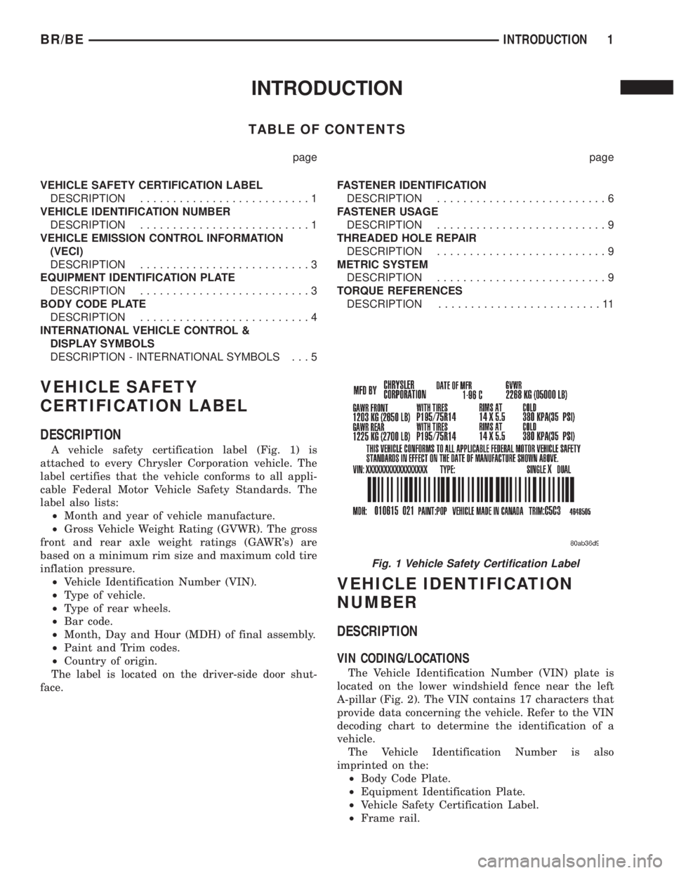
A vehicle safety certification label (Fig. 1) is
attached to every Chrysler Corporation vehicle. The
label certifies that the vehicle conforms to all appli-
cable Federal Motor Vehicle Safety Standards. The
label also lists:
²Month and year of vehicle manufacture.
²Gross Vehicle Weight Rating (GVWR). The gross
front and rear axle weight ratings (GAWR's) are
based on a minimum rim size and maximum cold tire
inflation pressure.
²Vehicle Identification Number (VIN).
²Type of vehicle.
²Type of rear wheels.
²Bar code.
²Month, Day and Hour (MDH) of final assembly.
²Paint and Trim codes.
²Country of origin.
The label is located on the driver-side door shut-
face.
VEHICLE IDENTIFICATION
NUMBER
DESCRIPTION
VIN CODING/LOCATIONS
The Vehicle Identification Number (VIN) plate is
located on the lower windshield fence near the left
A-pillar (Fig. 2). The VIN contains 17 characters that
provide data concerning the vehicle. Refer to the VIN
decoding chart to determine the identification of a
vehicle.
The Vehicle Identification Number is also
imprinted on the:
²Body Code Plate.
²Equipment Identification Plate.
²Vehicle Safety Certification Label.
²Frame rail.
Fig. 1 Vehicle Safety Certification Label
BR/BEINTRODUCTION 1
Page 4 of 2255
VEHICLE EMISSION CONTROL
INFORMATION (VECI)
DESCRIPTION
Vehicles equipped with 5.9L V-8 LDC-gas powered
engines have a vehicle emission control information
(VECI) label.
The label combines both emission control informa-
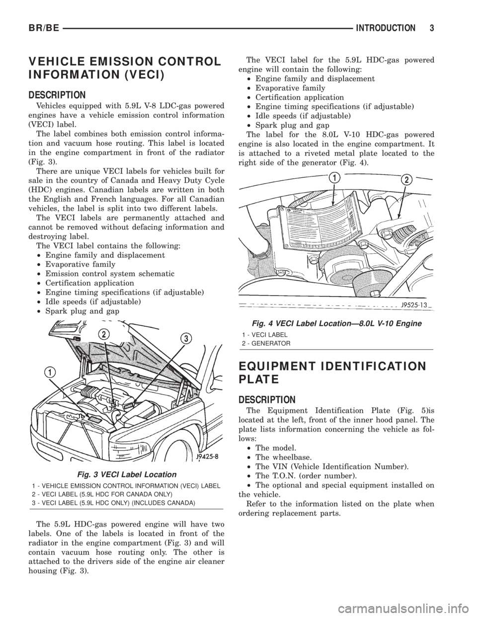
tion and vacuum hose routing. This label is located
in the engine compartment in front of the radiator
(Fig. 3).
There are unique VECI labels for vehicles built for
sale in the country of Canada and Heavy Duty Cycle
(HDC) engines. Canadian labels are written in both
the English and French languages. For all Canadian
vehicles, the label is split into two different labels.
The VECI labels are permanently attached and
cannot be removed without defacing information and
destroying label.
The VECI label contains the following:
²Engine family and displacement
²Evaporative family
²Emission control system schematic
²Certification application
²Engine timing specifications (if adjustable)
²Idle speeds (if adjustable)
²Spark plug and gap
The 5.9L HDC-gas powered engine will have two
labels. One of the labels is located in front of the
radiator in the engine compartment (Fig. 3) and will
contain vacuum hose routing only. The other is
attached to the drivers side of the engine air cleaner
housing (Fig. 3).The VECI label for the 5.9L HDC-gas powered
engine will contain the following:
²Engine family and displacement
²Evaporative family
²Certification application
²Engine timing specifications (if adjustable)
²Idle speeds (if adjustable)
²Spark plug and gap
The label for the 8.0L V-10 HDC-gas powered
engine is also located in the engine compartment. It
is attached to a riveted metal plate located to the
right side of the generator (Fig. 4).
EQUIPMENT IDENTIFICATION
PLATE
DESCRIPTION
The Equipment Identification Plate (Fig. 5)is
located at the left, front of the inner hood panel. The
plate lists information concerning the vehicle as fol-
lows:
²The model.
²The wheelbase.
²The VIN (Vehicle Identification Number).
²The T.O.N. (order number).
²The optional and special equipment installed on
the vehicle.
Refer to the information listed on the plate when
ordering replacement parts.
Fig. 3 VECI Label Location
1 - VEHICLE EMISSION CONTROL INFORMATION (VECI) LABEL
2 - VECI LABEL (5.9L HDC FOR CANADA ONLY)
3 - VECI LABEL (5.9L HDC ONLY) (INCLUDES CANADA)
Fig. 4 VECI Label LocationÐ8.0L V-10 Engine
1 - VECI LABEL
2 - GENERATOR
BR/BEINTRODUCTION 3
Page 5 of 2255
BODY CODE PLATE
DESCRIPTION
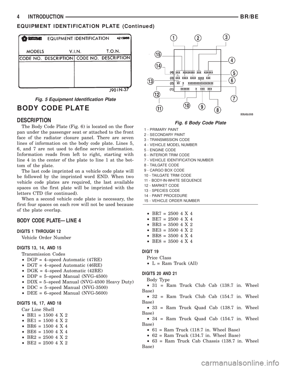
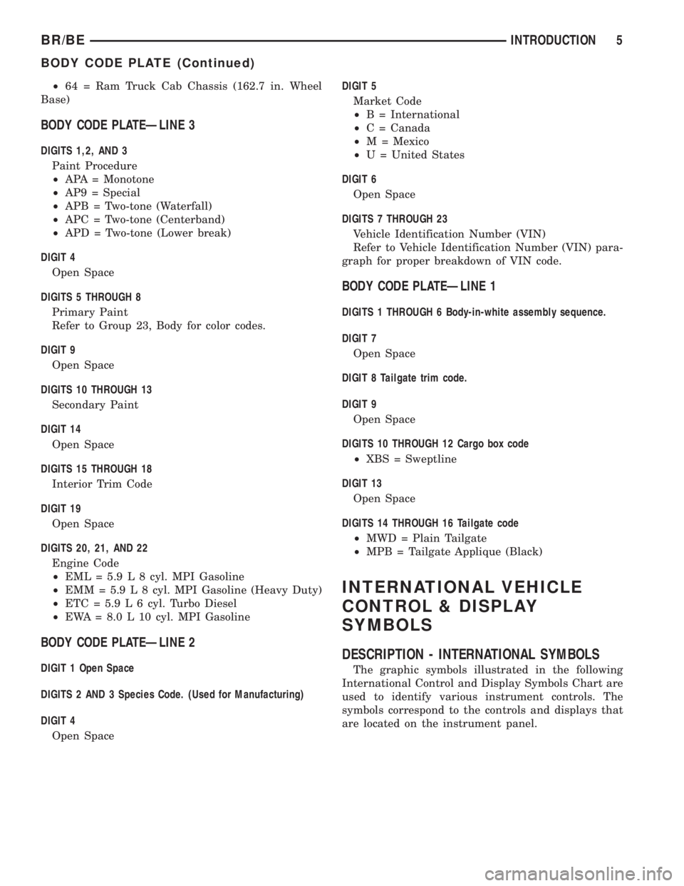
The Body Code Plate (Fig. 6) is located on the floor
pan under the passenger seat or attached to the front
face of the radiator closure panel. There are seven
lines of information on the body code plate. Lines 5,
6, and 7 are not used to define service information.
Information reads from left to right, starting with
line 4 in the center of the plate to line 1 at the bot-
tom of the plate.
The last code imprinted on a vehicle code plate will
be followed by the imprinted word END. When two
vehicle code plates are required, the last available
spaces on the first plate will be imprinted with the
letters CTD (for continued).
When a second vehicle code plate is necessary, the
first four spaces on each row will not be used because
of the plate overlap.
BODY CODE PLATEÐLINE 4
DIGITS 1 THROUGH 12
Vehicle Order Number
DIGITS 13, 14, AND 15
Transmission Codes
²DGP = 4±speed Automatic (47RE)
²DGT = 4±speed Automatic (46RE)
²DGK = 4±speed Automatic (42RE)
²DDP = 5±speed Manual (NVG-4500)
²DDX = 5±speed Manual (NVG-4500 Heavy Duty)
²DDC = 5±speed Manual (NVG-3500)
²DEE = 6±speed Manual (NVG-5600)
DIGITS 16, 17, AND 18
Car Line Shell
²BR1=15004X2
²BE1=15004X2
²BR6=15004X4
²BE6=15004X4
²BR2=25004X2
²BE2=25004X2²BR7=25004X4
²BE7=25004X4
²BR3=35004X2
²BE3=35004X2
²BR8=35004X4
²BE8=35004X4
DIGIT 19
Price Class
²L = Ram Truck (All)
DIGITS 20 AND 21
Body Type
²31 = Ram Truck Club Cab (138.7 in. Wheel
Base)
²32 = Ram Truck Club Cab (154.7 in. Wheel
Base)
²33 = Ram Truck Quad Cab (138.7 in. Wheel
Base)
²34 = Ram Truck Quad Cab (154.7 in. Wheel
Base)
²61 = Ram Truck (118.7 in. Wheel Base)
²62 = Ram Truck (134.7 in. Wheel Base)
²63 = Ram Truck Cab Chassis (138.7 in. Wheel
Base)
Fig. 5 Equipment Identification Plate
Fig. 6 Body Code Plate
1 - PRIMARY PAINT
2 - SECONDARY PAINT
3 - TRANSMISSION CODE
4 - VEHICLE MODEL NUMBER
5 - ENGINE CODE
6 - INTERIOR TRIM CODE
7 - VEHICLE IDENTIFICATION NUMBER
8 - TAILGATE CODE
9 - CARGO BOX CODE
10 - TAILGATE TRIM CODE
11 - BODY-IN-WHITE SEQUENCE
12 - MARKET CODE
13 - SPECIES CODE
14 - PAINT PROCEDURE
15 - VEHICLE ORDER NUMBER
4 INTRODUCTIONBR/BE
EQUIPMENT IDENTIFICATION PLATE (Continued)
Page 6 of 2255
²64 = Ram Truck Cab Chassis (162.7 in. Wheel
Base)
BODY CODE PLATEÐLINE 3
DIGITS 1,2, AND 3
Paint Procedure
²APA = Monotone
²AP9 = Special
²APB = Two-tone (Waterfall)
²APC = Two-tone (Centerband)
²APD = Two-tone (Lower break)
DIGIT 4
Open Space
DIGITS 5 THROUGH 8
Primary Paint
Refer to Group 23, Body for color codes.
DIGIT 9
Open Space
DIGITS 10 THROUGH 13
Secondary Paint
DIGIT 14
Open Space
DIGITS 15 THROUGH 18
Interior Trim Code
DIGIT 19
Open Space
DIGITS 20, 21, AND 22
Engine Code
²EML = 5.9 L 8 cyl. MPI Gasoline
²EMM = 5.9 L 8 cyl. MPI Gasoline (Heavy Duty)
²ETC = 5.9 L 6 cyl. Turbo Diesel
²EWA = 8.0 L 10 cyl. MPI Gasoline
BODY CODE PLATEÐLINE 2
DIGIT 1 Open Space
DIGITS 2 AND 3 Species Code. (Used for Manufacturing)
DIGIT 4
Open SpaceDIGIT 5
Market Code
²B = International
²C = Canada
²M = Mexico
²U = United States
DIGIT 6
Open Space
DIGITS 7 THROUGH 23
Vehicle Identification Number (VIN)
Refer to Vehicle Identification Number (VIN) para-
graph for proper breakdown of VIN code.
BODY CODE PLATEÐLINE 1
DIGITS 1 THROUGH 6 Body-in-white assembly sequence.
DIGIT 7
Open Space
DIGIT 8 Tailgate trim code.
DIGIT 9
Open Space
DIGITS 10 THROUGH 12 Cargo box code
²XBS = Sweptline
DIGIT 13
Open Space
DIGITS 14 THROUGH 16 Tailgate code
²MWD = Plain Tailgate
²MPB = Tailgate Applique (Black)
INTERNATIONAL VEHICLE
CONTROL & DISPLAY
SYMBOLS
DESCRIPTION - INTERNATIONAL SYMBOLS
The graphic symbols illustrated in the following
International Control and Display Symbols Chart are
used to identify various instrument controls. The
symbols correspond to the controls and displays that
are located on the instrument panel.
BR/BEINTRODUCTION 5
BODY CODE PLATE (Continued)
Page 14 of 2255
LUBRICATION & MAINTENANCE
TABLE OF CONTENTS
page page
INTERNATIONAL SYMBOLS
DESCRIPTION...........................1
PARTS & LUBRICANT RECOMMENDATION
STANDARD PROCEDURE
STANDARD PROCEDURE -
CLASSIFICATION OF LUBRICANTS..........1
FLUID TYPES
DESCRIPTION...........................2
OPERATION.............................6
FLUID CAPACITIES
SPECIFICATIONS.........................6
MAINTENANCE SCHEDULES
DESCRIPTION...........................7JUMP STARTING
STANDARD PROCEDURE
STANDARD PROCEDURE - JUMP
STARTING.............................7
HOISTING
STANDARD PROCEDURE
STANDARD PROCEDURE - HOISTING.......9
TOWING
STANDARD PROCEDURE
STANDARD PROCEDURE - TOWING.......10
INTERNATIONAL SYMBOLS
DESCRIPTION
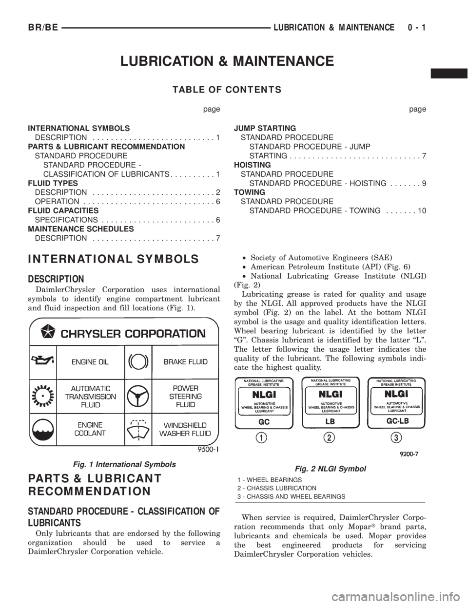
DaimlerChrysler Corporation uses international
symbols to identify engine compartment lubricant
and fluid inspection and fill locations (Fig. 1).
PARTS & LUBRICANT
RECOMMENDATION
STANDARD PROCEDURE - CLASSIFICATION OF
LUBRICANTS
Only lubricants that are endorsed by the following
organization should be used to service a
DaimlerChrysler Corporation vehicle.²Society of Automotive Engineers (SAE)
²American Petroleum Institute (API) (Fig. 6)
²National Lubricating Grease Institute (NLGI)
(Fig. 2)
Lubricating grease is rated for quality and usage
by the NLGI. All approved products have the NLGI
symbol (Fig. 2) on the label. At the bottom NLGI
symbol is the usage and quality identification letters.
Wheel bearing lubricant is identified by the letter
ªGº. Chassis lubricant is identified by the latter ªLº.
The letter following the usage letter indicates the
quality of the lubricant. The following symbols indi-
cate the highest quality.
When service is required, DaimlerChrysler Corpo-
ration recommends that only Mopartbrand parts,
lubricants and chemicals be used. Mopar provides
the best engineered products for servicing
DaimlerChrysler Corporation vehicles.
Fig. 1 International SymbolsFig. 2 NLGI Symbol
1 - WHEEL BEARINGS
2 - CHASSIS LUBRICATION
3 - CHASSIS AND WHEEL BEARINGS
BR/BELUBRICATION & MAINTENANCE 0 - 1
Page 23 of 2255
TOWING
STANDARD PROCEDURE - TOWING
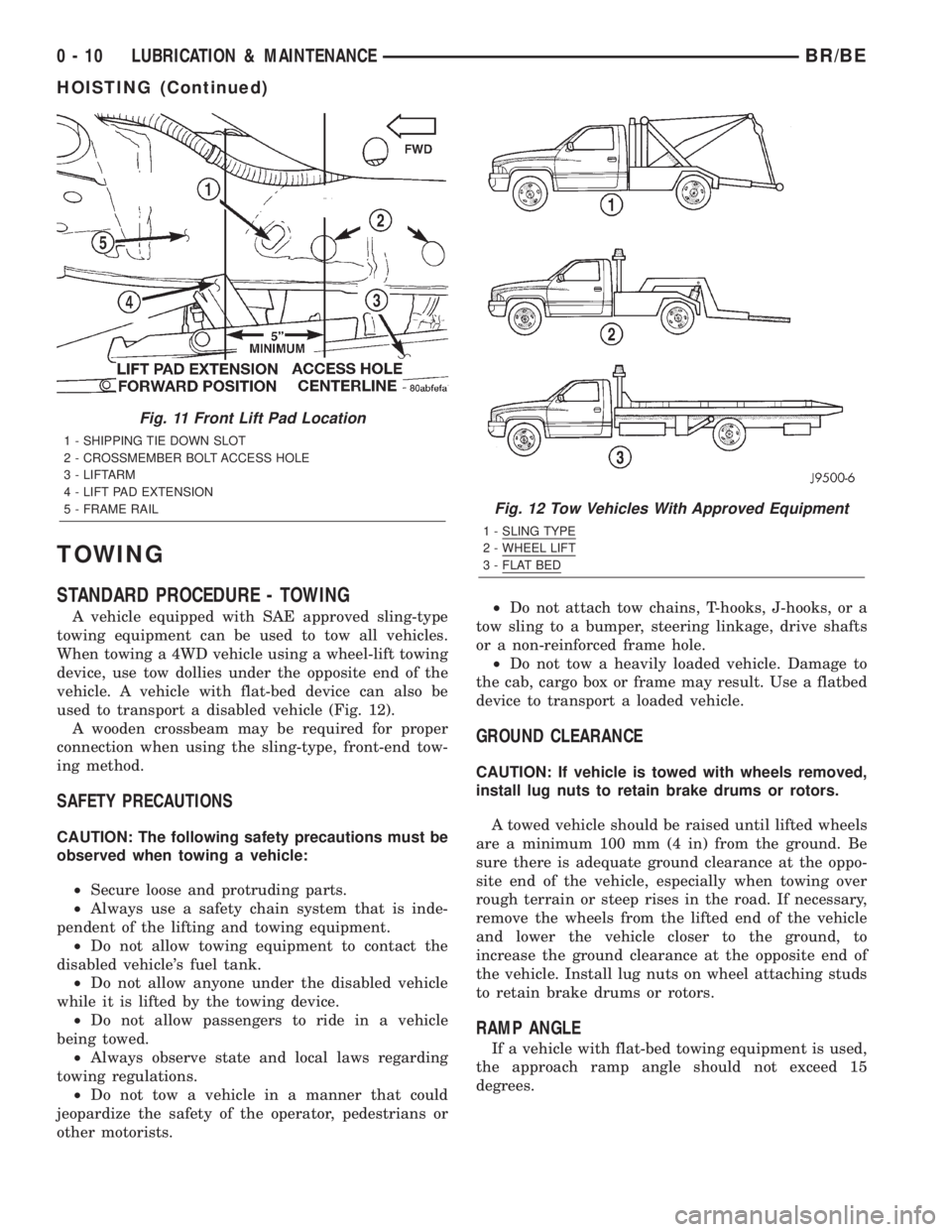
A vehicle equipped with SAE approved sling-type
towing equipment can be used to tow all vehicles.
When towing a 4WD vehicle using a wheel-lift towing
device, use tow dollies under the opposite end of the
vehicle. A vehicle with flat-bed device can also be
used to transport a disabled vehicle (Fig. 12).
A wooden crossbeam may be required for proper
connection when using the sling-type, front-end tow-
ing method.
SAFETY PRECAUTIONS
CAUTION: The following safety precautions must be
observed when towing a vehicle:
²Secure loose and protruding parts.
²Always use a safety chain system that is inde-
pendent of the lifting and towing equipment.
²Do not allow towing equipment to contact the
disabled vehicle's fuel tank.
²Do not allow anyone under the disabled vehicle
while it is lifted by the towing device.
²Do not allow passengers to ride in a vehicle
being towed.
²Always observe state and local laws regarding
towing regulations.
²Do not tow a vehicle in a manner that could
jeopardize the safety of the operator, pedestrians or
other motorists.²Do not attach tow chains, T-hooks, J-hooks, or a
tow sling to a bumper, steering linkage, drive shafts
or a non-reinforced frame hole.
²Do not tow a heavily loaded vehicle. Damage to
the cab, cargo box or frame may result. Use a flatbed
device to transport a loaded vehicle.
GROUND CLEARANCE
CAUTION: If vehicle is towed with wheels removed,
install lug nuts to retain brake drums or rotors.
A towed vehicle should be raised until lifted wheels
are a minimum 100 mm (4 in) from the ground. Be
sure there is adequate ground clearance at the oppo-
site end of the vehicle, especially when towing over
rough terrain or steep rises in the road. If necessary,
remove the wheels from the lifted end of the vehicle
and lower the vehicle closer to the ground, to
increase the ground clearance at the opposite end of
the vehicle. Install lug nuts on wheel attaching studs
to retain brake drums or rotors.
RAMP ANGLE
If a vehicle with flat-bed towing equipment is used,
the approach ramp angle should not exceed 15
degrees.
Fig. 11 Front Lift Pad Location
1 - SHIPPING TIE DOWN SLOT
2 - CROSSMEMBER BOLT ACCESS HOLE
3 - LIFTARM
4 - LIFT PAD EXTENSION
5 - FRAME RAIL
Fig. 12 Tow Vehicles With Approved Equipment
1 - SLING TYPE
2 - WHEEL LIFT
3 - FLAT BED
0 - 10 LUBRICATION & MAINTENANCEBR/BE
HOISTING (Continued)
Page 24 of 2255
TOWING WHEN KEYS ARE NOT AVAILABLE
When the vehicle is locked and keys are not avail-
able, use a flat bed hauler. A Wheel-lift or Sling-type
device can be used on 4WD vehicles providedall the
wheels are lifted off the ground using tow dol-
lies.
FOUR-WHEEL-DRIVE VEHICLE TOWING
Chrysler Corporation recommends that a vehicle be
transported on a flat-bed device. A Wheel-lift or
Sling-type device can be used providedall the
wheels are lifted off the ground using tow dol-
lies.WARNING: WHEN TOWING A DISABLED VEHICLE
AND THE DRIVE WHEELS ARE SECURED IN A
WHEEL LIFT OR TOW DOLLIES, ENSURE THE
TRANSMISSION IS IN THE PARK POSITION (AUTO-
MATIC TRANSMISSION) OR A FORWARD DRIVE
GEAR (MANUAL TRANSMISSION).
CAUTION: Many vehicles are equipped with air
dams, spoilers, and/or ground effect panels. To
avoid component damage, a wheel-lift towing vehi-
cle or a flat-bed hauling vehicle is recommended.
BR/BELUBRICATION & MAINTENANCE 0 - 11
TOWING (Continued)
Page 26 of 2255
SUSPENSION
TABLE OF CONTENTS
page page
WHEEL ALIGNMENT......................1
FRONT - 2WD............................7FRONT - 4WD...........................14
REAR.................................25
WHEEL ALIGNMENT
TABLE OF CONTENTS
page page
WHEEL ALIGNMENT
DESCRIPTION..........................1
OPERATION............................2
DIAGNOSIS AND TESTING - PRE-ALIGNMENT . 2
STANDARD PROCEDURE
STANDARD PROCEDURES - ALIGNMENT
I.F.S. ................................3STANDARD PROCEDURE - CASTER
CORRECTION MEASUREMENT...........3
STANDARD PROCEDURE - ALIGNMENT
LINK/COIL SUSPENSION.................5
SPECIFICATIONS
ALIGNMENT..........................6
WHEEL ALIGNMENT
DESCRIPTION
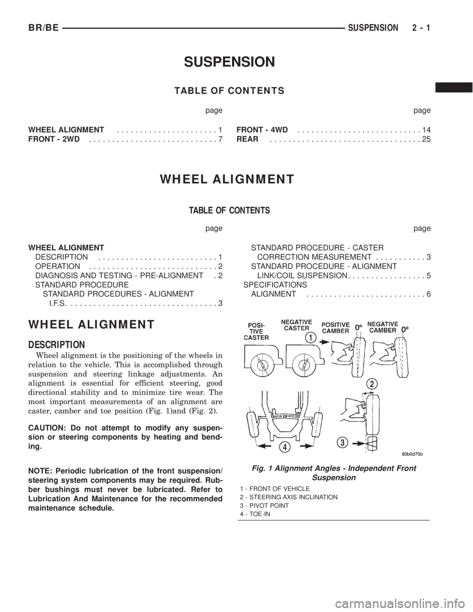
Wheel alignment is the positioning of the wheels in
relation to the vehicle. This is accomplished through
suspension and steering linkage adjustments. An
alignment is essential for efficient steering, good
directional stability and to minimize tire wear. The
most important measurements of an alignment are
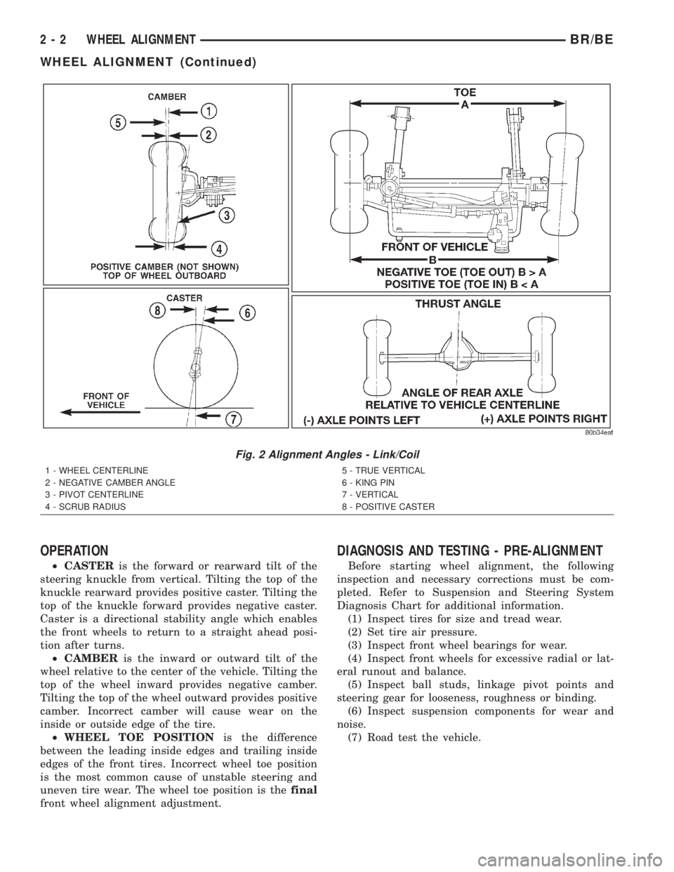
caster, camber and toe position (Fig. 1)and (Fig. 2).
CAUTION: Do not attempt to modify any suspen-
sion or steering components by heating and bend-
ing.
NOTE: Periodic lubrication of the front suspension/
steering system components may be required. Rub-
ber bushings must never be lubricated. Refer to
Lubrication And Maintenance for the recommended
maintenance schedule.
Fig. 1 Alignment Angles - Independent Front
Suspension
1 - FRONT OF VEHICLE
2 - STEERING AXIS INCLINATION
3 - PIVOT POINT
4 - TOE-IN
BR/BESUSPENSION 2 - 1
Page 27 of 2255
OPERATION
²CASTERis the forward or rearward tilt of the
steering knuckle from vertical. Tilting the top of the
knuckle rearward provides positive caster. Tilting the
top of the knuckle forward provides negative caster.
Caster is a directional stability angle which enables
the front wheels to return to a straight ahead posi-
tion after turns.
²CAMBERis the inward or outward tilt of the
wheel relative to the center of the vehicle. Tilting the
top of the wheel inward provides negative camber.
Tilting the top of the wheel outward provides positive
camber. Incorrect camber will cause wear on the
inside or outside edge of the tire.
²WHEEL TOE POSITIONis the difference
between the leading inside edges and trailing inside
edges of the front tires. Incorrect wheel toe position
is the most common cause of unstable steering and
uneven tire wear. The wheel toe position is thefinal
front wheel alignment adjustment.
DIAGNOSIS AND TESTING - PRE-ALIGNMENT
Before starting wheel alignment, the following
inspection and necessary corrections must be com-
pleted. Refer to Suspension and Steering System
Diagnosis Chart for additional information.
(1) Inspect tires for size and tread wear.
(2) Set tire air pressure.
(3) Inspect front wheel bearings for wear.
(4) Inspect front wheels for excessive radial or lat-
eral runout and balance.
(5) Inspect ball studs, linkage pivot points and
steering gear for looseness, roughness or binding.
(6) Inspect suspension components for wear and
noise.
(7) Road test the vehicle.
Fig. 2 Alignment Angles - Link/Coil
1 - WHEEL CENTERLINE
2 - NEGATIVE CAMBER ANGLE
3 - PIVOT CENTERLINE
4 - SCRUB RADIUS5 - TRUE VERTICAL
6 - KING PIN
7 - VERTICAL
8 - POSITIVE CASTER
2 - 2 WHEEL ALIGNMENTBR/BE
WHEEL ALIGNMENT (Continued)