sensor DODGE RAM 2002 Service Owner's Manual
[x] Cancel search | Manufacturer: DODGE, Model Year: 2002, Model line: RAM, Model: DODGE RAM 2002Pages: 2255, PDF Size: 62.07 MB
Page 263 of 2255
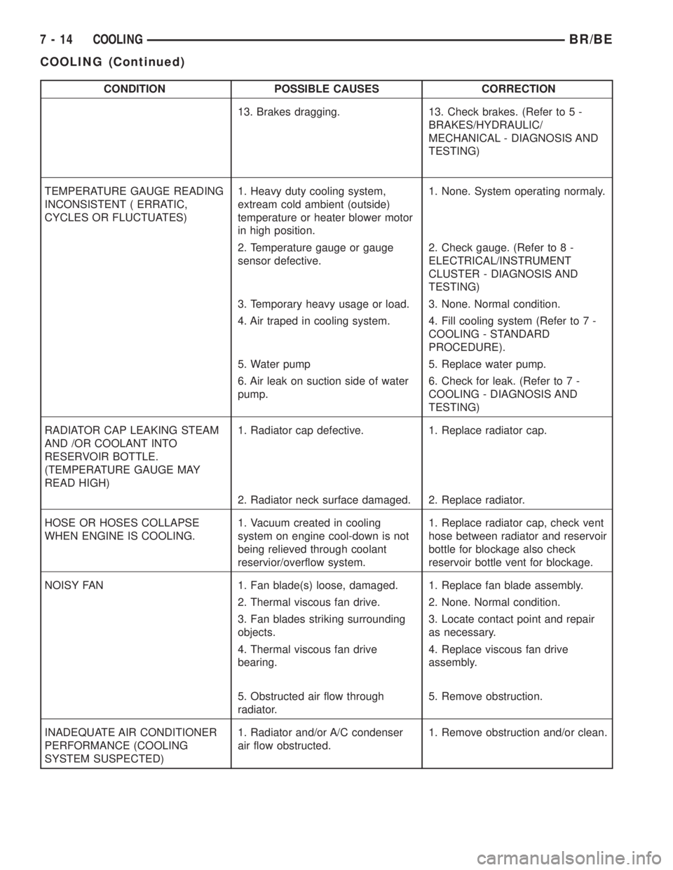
CONDITION POSSIBLE CAUSES CORRECTION
13. Brakes dragging. 13. Check brakes. (Refer to 5 -
BRAKES/HYDRAULIC/
MECHANICAL - DIAGNOSIS AND
TESTING)
TEMPERATURE GAUGE READING
INCONSISTENT ( ERRATIC,
CYCLES OR FLUCTUATES)1. Heavy duty cooling system,
extream cold ambient (outside)
temperature or heater blower motor
in high position.1. None. System operating normaly.
2. Temperature gauge or gauge
sensor defective.2. Check gauge. (Refer to 8 -
ELECTRICAL/INSTRUMENT
CLUSTER - DIAGNOSIS AND
TESTING)
3. Temporary heavy usage or load. 3. None. Normal condition.
4. Air traped in cooling system. 4. Fill cooling system (Refer to 7 -
COOLING - STANDARD
PROCEDURE).
5. Water pump 5. Replace water pump.
6. Air leak on suction side of water
pump.6. Check for leak. (Refer to 7 -
COOLING - DIAGNOSIS AND
TESTING)
RADIATOR CAP LEAKING STEAM
AND /OR COOLANT INTO
RESERVOIR BOTTLE.
(TEMPERATURE GAUGE MAY
READ HIGH)1. Radiator cap defective. 1. Replace radiator cap.
2. Radiator neck surface damaged. 2. Replace radiator.
HOSE OR HOSES COLLAPSE
WHEN ENGINE IS COOLING.1. Vacuum created in cooling
system on engine cool-down is not
being relieved through coolant
reservior/overflow system.1. Replace radiator cap, check vent
hose between radiator and reservoir
bottle for blockage also check
reservoir bottle vent for blockage.
NOISY FAN 1. Fan blade(s) loose, damaged. 1. Replace fan blade assembly.
2. Thermal viscous fan drive. 2. None. Normal condition.
3. Fan blades striking surrounding
objects.3. Locate contact point and repair
as necessary.
4. Thermal viscous fan drive
bearing.4. Replace viscous fan drive
assembly.
5. Obstructed air flow through
radiator.5. Remove obstruction.
INADEQUATE AIR CONDITIONER
PERFORMANCE (COOLING
SYSTEM SUSPECTED)1. Radiator and/or A/C condenser
air flow obstructed.1. Remove obstruction and/or clean.
7 - 14 COOLINGBR/BE
COOLING (Continued)
Page 287 of 2255
ENGINE
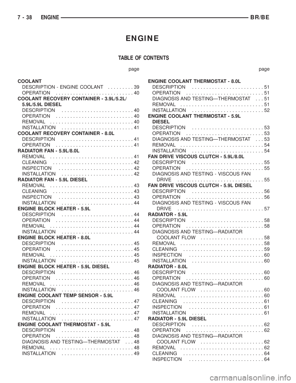
TABLE OF CONTENTS
page page
COOLANT
DESCRIPTION - ENGINE COOLANT.........39
OPERATION...........................40
COOLANT RECOVERY CONTAINER - 3.9L/5.2L/
5.9L/5.9L DIESEL
DESCRIPTION.........................40
OPERATION...........................40
REMOVAL.............................40
INSTALLATION.........................41
COOLANT RECOVERY CONTAINER - 8.0L
DESCRIPTION.........................41
OPERATION...........................41
RADIATOR FAN - 5.9L/8.0L
REMOVAL.............................41
CLEANING............................42
INSPECTION..........................42
INSTALLATION.........................42
RADIATOR FAN - 5.9L DIESEL
REMOVAL.............................43
CLEANING............................43
INSPECTION..........................43
INSTALLATION.........................44
ENGINE BLOCK HEATER - 5.9L
DESCRIPTION.........................44
OPERATION...........................44
REMOVAL.............................44
INSTALLATION.........................44
ENGINE BLOCK HEATER - 8.0L
DESCRIPTION.........................45
OPERATION...........................45
REMOVAL.............................45
INSTALLATION.........................45
ENGINE BLOCK HEATER - 5.9L DIESEL
DESCRIPTION.........................46
OPERATION...........................46
REMOVAL.............................46
INSTALLATION.........................46
ENGINE COOLANT TEMP SENSOR - 5.9L
DESCRIPTION.........................47
OPERATION...........................47
REMOVAL.............................47
INSTALLATION.........................47
ENGINE COOLANT THERMOSTAT - 5.9L
DESCRIPTION.........................48
OPERATION...........................48
DIAGNOSIS AND TESTINGÐTHERMOSTAT . . . 48
REMOVAL.............................48
INSTALLATION.........................49ENGINE COOLANT THERMOSTAT - 8.0L
DESCRIPTION.........................51
OPERATION...........................51
DIAGNOSIS AND TESTINGÐTHERMOSTAT . . . 51
REMOVAL.............................51
INSTALLATION.........................52
ENGINE COOLANT THERMOSTAT - 5.9L
DIESEL
DESCRIPTION.........................53
OPERATION...........................53
DIAGNOSIS AND TESTINGÐTHERMOSTAT . . . 53
REMOVAL.............................54
INSTALLATION.........................54
FAN DRIVE VISCOUS CLUTCH - 5.9L/8.0L
DESCRIPTION.........................55
OPERATION...........................55
DIAGNOSIS AND TESTING - VISCOUS FAN
DRIVE..............................55
FAN DRIVE VISCOUS CLUTCH - 5.9L DIESEL
DESCRIPTION.........................56
OPERATION...........................56
DIAGNOSIS AND TESTING - VISCOUS FAN
DRIVE..............................57
RADIATOR - 5.9L
DESCRIPTION.........................58
OPERATION...........................58
DIAGNOSIS AND TESTINGÐRADIATOR
COOLANT FLOW......................58
REMOVAL.............................58
CLEANING............................59
INSPECTION..........................60
INSTALLATION.........................60
RADIATOR - 8.0L
DESCRIPTION.........................60
OPERATION...........................60
DIAGNOSIS AND TESTINGÐRADIATOR
COOLANT FLOW......................60
REMOVAL.............................60
CLEANING............................61
INSPECTION..........................61
INSTALLATION.........................61
RADIATOR - 5.9L DIESEL
DESCRIPTION.........................62
OPERATION...........................62
DIAGNOSIS AND TESTINGÐRADIATOR
COOLANT FLOW......................62
REMOVAL.............................62
CLEANING............................64
INSPECTION..........................64
7 - 38 ENGINEBR/BE
Page 296 of 2255
ENGINE COOLANT TEMP
SENSOR - 5.9L
DESCRIPTION
The Engine Coolant Temperature (ECT) sensor is
used to sense engine coolant temperature. The sensor
protrudes into an engine water jacket.
The ECT sensor is a two-wire Negative Thermal
Coefficient (NTC) sensor. Meaning, as engine coolant
temperature increases, resistance (voltage) in the
sensor decreases. As temperature decreases, resis-
tance (voltage) in the sensor increases.
OPERATION
At key-on, the Powertrain Control Module (PCM)
sends out a regulated 5 volt signal to the ECT sensor.
The PCM then monitors the signal as it passes
through the ECT sensor to the sensor ground (sensor
return).
When the engine is cold, the PCM will operate in
Open Loop cycle. It will demand slightly richer air-
fuel mixtures and higher idle speeds. This is done
until normal operating temperatures are reached.
The PCM uses inputs from the ECT sensor for the
following calculations:
²for engine coolant temperature gauge operation
through CCD or PCI (J1850) communications
²Injector pulse-width
²Spark-advance curves
²ASD relay shut-down times
²Idle Air Control (IAC) motor key-on steps
²Pulse-width prime-shot during cranking
²O2 sensor closed loop times
²Purge solenoid on/off times
²EGR solenoid on/off times (if equipped)
²Leak Detection Pump operation (if equipped)
²Radiator fan relay on/off times (if equipped)²Target idle speed
REMOVAL
WARNING: HOT, PRESSURIZED COOLANT CAN
CAUSE INJURY BY SCALDING. COOLING SYSTEM
MUST BE PARTIALLY DRAINED BEFORE REMOV-
ING THE COOLANT TEMPERATURE SENSOR.
REFER TO GROUP 7, COOLING.
(1) Partially drain cooling system (Refer to 7 -
COOLING - STANDARD PROCEDURE).
(2) Remove air cleaner assembly.
(3) Disconnect electrical connector from sensor
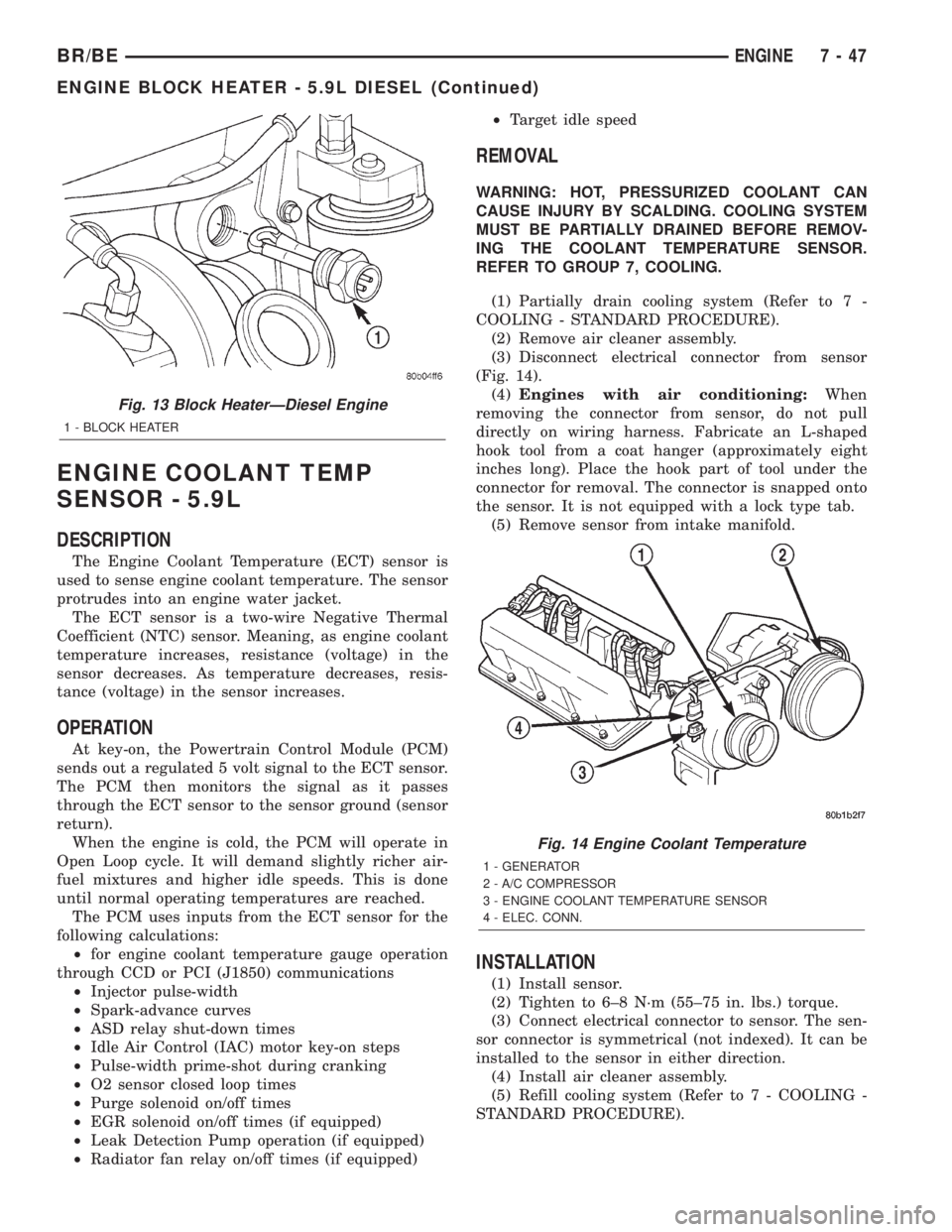
(Fig. 14).
(4)Engines with air conditioning:When
removing the connector from sensor, do not pull
directly on wiring harness. Fabricate an L-shaped
hook tool from a coat hanger (approximately eight
inches long). Place the hook part of tool under the
connector for removal. The connector is snapped onto
the sensor. It is not equipped with a lock type tab.
(5) Remove sensor from intake manifold.
INSTALLATION
(1) Install sensor.
(2) Tighten to 6±8 N´m (55±75 in. lbs.) torque.
(3) Connect electrical connector to sensor. The sen-
sor connector is symmetrical (not indexed). It can be
installed to the sensor in either direction.
(4) Install air cleaner assembly.
(5) Refill cooling system (Refer to 7 - COOLING -
STANDARD PROCEDURE).
Fig. 13 Block HeaterÐDiesel Engine
1 - BLOCK HEATER
Fig. 14 Engine Coolant Temperature
1 - GENERATOR
2 - A/C COMPRESSOR
3 - ENGINE COOLANT TEMPERATURE SENSOR
4 - ELEC. CONN.
BR/BEENGINE 7 - 47
ENGINE BLOCK HEATER - 5.9L DIESEL (Continued)
Page 300 of 2255
ENGINE COOLANT
THERMOSTAT - 8.0L
DESCRIPTION
CAUTION: Do not operate an engine without a ther-
mostat, except for servicing or testing.
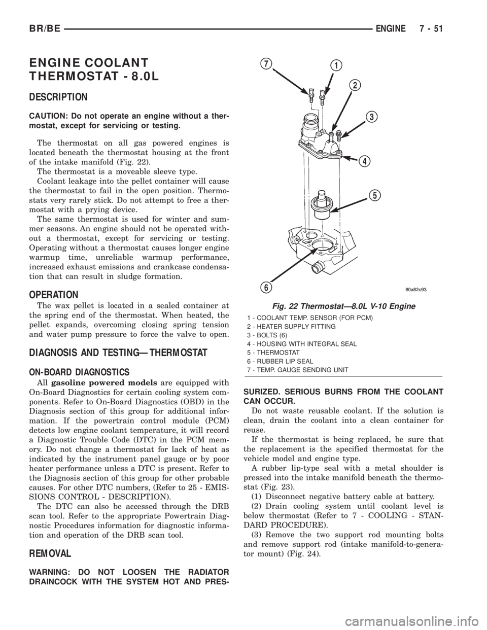
The thermostat on all gas powered engines is
located beneath the thermostat housing at the front
of the intake manifold (Fig. 22).
The thermostat is a moveable sleeve type.
Coolant leakage into the pellet container will cause
the thermostat to fail in the open position. Thermo-
stats very rarely stick. Do not attempt to free a ther-
mostat with a prying device.
The same thermostat is used for winter and sum-
mer seasons. An engine should not be operated with-
out a thermostat, except for servicing or testing.
Operating without a thermostat causes longer engine
warmup time, unreliable warmup performance,
increased exhaust emissions and crankcase condensa-
tion that can result in sludge formation.
OPERATION
The wax pellet is located in a sealed container at
the spring end of the thermostat. When heated, the
pellet expands, overcoming closing spring tension
and water pump pressure to force the valve to open.
DIAGNOSIS AND TESTINGÐTHERMOSTAT
ON-BOARD DIAGNOSTICS
Allgasoline powered modelsare equipped with
On-Board Diagnostics for certain cooling system com-
ponents. Refer to On-Board Diagnostics (OBD) in the
Diagnosis section of this group for additional infor-
mation. If the powertrain control module (PCM)
detects low engine coolant temperature, it will record
a Diagnostic Trouble Code (DTC) in the PCM mem-
ory. Do not change a thermostat for lack of heat as
indicated by the instrument panel gauge or by poor
heater performance unless a DTC is present. Refer to
the Diagnosis section of this group for other probable
causes. For other DTC numbers, (Refer to 25 - EMIS-
SIONS CONTROL - DESCRIPTION).
The DTC can also be accessed through the DRB
scan tool. Refer to the appropriate Powertrain Diag-
nostic Procedures information for diagnostic informa-
tion and operation of the DRB scan tool.
REMOVAL
WARNING: DO NOT LOOSEN THE RADIATOR
DRAINCOCK WITH THE SYSTEM HOT AND PRES-SURIZED. SERIOUS BURNS FROM THE COOLANT
CAN OCCUR.
Do not waste reusable coolant. If the solution is
clean, drain the coolant into a clean container for
reuse.
If the thermostat is being replaced, be sure that
the replacement is the specified thermostat for the
vehicle model and engine type.
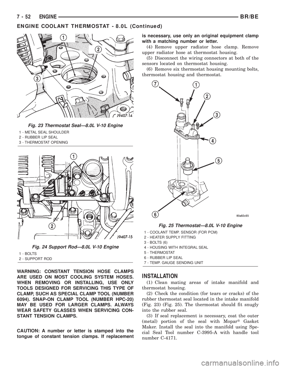
A rubber lip-type seal with a metal shoulder is
pressed into the intake manifold beneath the thermo-
stat (Fig. 23).
(1) Disconnect negative battery cable at battery.
(2) Drain cooling system until coolant level is
below thermostat (Refer to 7 - COOLING - STAN-
DARD PROCEDURE).
(3) Remove the two support rod mounting bolts
and remove support rod (intake manifold-to-genera-
tor mount) (Fig. 24).
Fig. 22 ThermostatÐ8.0L V-10 Engine
1 - COOLANT TEMP. SENSOR (FOR PCM)
2 - HEATER SUPPLY FITTING
3 - BOLTS (6)
4 - HOUSING WITH INTEGRAL SEAL
5 - THERMOSTAT
6 - RUBBER LIP SEAL
7 - TEMP. GAUGE SENDING UNIT
BR/BEENGINE 7 - 51
Page 301 of 2255
WARNING: CONSTANT TENSION HOSE CLAMPS
ARE USED ON MOST COOLING SYSTEM HOSES.
WHEN REMOVING OR INSTALLING, USE ONLY
TOOLS DESIGNED FOR SERVICING THIS TYPE OF
CLAMP, SUCH AS SPECIAL CLAMP TOOL (NUMBER
6094). SNAP-ON CLAMP TOOL (NUMBER HPC-20)
MAY BE USED FOR LARGER CLAMPS. ALWAYS
WEAR SAFETY GLASSES WHEN SERVICING CON-
STANT TENSION CLAMPS.
CAUTION: A number or letter is stamped into the
tongue of constant tension clamps. If replacementis necessary, use only an original equipment clamp
with a matching number or letter.
(4) Remove upper radiator hose clamp. Remove
upper radiator hose at thermostat housing.
(5) Disconnect the wiring connectors at both of the
sensors located on thermostat housing.
(6) Remove six thermostat housing mounting bolts,
thermostat housing and thermostat.
INSTALLATION
(1) Clean mating areas of intake manifold and
thermostat housing.
(2) Check the condition (for tears or cracks) of the
rubber thermostat seal located in the intake manifold
(Fig. 23) (Fig. 25). The thermostat should fit snugly
into the rubber seal.
(3) If seal replacement is necessary, coat the outer
(metal) portion of the seal with MopartGasket
Maker. Install the seal into the manifold using Spe-
cial Seal Tool number C-3995-A with handle tool
number C-4171.
Fig. 23 Thermostat SealÐ8.0L V-10 Engine
1 - METAL SEAL SHOULDER
2 - RUBBER LIP SEAL
3 - THERMOSTAT OPENING
Fig. 24 Support RodÐ8.0L V-10 Engine
1 - BOLTS
2 - SUPPORT ROD
Fig. 25 ThermostatÐ8.0L V-10 Engine
1 - COOLANT TEMP. SENSOR (FOR PCM)
2 - HEATER SUPPLY FITTING
3 - BOLTS (6)
4 - HOUSING WITH INTEGRAL SEAL
5 - THERMOSTAT
6 - RUBBER LIP SEAL
7 - TEMP. GAUGE SENDING UNIT
7 - 52 ENGINEBR/BE
ENGINE COOLANT THERMOSTAT - 8.0L (Continued)
Page 302 of 2255
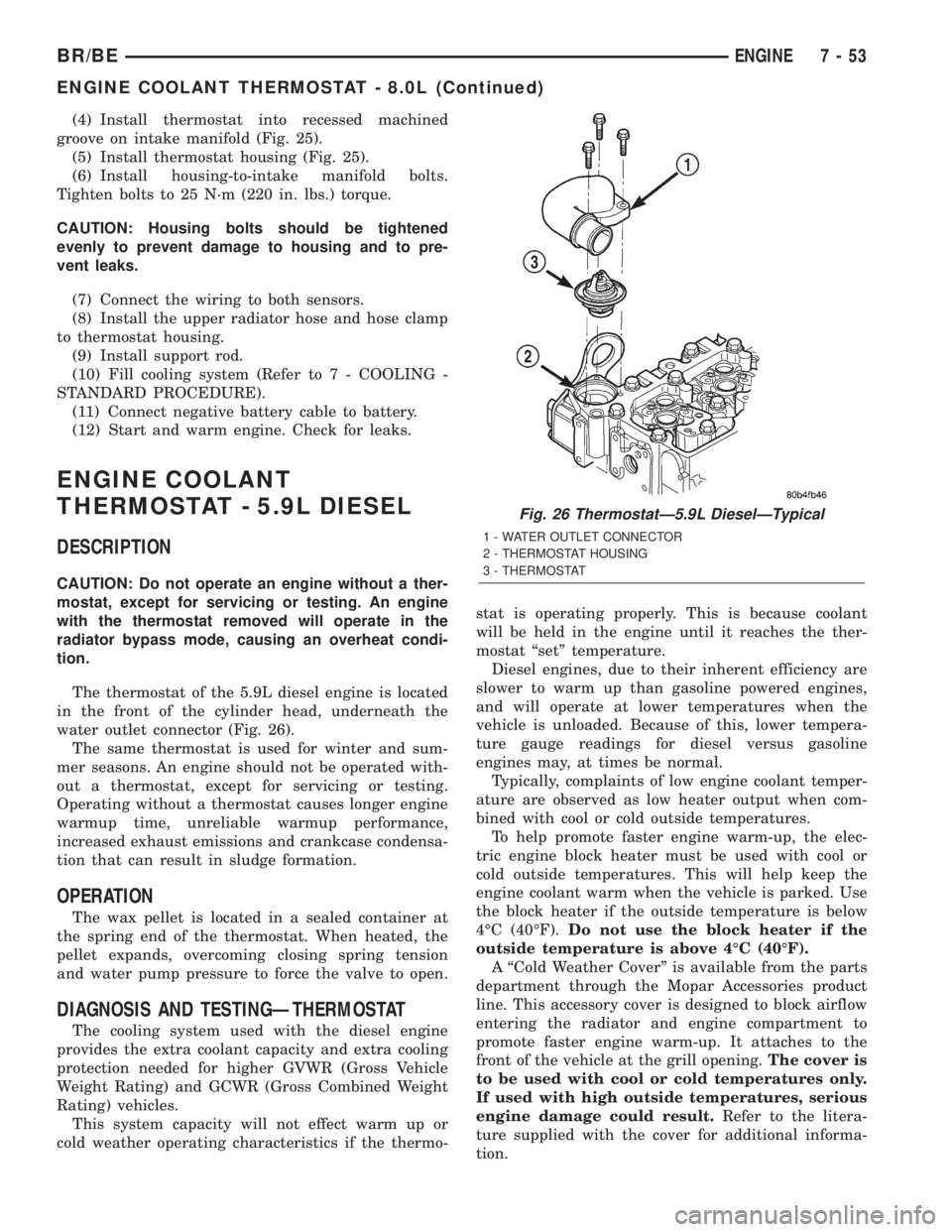
(4) Install thermostat into recessed machined
groove on intake manifold (Fig. 25).
(5) Install thermostat housing (Fig. 25).
(6) Install housing-to-intake manifold bolts.
Tighten bolts to 25 N´m (220 in. lbs.) torque.
CAUTION: Housing bolts should be tightened
evenly to prevent damage to housing and to pre-
vent leaks.
(7) Connect the wiring to both sensors.
(8) Install the upper radiator hose and hose clamp
to thermostat housing.
(9) Install support rod.
(10) Fill cooling system (Refer to 7 - COOLING -
STANDARD PROCEDURE).
(11) Connect negative battery cable to battery.
(12) Start and warm engine. Check for leaks.
ENGINE COOLANT
THERMOSTAT - 5.9L DIESEL
DESCRIPTION
CAUTION: Do not operate an engine without a ther-
mostat, except for servicing or testing. An engine
with the thermostat removed will operate in the
radiator bypass mode, causing an overheat condi-
tion.
The thermostat of the 5.9L diesel engine is located
in the front of the cylinder head, underneath the
water outlet connector (Fig. 26).
The same thermostat is used for winter and sum-
mer seasons. An engine should not be operated with-
out a thermostat, except for servicing or testing.
Operating without a thermostat causes longer engine
warmup time, unreliable warmup performance,
increased exhaust emissions and crankcase condensa-
tion that can result in sludge formation.
OPERATION
The wax pellet is located in a sealed container at
the spring end of the thermostat. When heated, the
pellet expands, overcoming closing spring tension
and water pump pressure to force the valve to open.
DIAGNOSIS AND TESTINGÐTHERMOSTAT
The cooling system used with the diesel engine
provides the extra coolant capacity and extra cooling
protection needed for higher GVWR (Gross Vehicle
Weight Rating) and GCWR (Gross Combined Weight
Rating) vehicles.
This system capacity will not effect warm up or
cold weather operating characteristics if the thermo-stat is operating properly. This is because coolant
will be held in the engine until it reaches the ther-
mostat ªsetº temperature.
Diesel engines, due to their inherent efficiency are
slower to warm up than gasoline powered engines,
and will operate at lower temperatures when the
vehicle is unloaded. Because of this, lower tempera-
ture gauge readings for diesel versus gasoline
engines may, at times be normal.
Typically, complaints of low engine coolant temper-
ature are observed as low heater output when com-
bined with cool or cold outside temperatures.
To help promote faster engine warm-up, the elec-
tric engine block heater must be used with cool or
cold outside temperatures. This will help keep the
engine coolant warm when the vehicle is parked. Use
the block heater if the outside temperature is below
4ÉC (40ÉF).Do not use the block heater if the
outside temperature is above 4ÉC (40ÉF).
A ªCold Weather Coverº is available from the parts
department through the Mopar Accessories product
line. This accessory cover is designed to block airflow
entering the radiator and engine compartment to
promote faster engine warm-up. It attaches to the
front of the vehicle at the grill opening.The cover is
to be used with cool or cold temperatures only.
If used with high outside temperatures, serious
engine damage could result.Refer to the litera-
ture supplied with the cover for additional informa-
tion.
Fig. 26 ThermostatÐ5.9L DieselÐTypical
1 - WATER OUTLET CONNECTOR
2 - THERMOSTAT HOUSING
3 - THERMOSTAT
BR/BEENGINE 7 - 53
ENGINE COOLANT THERMOSTAT - 8.0L (Continued)
Page 366 of 2255
ELECTRONIC CONTROL MODULES
TABLE OF CONTENTS
page page
CENTRAL TIMER MODULE
DESCRIPTION..........................1
OPERATION............................3
DIAGNOSIS AND TESTING - CENTRAL TIMER
MODULE.............................4
REMOVAL.............................5
INSTALLATION..........................6
COMMUNICATION
DESCRIPTION - CCD DATA BUS............6
OPERATION - CCD DATA BUS..............7
DIAGNOSIS AND TESTING - CCD DATA BUS . . 11
CONTROLLER ANTILOCK BRAKE
DESCRIPTION.........................11
OPERATION...........................11
REMOVAL.............................11
INSTALLATION.........................12
DATA LINK CONNECTOR
DESCRIPTION - DATA LINK CONNECTOR....12
OPERATION - DATA LINK CONNECTOR......12
ENGINE CONTROL MODULE
DESCRIPTION - ECM....................13
OPERATION - ECM.....................13
REMOVAL.............................14
INSTALLATION.........................14POWERTRAIN CONTROL MODULE
DESCRIPTION
DESCRIPTION - PCM..................15
DESCRIPTION - MODES OF OPERATION . . . 15
DESCRIPTION - 5 VOLT SUPPLIES.......17
DESCRIPTION - IGNITION CIRCUIT SENSE . 17
DESCRIPTION - POWER GROUNDS......17
DESCRIPTION - SENSOR RETURN.......17
DESCRIPTION - SIGNAL GROUND........17
OPERATION
OPERATION - PCM - GAS ENGINES.......18
OPERATION - DIESEL..................18
OPERATION - 5 VOLT SUPPLIES.........19
OPERATION - IGNITION CIRCUIT SENSE . . . 19
REMOVAL.............................19
INSTALLATION.........................20
HEATED SEAT MODULE
DESCRIPTION.........................20
OPERATION...........................20
DIAGNOSIS AND TESTING - HEATED SEAT
MODULE............................21
REMOVAL.............................23
INSTALLATION.........................23
CENTRAL TIMER MODULE
DESCRIPTION
Three versions of the Central Timer Module (CTM)
are available on this vehicle, a base version (Fig. 1),
a high-line version (Fig. 2), and a premium version.
Whichever version of the CTM the vehicle is
equipped with, it is concealed under the driver side
end of the instrument panel inboard of the instru-
ment panel steering column opening, where it is
secured to a stamped steel bracket that is integral to
the instrument panel armature. The CTM is enclosed
in a molded plastic housing with one (base) or two
(high-line/premium) integral external connector
receptacles that connect it to the vehicle electrical
system through one (base) or two (high-line/pre-
mium) take outs with connectors from the instru-
ment panel wire harness.
The base version of the CTM is used on base mod-
els of this vehicle. It is also sometimes referred to as
the Integrated Electronic Module (IEM). The base
version of the CTM combines the functions of achime module and an intermittent wipe module in a
single unit. The high-line version of the CTM is used
on high-line vehicles. The high-line CTM provides all
of the functions of the base version of the CTM, but
also is used to control and integrate many additional
electronic functions and features included on high-
line models. The premium version of the CTM is the
same as the high-line version, but is used only on
models equipped with the heated seat option.
The high-line and premium versions of the CTM
utilize integrated circuitry and information carried
on the Chrysler Collision Detection (CCD) data bus
network along with many hard wired inputs to mon-
itor many sensor and switch inputs throughout the
vehicle. In response to those inputs, the internal cir-
cuitry and programming of the CTM allow it to con-
trol and integrate many electronic functions and
features of the vehicle through both hard wired out-
puts and the transmission of electronic message out-
puts to other electronic modules in the vehicle over
the CCD data bus.
BR/BEELECTRONIC CONTROL MODULES 8E - 1
Page 368 of 2255
CTM through the use of a combination of soldered
splices, splice block connectors, and many different
types of wire harness terminal connectors and insu-
lators. Refer to the appropriate wiring information.
The wiring information includes wiring diagrams,
proper wire and connector repair procedures, further
details on wire harness routing and retention, as well
as pin-out and location views for the various wire
harness connectors, splices and grounds.
All versions of the CTM for this model are serviced
only as a complete unit. Many of the electronic fea-
tures in the vehicle controlled or supported by the
high-line or premium versions of the CTM are pro-
grammable using the DRBIIItscan tool.However, if
any of the CTM hardware components are damaged
or faulty, the entire CTM unit must be replaced. The
base version of the CTM and the hard wired inputs
or outputs of all CTM versions can be diagnosed
using conventional diagnostic tools and methods;
however, for diagnosis of the high-line or premium
versions of the CTM or the CCD data bus, the use of
a DRBIIItscan tool is required. Refer to the appro-
priate diagnostic information.
OPERATION
The Central Timer Module (CTM) is designed to
control and integrate many of the electronic features
and functions of the vehicle. The base version of the
CTM monitors only hard wired inputs and responds
with the proper hard wired outputs. The microproces-
sor-based high-line/premium version of the CTM
monitors many hard wired switch and sensor inputs
as well as those resources it shares with other elec-
tronic modules in the vehicle through its communica-
tion over the Chrysler Collision Detection (CCD) data
bus network. The internal programming and all of
these inputs allow the high-line/premium CTM
microprocessor to determine the tasks it needs to
perform and their priorities, as well as both the stan-
dard and optional features that it should provide.
The high-line/premium CTM programming then per-
forms those tasks and provides those features
through both CCD data bus communication with
other electronic modules and through hard wired out-
puts to a number of circuits, relays, and actuators.
These outputs allow the high-line/premium CTM the
ability to control numerous accessory systems in the
vehicle.
All versions of the CTM operate on battery current
received through fuses in the Junction Block (JB) on
a non-switched fused B(+) circuit, a fused ignition
switch output (st-run) circuit (base version only), and
a fused ignition switch output (run-acc) circuit (high-
line/premium version only). This arrangement allows
the CTM to provide some features regardless of the
ignition switch position, while other features willoperate only with the ignition switch in the Acces-
sory, On, and/or Start positions. All versions of the
CTM are grounded through their connector and take
out of the instrument panel wire harness. The high-
line/premium CTM has another ground received
through a second connector and take out of the
instrument panel wire harness. The first ground cir-
cuit receives ground through a take out with an eye-
let terminal connector of the instrument panel wire
harness that is secured by a nut to a ground stud
located on the left instrument panel end bracket,
while the second ground circuit (high-line/premium
version only) receives ground through a take out with
an eyelet terminal connector of the instrument panel
wire harness that is secured by a nut to a ground
stud located on the back of the instrument panel
armature above the inboard side of the instrument
panel steering column opening.
The high-line/premium CTM monitors its own
internal circuitry as well as many of its input and
output circuits, and will store a Diagnostic Trouble
Code (DTC) in electronic memory for any failure it
detects. These DTCs can be retrieved and diagnosed
using a DRBIIItscan tool. Refer to the appropriate
diagnostic information.
HARD WIRED INPUTS
The hard wired inputs to the CTM include the fol-
lowing:
²CCD bus± - high-line/premium version only
²CCD bus+ - high-line/premium version only
²Cylinder lock switch mux - high-line premium
version only
²Driver door ajar switch sense
²Fused B(+)
²Fused ignition switch output (run-acc) - high-
line/premium version only
²Fused ignition switch output (st-run) - base ver-
sion only
²Ground (one circuit - base version, two circuits -
high-line/premium version)
²Key-in ignition switch sense
²Passenger door ajar switch sense - high-line/pre-
mium version only
²Power door lock motor B(+) lock - high-line/pre-
mium version only
²Power door lock motor B(+) unlock - high-line/
premium version only
²Radio control mux - high-line/premium version
only
²Tone request signal
²Washer switch sense
²Wiper park switch sense
²Wiper switch mode sense
²Wiper switch mode signal
BR/BEELECTRONIC CONTROL MODULES 8E - 3
CENTRAL TIMER MODULE (Continued)
Page 371 of 2255
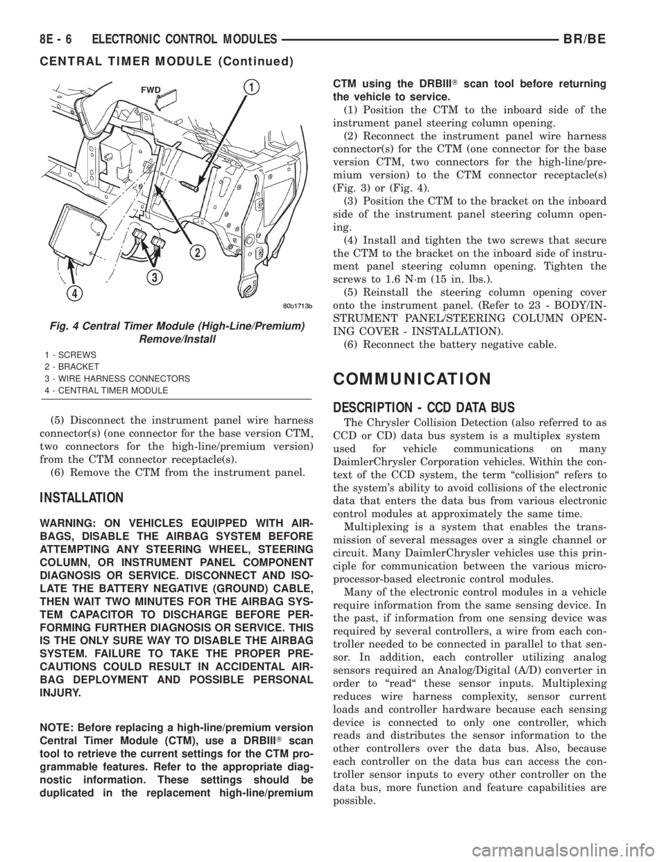
(5) Disconnect the instrument panel wire harness
connector(s) (one connector for the base version CTM,
two connectors for the high-line/premium version)
from the CTM connector receptacle(s).
(6) Remove the CTM from the instrument panel.
INSTALLATION
WARNING: ON VEHICLES EQUIPPED WITH AIR-
BAGS, DISABLE THE AIRBAG SYSTEM BEFORE
ATTEMPTING ANY STEERING WHEEL, STEERING
COLUMN, OR INSTRUMENT PANEL COMPONENT
DIAGNOSIS OR SERVICE. DISCONNECT AND ISO-
LATE THE BATTERY NEGATIVE (GROUND) CABLE,
THEN WAIT TWO MINUTES FOR THE AIRBAG SYS-
TEM CAPACITOR TO DISCHARGE BEFORE PER-
FORMING FURTHER DIAGNOSIS OR SERVICE. THIS
IS THE ONLY SURE WAY TO DISABLE THE AIRBAG
SYSTEM. FAILURE TO TAKE THE PROPER PRE-
CAUTIONS COULD RESULT IN ACCIDENTAL AIR-
BAG DEPLOYMENT AND POSSIBLE PERSONAL
INJURY.
NOTE: Before replacing a high-line/premium version
Central Timer Module (CTM), use a DRBIIITscan
tool to retrieve the current settings for the CTM pro-
grammable features. Refer to the appropriate diag-
nostic information. These settings should be
duplicated in the replacement high-line/premiumCTM using the DRBIIITscan tool before returning
the vehicle to service.
(1) Position the CTM to the inboard side of the
instrument panel steering column opening.
(2) Reconnect the instrument panel wire harness
connector(s) for the CTM (one connector for the base
version CTM, two connectors for the high-line/pre-
mium version) to the CTM connector receptacle(s)
(Fig. 3) or (Fig. 4).
(3) Position the CTM to the bracket on the inboard
side of the instrument panel steering column open-
ing.
(4) Install and tighten the two screws that secure
the CTM to the bracket on the inboard side of instru-
ment panel steering column opening. Tighten the
screws to 1.6 N´m (15 in. lbs.).
(5) Reinstall the steering column opening cover
onto the instrument panel. (Refer to 23 - BODY/IN-
STRUMENT PANEL/STEERING COLUMN OPEN-
ING COVER - INSTALLATION).
(6) Reconnect the battery negative cable.
COMMUNICATION
DESCRIPTION - CCD DATA BUS
The Chrysler Collision Detection (also referred to as
CCD or CD) data bus system is a multiplex system
used for vehicle communications on many
DaimlerChrysler Corporation vehicles. Within the con-
text of the CCD system, the term ªcollisionª refers to
the system's ability to avoid collisions of the electronic
data that enters the data bus from various electronic
control modules at approximately the same time.
Multiplexing is a system that enables the trans-
mission of several messages over a single channel or
circuit. Many DaimlerChrysler vehicles use this prin-
ciple for communication between the various micro-
processor-based electronic control modules.
Many of the electronic control modules in a vehicle
require information from the same sensing device. In
the past, if information from one sensing device was
required by several controllers, a wire from each con-
troller needed to be connected in parallel to that sen-
sor. In addition, each controller utilizing analog
sensors required an Analog/Digital (A/D) converter in
order to ªreadª these sensor inputs. Multiplexing
reduces wire harness complexity, sensor current
loads and controller hardware because each sensing
device is connected to only one controller, which
reads and distributes the sensor information to the
other controllers over the data bus. Also, because
each controller on the data bus can access the con-
troller sensor inputs to every other controller on the
data bus, more function and feature capabilities are
possible.
Fig. 4 Central Timer Module (High-Line/Premium)
Remove/Install
1 - SCREWS
2 - BRACKET
3 - WIRE HARNESS CONNECTORS
4 - CENTRAL TIMER MODULE
8E - 6 ELECTRONIC CONTROL MODULESBR/BE
CENTRAL TIMER MODULE (Continued)
Page 372 of 2255
In addition to reducing wire harness complexity,
component sensor current loads and controller hard-
ware, multiplexing offers a diagnostic advantage. A
multiplex system allows the information flowing
between controllers to be monitored using a diagnos-
tic scan tool. The DaimlerChrysler system allows an
electronic control module to broadcast message data
out onto the bus where all other electronic control
modules can ªhearº the messages that are being sent.
When a module hears a message on the data bus
that it requires, it relays that message to its micro-
processor. Each module ignores the messages on the
data bus that are being sent to other electronic con-
trol modules.
With a diagnostic scan tool connected into the CCD
circuit, a technician is able to observe many of the
electronic control module function and message out-
puts while; at the same time, controlling many of the
sensor message inputs. The CCD data bus, along
with the use of a DRBIIItdiagnostic scan tool and a
logic-based approach to test procedures, as found in
the appropriate diagnostic procedures manuals,
allows the trained automotive technician to more eas-
ily, accurately and efficiently diagnose the many com-
plex and integrated electronic functions and features
found on today's vehicles.
OPERATION - CCD DATA BUS
The CCD data bus system was designed to run at a
7812.5 baud rate (or 7812.5 bits per second). In order
to successfully transmit and receive binary messages
over the CCD data bus, the system requires the fol-
lowing:
²Bus (+) and Bus (±) Circuits
²CCD Chips in Each Electronic Control Module
²Bus Bias and Termination
²Bus Messaging
²Bus Message Coding
Following are additional details of each of the
above system requirements.
BUS (+) AND BUS (±) CIRCUITS
The two wires (sometimes referred to as the ªtwist-
ed pairº) that comprise the CCD data bus are the D1
circuit [Bus (+)], and the D2 circuit [Bus (±)]. The9D9
in D1 and D2 identify these as diagnostic circuits.
Transmission and receipt of binary messages on the
CCD data bus is accomplished by cycling the voltage
differential between the Bus (+) and Bus (±) circuits.
The two data bus wires are twisted together in
order to shield the wires from the effects of any Elec-
tro-Magnetic Interference (EMI) from switched volt-
age sources. An induced EMI voltage can be
generated in any wire by a nearby switched voltage
or switched ground circuit. By twisting the data bus
wires together, the induced voltage spike (either upor down) affects both wires equally. Since both wires
are affected equally, a voltage differential still exists
between the Bus (+) and Bus (±) circuits, and the
data bus messages can still be broadcast or received.
The correct specification for data bus wire twisting is
one turn for every 44.45 millimeters (1 ô inches) of
wire.
CCD CHIPS
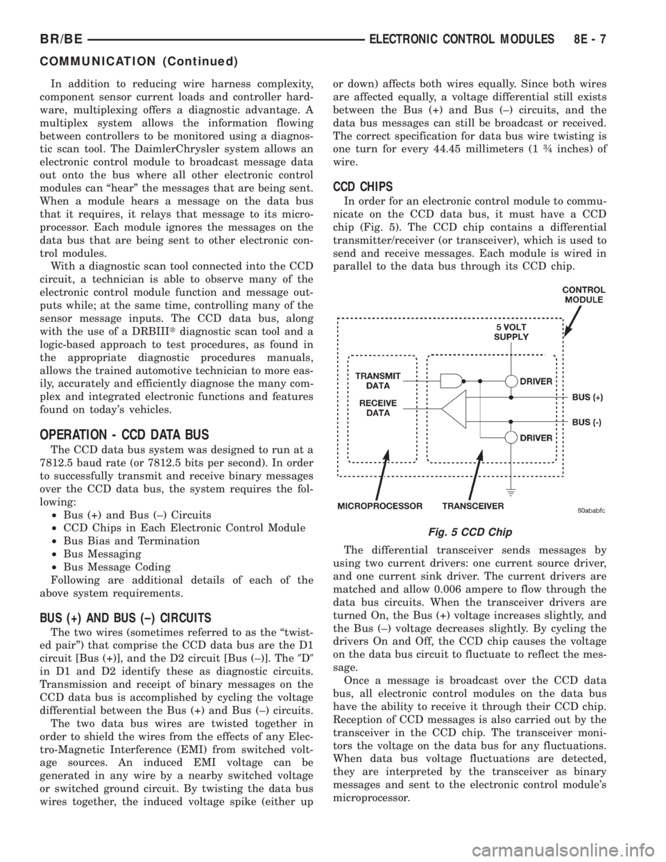
In order for an electronic control module to commu-
nicate on the CCD data bus, it must have a CCD
chip (Fig. 5). The CCD chip contains a differential
transmitter/receiver (or transceiver), which is used to
send and receive messages. Each module is wired in
parallel to the data bus through its CCD chip.
The differential transceiver sends messages by
using two current drivers: one current source driver,
and one current sink driver. The current drivers are
matched and allow 0.006 ampere to flow through the
data bus circuits. When the transceiver drivers are
turned On, the Bus (+) voltage increases slightly, and
the Bus (±) voltage decreases slightly. By cycling the
drivers On and Off, the CCD chip causes the voltage
on the data bus circuit to fluctuate to reflect the mes-
sage.
Once a message is broadcast over the CCD data
bus, all electronic control modules on the data bus
have the ability to receive it through their CCD chip.
Reception of CCD messages is also carried out by the
transceiver in the CCD chip. The transceiver moni-
tors the voltage on the data bus for any fluctuations.
When data bus voltage fluctuations are detected,
they are interpreted by the transceiver as binary
messages and sent to the electronic control module's
microprocessor.
Fig. 5 CCD Chip
BR/BEELECTRONIC CONTROL MODULES 8E - 7
COMMUNICATION (Continued)