sensor DODGE RAM 2002 Service Workshop Manual
[x] Cancel search | Manufacturer: DODGE, Model Year: 2002, Model line: RAM, Model: DODGE RAM 2002Pages: 2255, PDF Size: 62.07 MB
Page 437 of 2255
²Heated Seat Elements- Four heated seat ele-
ments are used per vehicle, one for each front seat
back and one for each front seat cushion. The ele-
ments are integral to the individual front seat and
seat back cushions and cannot be removed once
installed at the factory. Service replacement seat
heating elements are available, without having to
replace the entire seat cushion or trim cover. Refer to
the procedure in this section.
²Heated Seat Sensors- Two heated seat sen-
sors are used per vehicle, one for each front seat. The
sensors are integral to the individual front seat heat-
ing elements and cannot be removed once installed at
the factory. Service replacement seat heating ele-
ments with the sensors are available, without having
to replace the entire seat cushion or trim cover. Refer
to the procedure in this section.
²Heated Seat Relay- The heated seat relay
controls the battery voltage and current supply to the
heated seat module and the rest of the heated seat
system. The heated seat relay is mounted in the
junction block and is not different than the other
relays used throughout the vehicle. Refer to the
Power Distribution section of the service manual for
more information on standard ISO relays.
Following are general descriptions of the major
components in the heated seat system. See the own-
er's manual in the vehicle glove box for more infor-
mation on the features, use and operation of the
heated seat system. Refer toWiring Diagramsfor
the location of complete heated seat system wiring
diagrams.
OPERATION
The heated seat module receives fused battery cur-
rent through the energized heated seat relay in the
Junction Block (JB) only when the engine is running.
The heated seat switches receive battery current
through fuse #2 in the Junction Block only when the
ignition switch is in the On position. The heated seat
module shares a common ground circuit with each of
the heated seat elements. The heated seat elements
will only operate when the surface temperature of
the seat cushion is below the designed temperature
set points of the system.
The heated seat system will also be turned off
automatically whenever the ignition switch is turned
to any position except On or if the engine quits run-
ning. If the ignition switch is turned to the Off posi-
tion or if the engine quits running while a heated
seat is turned ON, the heated seat will remain Off
after the engine is restarted until a heated seat
switch is depressed again.
The heated seat module monitors inputs from the
heated seat sensors and the heated seat switches. In
response to these inputs the heated seat module usesits internal programming to control outputs to the
heated seat elements in both front seats and to con-
trol the heated seat LED indicator lamps located in
both of the heated seat switches. The heated seat
module is also programmed to provide a self-diagnos-
tic capability. When the module detects certain fail-
ures within the heated seat system, it will provide a
visual indication of the failure by flashing the indica-
tor lamps in the heated seat switches. The heated
seat module will automatically turn off the heated
seat elements if it detects a short or open in the
heated seat element circuit or a heated seat sensor
value that is out of range.
DIAGNOSIS AND TESTING - HEATED SEAT
SYSTEM
HEATED SEAT SYSTEM SELF-DIAGNOSIS
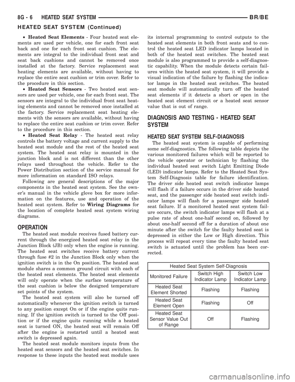
The heated seat system is capable of performing
some self-diagnostics. The following table depicts the
various monitored failures which will be reported to
the vehicle operator or technician by flashing the
individual heated seat switch Light Emitting Diode
(LED) indicator lamps. Refer to the Heated Seat Sys-
tem Self-Diagnosis table for failure identification.
The driver side heated seat switch indicator lamps
will flash if a failure occurs in the driver side heated
seat, and the passenger side heated seat switch indi-
cator lamps will flash for a passenger side heated
seat failure. If a monitored heated seat system fail-
ure occurs, the switch indicator lamps will flash at a
pulse rate of about one-half second on, followed by
about one-half second off for a duration of about one
minute after the switch for the faulty heated seat is
depressed in either the Low or High direction. This
process will repeat every time the faulty heated seat
switch is actuated until the problem has been cor-
rected.
Heated Seat System Self-Diagnosis
Monitored FailureSwitch High
Indicator LampSwitch Low
Indicator Lamp
Heated Seat
Element ShortedFlashing Flashing
Heated Seat
Element OpenFlashing Off
Heated Seat
Sensor Value Out
of RangeOff Flashing
8G - 6 HEATED SEAT SYSTEMBR/BE
HEATED SEAT SYSTEM (Continued)
Page 442 of 2255
One temperature sensor is used for each outboard
seating position of the front seat, and it is located in
the center insert area of the seat cushion cover. The
heated seat sensors and their pigtail wires are also
captured between a covering and the adhesive foam
rubber backing. The heated seat sensors are Nega-
tive Thermal Coefficient (NTC) thermistors. The sen-
sors for both front seats receive a voltage feed from a
single output of the heated seat module, but the mod-
ule receives individual sensor inputs from the driver
side and passenger side sensors.
The heated seat elements and sensors should not
be repaired. If damaged or faulty, the heated seat ele-
ment assembly must be replaced. (Refer to 8 - ELEC-
TRICAL/HEATED SEATS/HEATED SEAT
ELEMENT - REMOVAL).
OPERATION
One end of the heated seat element resistor wire is
connected to a ground feed at all times through a
splice in the heated seat module ground circuit. Bat-
tery current is directed to the other end of the heated
seat element resistor wire by the energized N-chan-
nel Field Effect Transistor (N-FET) located within
the heated seat module. The heated seat module will
energize the N-FET only when the heated seat
switch is in the Low or High position and the heated
seat sensor indicates that the seat cushion surface
temperature is below the selected (Low or High) tem-
perature set point. As electrical current passes
through the heating element grid, the resistance of
the wire used in the element disperses some of that
electrical current in the form of heat. The heat pro-
duced by the heated seat element grid then radiates
through the underside of the seat cushion and seat
back trim covers, warming the seat cover and its
occupant.
The resistance of the heated seat sensor increases
and decreases as the surface temperature of the seat
cushion cover changes. The heated seat module sup-
plies each sensor with a voltage feed, then detects
the sensor resistance by monitoring the voltage of the
separate sensor return circuits. The heated seat mod-
ule compares the heated seat sensor resistance (seat
cushion surface temperature) with the heated seat
switch resistance (Low or High set point) to deter-
mine when the heated seat element grids need to be
cycled on or off in order to maintain the selected tem-
perature set point.
DIAGNOSIS AND TESTING - HEATED SEAT
ELEMENT AND SENSOR
The heated seat module will self-diagnose shorted
or open heated seat element circuits and sensor cir-
cuits. Refer to Heated Seat System Diagnosis and
Testing in this section for additional diagnosis and
testing procedures. To manually check the heated
seat element and sensor circuits, proceed as follows.
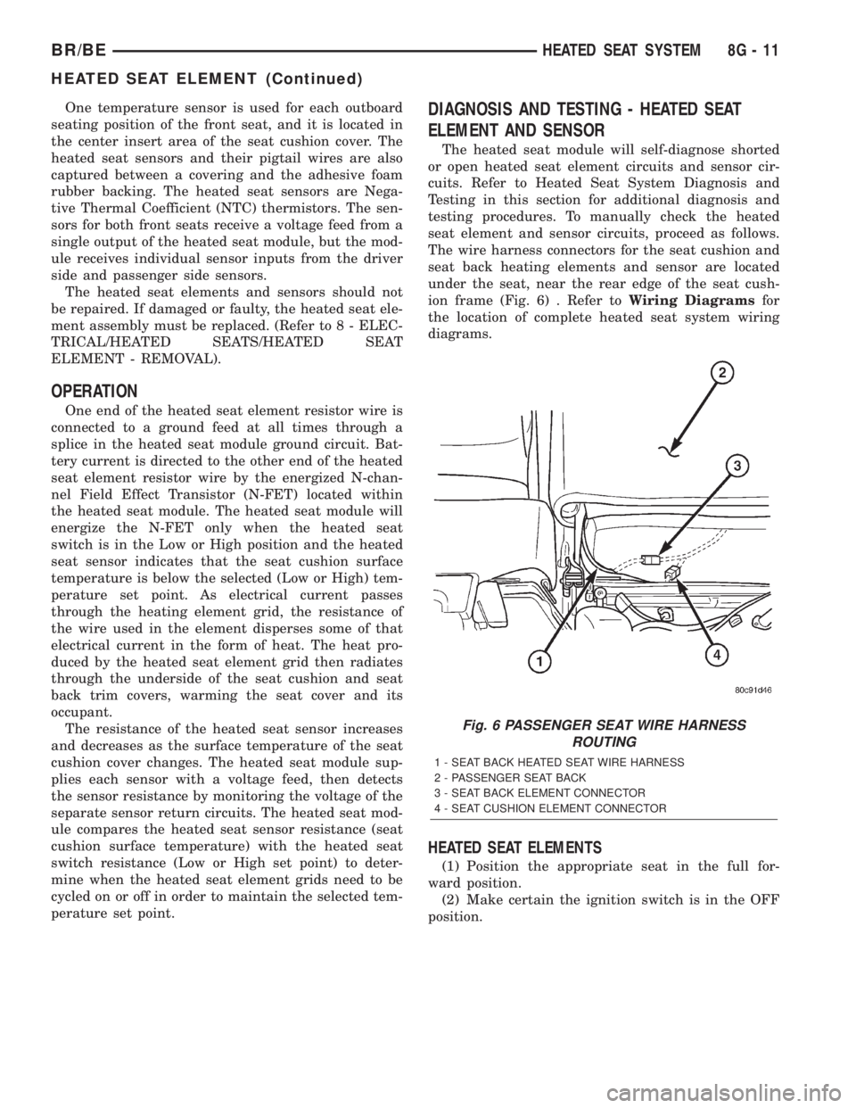
The wire harness connectors for the seat cushion and
seat back heating elements and sensor are located
under the seat, near the rear edge of the seat cush-
ion frame (Fig. 6) . Refer toWiring Diagramsfor
the location of complete heated seat system wiring
diagrams.
HEATED SEAT ELEMENTS
(1) Position the appropriate seat in the full for-
ward position.
(2) Make certain the ignition switch is in the OFF
position.
Fig. 6 PASSENGER SEAT WIRE HARNESS
ROUTING
1 - SEAT BACK HEATED SEAT WIRE HARNESS
2 - PASSENGER SEAT BACK
3 - SEAT BACK ELEMENT CONNECTOR
4 - SEAT CUSHION ELEMENT CONNECTOR
BR/BEHEATED SEAT SYSTEM 8G - 11
HEATED SEAT ELEMENT (Continued)
Page 443 of 2255
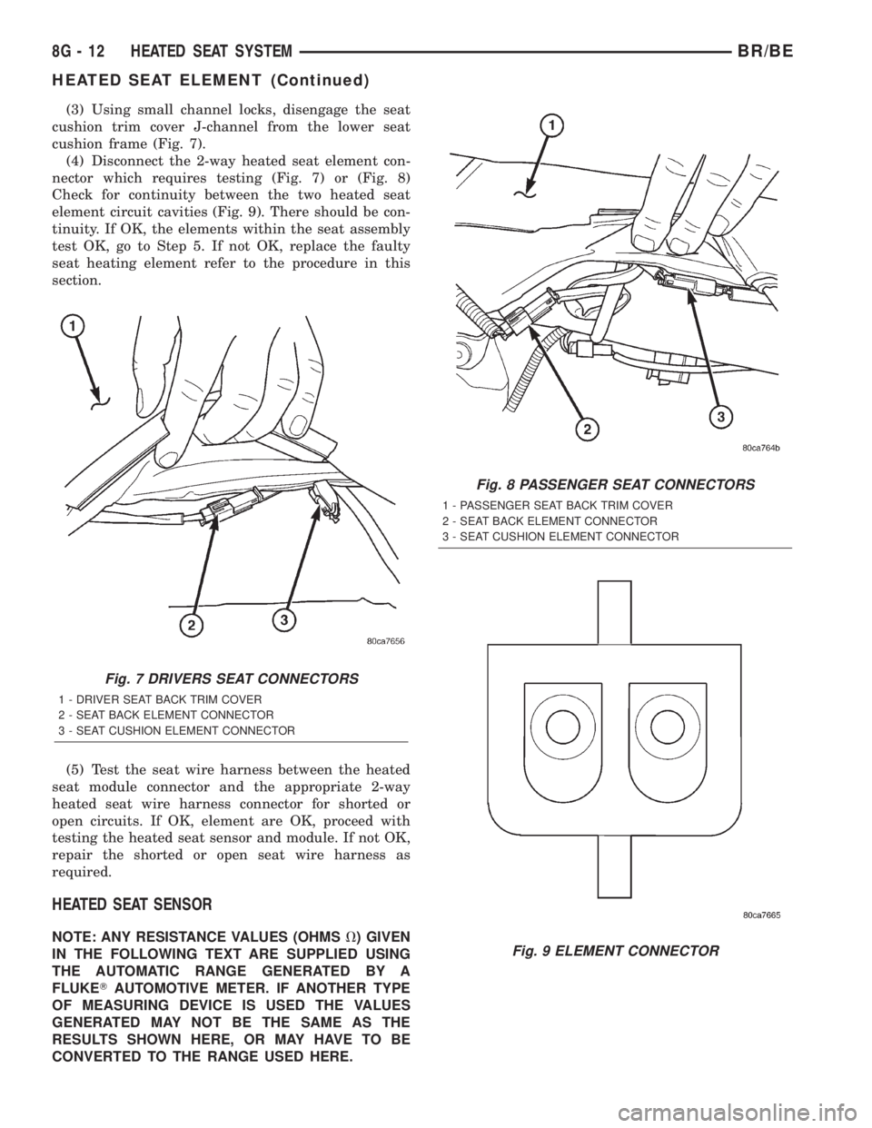
(3) Using small channel locks, disengage the seat
cushion trim cover J-channel from the lower seat
cushion frame (Fig. 7).
(4) Disconnect the 2-way heated seat element con-
nector which requires testing (Fig. 7) or (Fig. 8)
Check for continuity between the two heated seat
element circuit cavities (Fig. 9). There should be con-
tinuity. If OK, the elements within the seat assembly
test OK, go to Step 5. If not OK, replace the faulty
seat heating element refer to the procedure in this
section.
(5) Test the seat wire harness between the heated
seat module connector and the appropriate 2-way
heated seat wire harness connector for shorted or
open circuits. If OK, element are OK, proceed with
testing the heated seat sensor and module. If not OK,
repair the shorted or open seat wire harness as
required.
HEATED SEAT SENSOR
NOTE: ANY RESISTANCE VALUES (OHMSV) GIVEN
IN THE FOLLOWING TEXT ARE SUPPLIED USING
THE AUTOMATIC RANGE GENERATED BY A
FLUKETAUTOMOTIVE METER. IF ANOTHER TYPE
OF MEASURING DEVICE IS USED THE VALUES
GENERATED MAY NOT BE THE SAME AS THE
RESULTS SHOWN HERE, OR MAY HAVE TO BE
CONVERTED TO THE RANGE USED HERE.
Fig. 7 DRIVERS SEAT CONNECTORS
1 - DRIVER SEAT BACK TRIM COVER
2 - SEAT BACK ELEMENT CONNECTOR
3 - SEAT CUSHION ELEMENT CONNECTOR
Fig. 8 PASSENGER SEAT CONNECTORS
1 - PASSENGER SEAT BACK TRIM COVER
2 - SEAT BACK ELEMENT CONNECTOR
3 - SEAT CUSHION ELEMENT CONNECTOR
Fig. 9 ELEMENT CONNECTOR
8G - 12 HEATED SEAT SYSTEMBR/BE
HEATED SEAT ELEMENT (Continued)
Page 444 of 2255
(1) Position the appropriate seat in the full for-
ward position.
(2) Make certain the ignition switch is in the OFF
position.
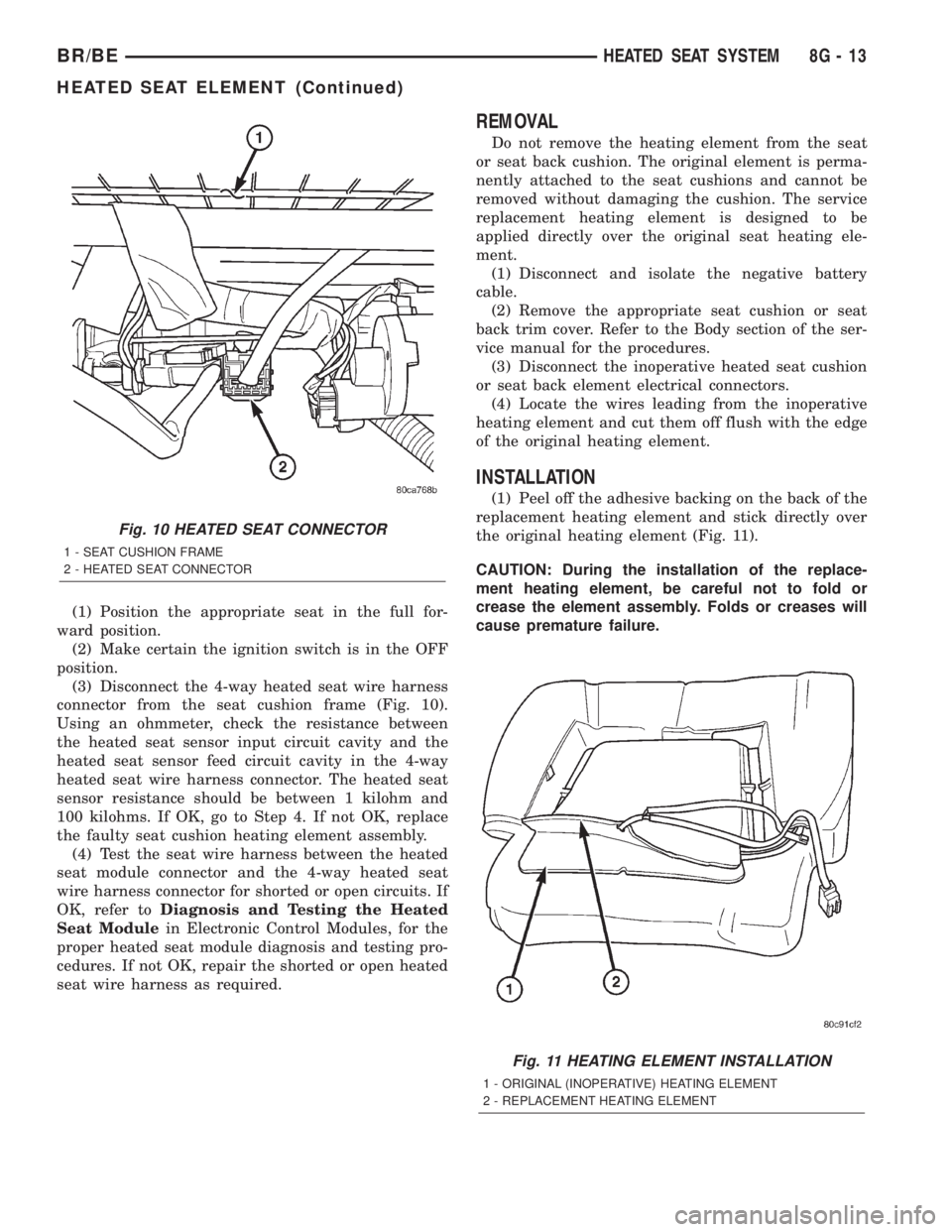
(3) Disconnect the 4-way heated seat wire harness
connector from the seat cushion frame (Fig. 10).
Using an ohmmeter, check the resistance between
the heated seat sensor input circuit cavity and the
heated seat sensor feed circuit cavity in the 4-way
heated seat wire harness connector. The heated seat
sensor resistance should be between 1 kilohm and
100 kilohms. If OK, go to Step 4. If not OK, replace
the faulty seat cushion heating element assembly.
(4) Test the seat wire harness between the heated
seat module connector and the 4-way heated seat
wire harness connector for shorted or open circuits. If
OK, refer toDiagnosis and Testing the Heated
Seat Modulein Electronic Control Modules, for the
proper heated seat module diagnosis and testing pro-
cedures. If not OK, repair the shorted or open heated
seat wire harness as required.
REMOVAL
Do not remove the heating element from the seat
or seat back cushion. The original element is perma-
nently attached to the seat cushions and cannot be
removed without damaging the cushion. The service
replacement heating element is designed to be
applied directly over the original seat heating ele-
ment.
(1) Disconnect and isolate the negative battery
cable.
(2) Remove the appropriate seat cushion or seat
back trim cover. Refer to the Body section of the ser-
vice manual for the procedures.
(3) Disconnect the inoperative heated seat cushion
or seat back element electrical connectors.
(4) Locate the wires leading from the inoperative
heating element and cut them off flush with the edge
of the original heating element.
INSTALLATION
(1) Peel off the adhesive backing on the back of the
replacement heating element and stick directly over
the original heating element (Fig. 11).
CAUTION: During the installation of the replace-
ment heating element, be careful not to fold or
crease the element assembly. Folds or creases will
cause premature failure.
Fig. 10 HEATED SEAT CONNECTOR
1 - SEAT CUSHION FRAME
2 - HEATED SEAT CONNECTOR
Fig. 11 HEATING ELEMENT INSTALLATION
1 - ORIGINAL (INOPERATIVE) HEATING ELEMENT
2 - REPLACEMENT HEATING ELEMENT
BR/BEHEATED SEAT SYSTEM 8G - 13
HEATED SEAT ELEMENT (Continued)
Page 458 of 2255
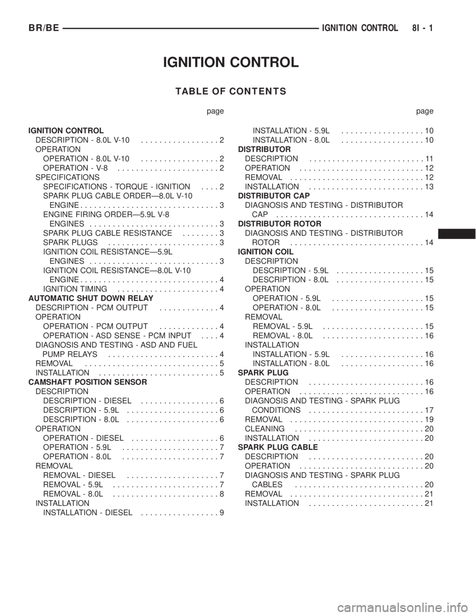
IGNITION CONTROL
TABLE OF CONTENTS
page page
IGNITION CONTROL
DESCRIPTION - 8.0L V-10.................2
OPERATION
OPERATION - 8.0L V-10.................2
OPERATION - V-8......................2
SPECIFICATIONS
SPECIFICATIONS - TORQUE - IGNITION....2
SPARK PLUG CABLE ORDERÐ8.0L V-10
ENGINE..............................3
ENGINE FIRING ORDERÐ5.9L V-8
ENGINES............................3
SPARK PLUG CABLE RESISTANCE........3
SPARK PLUGS........................3
IGNITION COIL RESISTANCEÐ5.9L
ENGINES............................3
IGNITION COIL RESISTANCEÐ8.0L V-10
ENGINE..............................4
IGNITION TIMING......................4
AUTOMATIC SHUT DOWN RELAY
DESCRIPTION - PCM OUTPUT.............4
OPERATION
OPERATION - PCM OUTPUT.............4
OPERATION - ASD SENSE - PCM INPUT....4
DIAGNOSIS AND TESTING - ASD AND FUEL
PUMP RELAYS........................4
REMOVAL.............................5
INSTALLATION..........................5
CAMSHAFT POSITION SENSOR
DESCRIPTION
DESCRIPTION - DIESEL.................6
DESCRIPTION - 5.9L....................6
DESCRIPTION - 8.0L....................6
OPERATION
OPERATION - DIESEL...................6
OPERATION - 5.9L.....................7
OPERATION - 8.0L.....................7
REMOVAL
REMOVAL - DIESEL....................7
REMOVAL - 5.9L.......................7
REMOVAL - 8.0L.......................8
INSTALLATION
INSTALLATION - DIESEL.................9INSTALLATION - 5.9L..................10
INSTALLATION - 8.0L..................10
DISTRIBUTOR
DESCRIPTION.........................11
OPERATION...........................12
REMOVAL.............................12
INSTALLATION.........................13
DISTRIBUTOR CAP
DIAGNOSIS AND TESTING - DISTRIBUTOR
CAP ................................14
DISTRIBUTOR ROTOR
DIAGNOSIS AND TESTING - DISTRIBUTOR
ROTOR .............................14
IGNITION COIL
DESCRIPTION
DESCRIPTION - 5.9L...................15
DESCRIPTION - 8.0L...................15
OPERATION
OPERATION - 5.9L....................15
OPERATION - 8.0L....................15
REMOVAL
REMOVAL - 5.9L......................15
REMOVAL - 8.0L......................16
INSTALLATION
INSTALLATION - 5.9L..................16
INSTALLATION - 8.0L..................16
SPARK PLUG
DESCRIPTION.........................16
OPERATION...........................16
DIAGNOSIS AND TESTING - SPARK PLUG
CONDITIONS.........................17
REMOVAL.............................19
CLEANING............................20
INSTALLATION.........................20
SPARK PLUG CABLE
DESCRIPTION.........................20
OPERATION...........................20
DIAGNOSIS AND TESTING - SPARK PLUG
CABLES............................20
REMOVAL.............................21
INSTALLATION.........................21
BR/BEIGNITION CONTROL 8I - 1
Page 459 of 2255
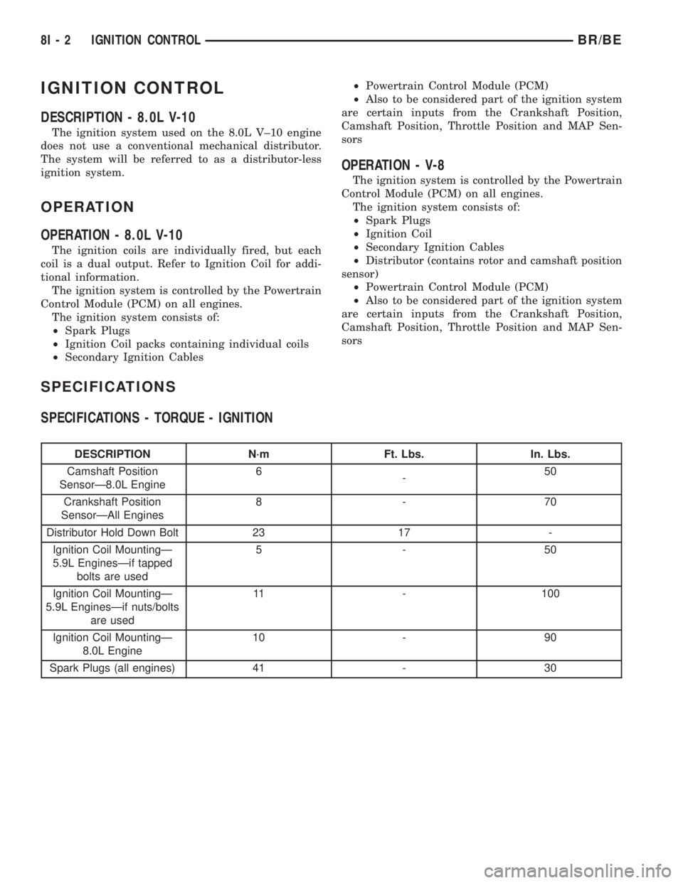
IGNITION CONTROL
DESCRIPTION - 8.0L V-10
The ignition system used on the 8.0L V±10 engine
does not use a conventional mechanical distributor.
The system will be referred to as a distributor-less
ignition system.
OPERATION
OPERATION - 8.0L V-10
The ignition coils are individually fired, but each
coil is a dual output. Refer to Ignition Coil for addi-
tional information.
The ignition system is controlled by the Powertrain
Control Module (PCM) on all engines.
The ignition system consists of:
²Spark Plugs
²Ignition Coil packs containing individual coils
²Secondary Ignition Cables²Powertrain Control Module (PCM)
²Also to be considered part of the ignition system
are certain inputs from the Crankshaft Position,
Camshaft Position, Throttle Position and MAP Sen-
sors
OPERATION - V-8
The ignition system is controlled by the Powertrain
Control Module (PCM) on all engines.
The ignition system consists of:
²Spark Plugs
²Ignition Coil
²Secondary Ignition Cables
²Distributor (contains rotor and camshaft position
sensor)
²Powertrain Control Module (PCM)
²Also to be considered part of the ignition system
are certain inputs from the Crankshaft Position,
Camshaft Position, Throttle Position and MAP Sen-
sors
SPECIFICATIONS
SPECIFICATIONS - TORQUE - IGNITION
DESCRIPTION N´m Ft. Lbs. In. Lbs.
Camshaft Position
SensorÐ8.0L Engine6
-50
Crankshaft Position
SensorÐAll Engines8-70
Distributor Hold Down Bolt 23 17 -
Ignition Coil MountingÐ
5.9L EnginesÐif tapped
bolts are used5-50
Ignition Coil MountingÐ
5.9L EnginesÐif nuts/bolts
are used11 - 100
Ignition Coil MountingÐ
8.0L Engine10 - 90
Spark Plugs (all engines) 41 - 30
8I - 2 IGNITION CONTROLBR/BE
Page 461 of 2255
IGNITION COIL RESISTANCEÐ8.0L V-10
ENGINE
Primary Resistance: 0.53-0.65 Ohms. Test across the
primary connector. Refer to text for test procedures.
Secondary Resistance: 10.9-14.7K Ohms. Test
across the individual coil towers. Refer to text for test
procedures.
IGNITION TIMING
Ignition timing is not adjustable on any engine.
AUTOMATIC SHUT DOWN
RELAY
DESCRIPTION - PCM OUTPUT
The 5±pin, 12±volt, Automatic Shutdown (ASD)
relay is located in the Power Distribution Center
(PDC). Refer to label on PDC cover for relay location.
OPERATION
OPERATION - PCM OUTPUT
The ASD relay supplies battery voltage (12+ volts)
to the fuel injectors and ignition coil(s). With certain
emissions packages it also supplies 12±volts to the
oxygen sensor heating elements.
The ground circuit for the coil within the ASD
relay is controlled by the Powertrain Control Module
(PCM). The PCM operates the ASD relay by switch-
ing its ground circuit on and off.
The ASD relay will be shut±down, meaning the
12±volt power supply to the ASD relay will be de-ac-
tivated by the PCM if:
²the ignition key is left in the ON position. This
is if the engine has not been running for approxi-
mately 1.8 seconds.
²there is a crankshaft position sensor signal to
the PCM that is lower than pre-determined values.
OPERATION - ASD SENSE - PCM INPUT
A 12 volt signal at this input indicates to the PCM
that the ASD has been activated. The relay is used to
connect the oxygen sensor heater element, ignition
coil and fuel injectors to 12 volt + power supply.
This input is used only to sense that the ASD relay
is energized. If the Powertrain Control Module
(PCM) does not see 12 volts at this input when the
ASD should be activated, it will set a Diagnostic
Trouble Code (DTC).
DIAGNOSIS AND TESTING - ASD AND FUEL
PUMP RELAYS
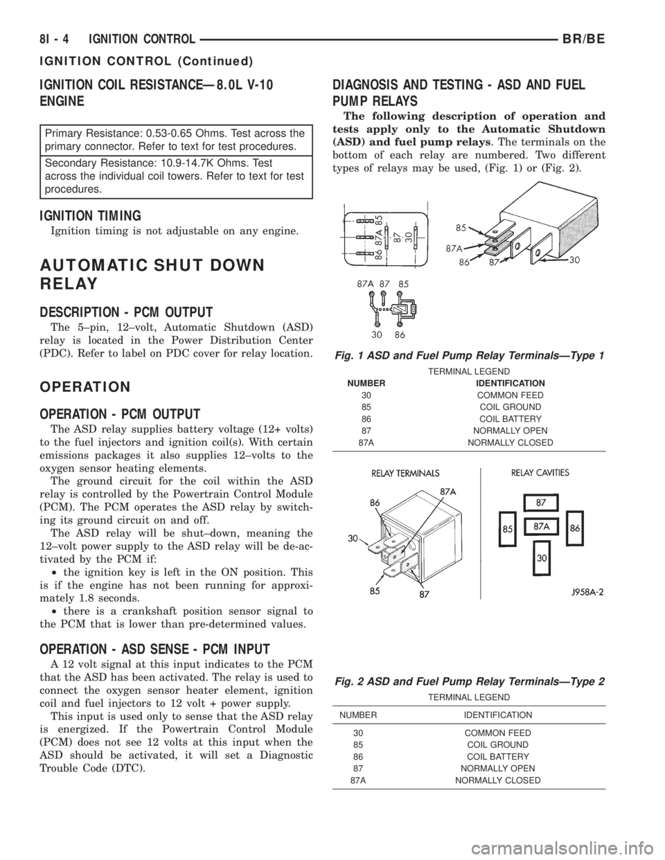
The following description of operation and
tests apply only to the Automatic Shutdown
(ASD) and fuel pump relays. The terminals on the
bottom of each relay are numbered. Two different
types of relays may be used, (Fig. 1) or (Fig. 2).
Fig. 1 ASD and Fuel Pump Relay TerminalsÐType 1
TERMINAL LEGEND
NUMBER IDENTIFICATION
30 COMMON FEED
85 COIL GROUND
86 COIL BATTERY
87 NORMALLY OPEN
87A NORMALLY CLOSED
Fig. 2 ASD and Fuel Pump Relay TerminalsÐType 2
TERMINAL LEGEND
NUMBER IDENTIFICATION
30 COMMON FEED
85 COIL GROUND
86 COIL BATTERY
87 NORMALLY OPEN
87A NORMALLY CLOSED
8I - 4 IGNITION CONTROLBR/BE
IGNITION CONTROL (Continued)
Page 463 of 2255
CAMSHAFT POSITION
SENSOR
DESCRIPTION
DESCRIPTION - DIESEL
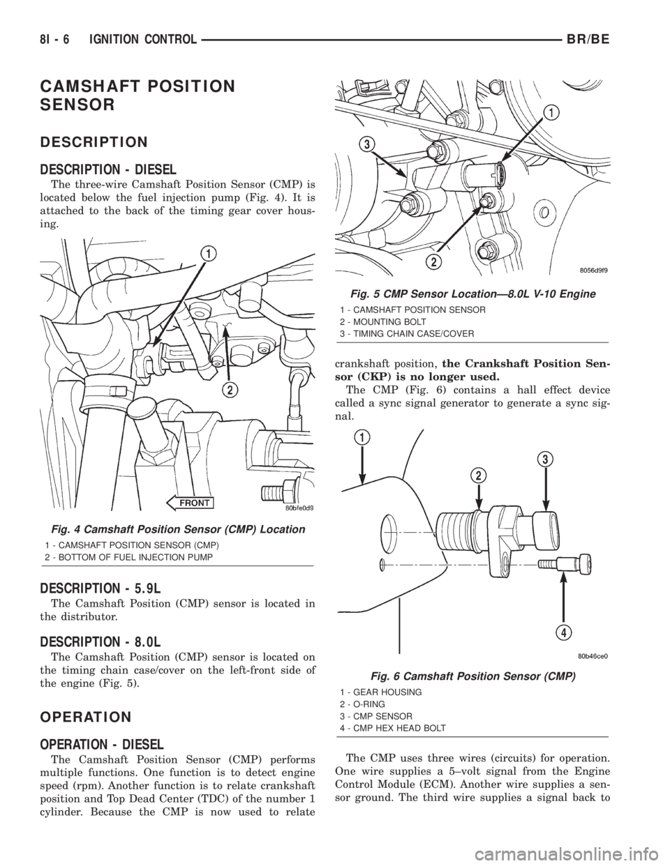
The three-wire Camshaft Position Sensor (CMP) is
located below the fuel injection pump (Fig. 4). It is
attached to the back of the timing gear cover hous-
ing.
DESCRIPTION - 5.9L
The Camshaft Position (CMP) sensor is located in
the distributor.
DESCRIPTION - 8.0L
The Camshaft Position (CMP) sensor is located on
the timing chain case/cover on the left-front side of
the engine (Fig. 5).
OPERATION
OPERATION - DIESEL
The Camshaft Position Sensor (CMP) performs
multiple functions. One function is to detect engine
speed (rpm). Another function is to relate crankshaft
position and Top Dead Center (TDC) of the number 1
cylinder. Because the CMP is now used to relatecrankshaft position,the Crankshaft Position Sen-
sor (CKP) is no longer used.
The CMP (Fig. 6) contains a hall effect device
called a sync signal generator to generate a sync sig-
nal.
The CMP uses three wires (circuits) for operation.
One wire supplies a 5±volt signal from the Engine
Control Module (ECM). Another wire supplies a sen-
sor ground. The third wire supplies a signal back to
Fig. 4 Camshaft Position Sensor (CMP) Location
1 - CAMSHAFT POSITION SENSOR (CMP)
2 - BOTTOM OF FUEL INJECTION PUMP
Fig. 5 CMP Sensor LocationÐ8.0L V-10 Engine
1 - CAMSHAFT POSITION SENSOR
2 - MOUNTING BOLT
3 - TIMING CHAIN CASE/COVER
Fig. 6 Camshaft Position Sensor (CMP)
1 - GEAR HOUSING
2 - O-RING
3 - CMP SENSOR
4 - CMP HEX HEAD BOLT
8I - 6 IGNITION CONTROLBR/BE
Page 464 of 2255
the ECM relating engine speed and crankshaft posi-
tion.
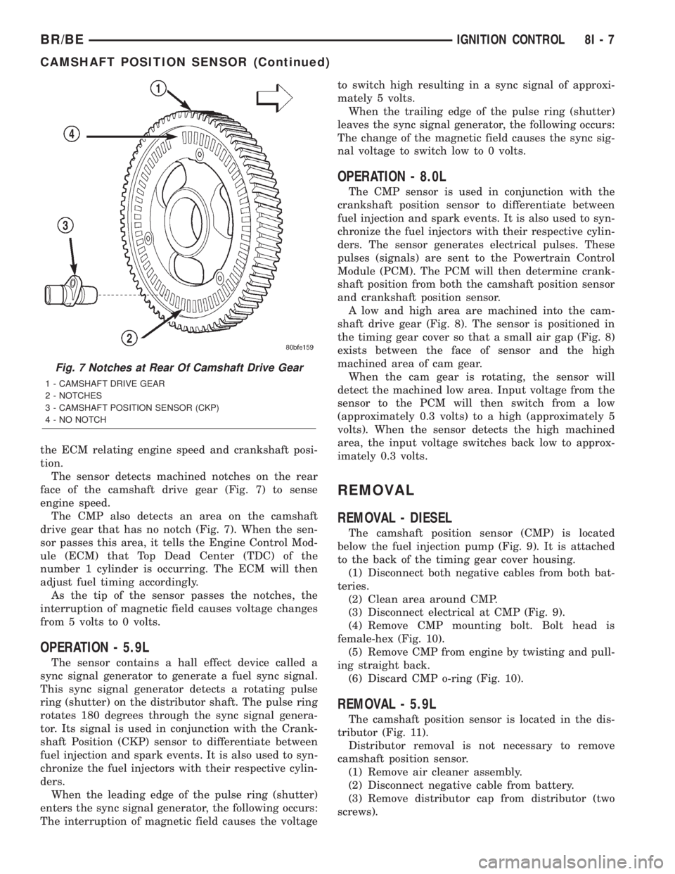
The sensor detects machined notches on the rear
face of the camshaft drive gear (Fig. 7) to sense
engine speed.
The CMP also detects an area on the camshaft
drive gear that has no notch (Fig. 7). When the sen-
sor passes this area, it tells the Engine Control Mod-
ule (ECM) that Top Dead Center (TDC) of the
number 1 cylinder is occurring. The ECM will then
adjust fuel timing accordingly.
As the tip of the sensor passes the notches, the
interruption of magnetic field causes voltage changes
from 5 volts to 0 volts.
OPERATION - 5.9L
The sensor contains a hall effect device called a
sync signal generator to generate a fuel sync signal.
This sync signal generator detects a rotating pulse
ring (shutter) on the distributor shaft. The pulse ring
rotates 180 degrees through the sync signal genera-
tor. Its signal is used in conjunction with the Crank-
shaft Position (CKP) sensor to differentiate between
fuel injection and spark events. It is also used to syn-
chronize the fuel injectors with their respective cylin-
ders.
When the leading edge of the pulse ring (shutter)
enters the sync signal generator, the following occurs:
The interruption of magnetic field causes the voltageto switch high resulting in a sync signal of approxi-
mately 5 volts.
When the trailing edge of the pulse ring (shutter)
leaves the sync signal generator, the following occurs:
The change of the magnetic field causes the sync sig-
nal voltage to switch low to 0 volts.
OPERATION - 8.0L
The CMP sensor is used in conjunction with the
crankshaft position sensor to differentiate between
fuel injection and spark events. It is also used to syn-
chronize the fuel injectors with their respective cylin-
ders. The sensor generates electrical pulses. These
pulses (signals) are sent to the Powertrain Control
Module (PCM). The PCM will then determine crank-
shaft position from both the camshaft position sensor
and crankshaft position sensor.
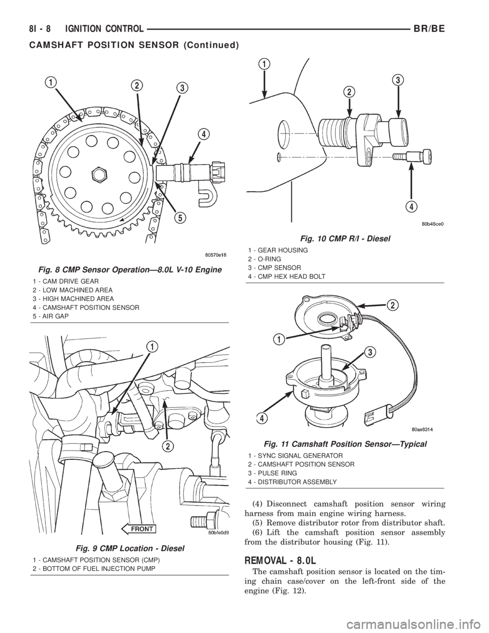
A low and high area are machined into the cam-
shaft drive gear (Fig. 8). The sensor is positioned in
the timing gear cover so that a small air gap (Fig. 8)
exists between the face of sensor and the high
machined area of cam gear.
When the cam gear is rotating, the sensor will
detect the machined low area. Input voltage from the
sensor to the PCM will then switch from a low
(approximately 0.3 volts) to a high (approximately 5
volts). When the sensor detects the high machined
area, the input voltage switches back low to approx-
imately 0.3 volts.
REMOVAL
REMOVAL - DIESEL
The camshaft position sensor (CMP) is located
below the fuel injection pump (Fig. 9). It is attached
to the back of the timing gear cover housing.
(1) Disconnect both negative cables from both bat-
teries.
(2) Clean area around CMP.
(3) Disconnect electrical at CMP (Fig. 9).
(4) Remove CMP mounting bolt. Bolt head is
female-hex (Fig. 10).
(5) Remove CMP from engine by twisting and pull-
ing straight back.
(6) Discard CMP o-ring (Fig. 10).
REMOVAL - 5.9L
The camshaft position sensor is located in the dis-
tributor (Fig. 11).
Distributor removal is not necessary to remove
camshaft position sensor.
(1) Remove air cleaner assembly.
(2) Disconnect negative cable from battery.
(3) Remove distributor cap from distributor (two
screws).
Fig. 7 Notches at Rear Of Camshaft Drive Gear
1 - CAMSHAFT DRIVE GEAR
2 - NOTCHES
3 - CAMSHAFT POSITION SENSOR (CKP)
4 - NO NOTCH
BR/BEIGNITION CONTROL 8I - 7
CAMSHAFT POSITION SENSOR (Continued)
Page 465 of 2255
(4) Disconnect camshaft position sensor wiring
harness from main engine wiring harness.
(5) Remove distributor rotor from distributor shaft.
(6) Lift the camshaft position sensor assembly
from the distributor housing (Fig. 11).
REMOVAL - 8.0L
The camshaft position sensor is located on the tim-
ing chain case/cover on the left-front side of the
engine (Fig. 12).
Fig. 8 CMP Sensor OperationÐ8.0L V-10 Engine
1 - CAM DRIVE GEAR
2 - LOW MACHINED AREA
3 - HIGH MACHINED AREA
4 - CAMSHAFT POSITION SENSOR
5 - AIR GAP
Fig. 9 CMP Location - Diesel
1 - CAMSHAFT POSITION SENSOR (CMP)
2 - BOTTOM OF FUEL INJECTION PUMP
Fig. 10 CMP R/I - Diesel
1 - GEAR HOUSING
2 - O-RING
3 - CMP SENSOR
4 - CMP HEX HEAD BOLT
Fig. 11 Camshaft Position SensorÐTypical
1 - SYNC SIGNAL GENERATOR
2 - CAMSHAFT POSITION SENSOR
3 - PULSE RING
4 - DISTRIBUTOR ASSEMBLY
8I - 8 IGNITION CONTROLBR/BE
CAMSHAFT POSITION SENSOR (Continued)