window switch DODGE RAM 2002 Service Owner's Manual
[x] Cancel search | Manufacturer: DODGE, Model Year: 2002, Model line: RAM, Model: DODGE RAM 2002Pages: 2255, PDF Size: 62.07 MB
Page 938 of 2255

Component Page
Left Rear Fender Lamp
(Dual Rear Wheels)................ 8W-80-59
Left Rear Speaker (Premium 2 Door).... 8W-80-59
Left Rear Speaker (Premium 4 Door).... 8W-80-60
Left Rear Speaker (Standard 2 Door).... 8W-80-60
Left Rear Speaker (Standard 4 Door).... 8W-80-60
Left Remote Radio Switch............. 8W-80-60
Left Speed Control Switch............ 8W-80-60
Left Tail/Stop/Turn Signal Lamp........ 8W-80-61
Left Tweeter (Premium).............. 8W-80-61
Left Visor/Vanity Lamp............... 8W-80-61
Low Note Horn..................... 8W-80-61
Manifold Absolute Pressure Sensor
(3.9L/5.2L/5.9L)................... 8W-80-61
Manifold Absolute Pressure Sensor
(8.0L).......................... 8W-80-62
Manifold Air Pressure Sensor (Diesel).... 8W-80-62
Multi-Function Switch............... 8W-80-62
Output Speed Sensor................ 8W-80-63
Overdrive Switch................... 8W-80-63
Overhead Console (Base).............. 8W-80-63
Overhead Console (Highline)........... 8W-80-63
Oxygen Sensor 1/1 Left Bank Up
(5.9L HD/8.0L)................... 8W-80-63
Oxygen Sensor 1/1 Left Bank Up
(California)...................... 8W-80-64
Oxygen Sensor 1/1 Upstream
(A/T Except 8.0L)................. 8W-80-64
Oxygen Sensor 1/1 Upstream
(M/T Except 8.0L)................. 8W-80-64
Oxygen Sensor 1/2 Downstream
(3.9L/5.2L)....................... 8W-80-64
Oxygen Sensor 1/2 Left Bank Down
(California)...................... 8W-80-64
Oxygen Sensor 1/2 Pre-Catalyst (8.0L) . . . 8W-80-65
Oxygen Sensor 1/3 Post Catalyst (8.0L) . . 8W-80-65
Oxygen Sensor 2/1 Right Bank Up (5.9l HD)
(5.2L/5.9L/8.0L California).......... 8W-80-65
Oxygen Sensor 2/2 Right Bank Down
(California)...................... 8W-80-65
Park/Neutral Position Switch (A/T)...... 8W-80-65
Passenger Airbag................... 8W-80-66
Passenger Airbag On/Off Switch C1..... 8W-80-66
Passenger Airbag On/Off Switch C2..... 8W-80-66
Passenger Cylinder Lock Switch........ 8W-80-66
Passenger Door Ajar Switch........... 8W-80-66
Passenger Door Lock Motor........... 8W-80-66
Passenger Door Window/Lock Switch.... 8W-80-67
Passenger Heated Seat Cushion........ 8W-80-67
Passenger Heated Seat Switch......... 8W-80-67
Passenger Lumbar Motor............. 8W-80-67
Passenger Power Seat Front Vertical Motor
(Club Cab)....................... 8W-80-68
Passenger Power Seat Horizontal Motor
(Club Cab)....................... 8W-80-68Component Page
Passenger Power Seat Rear Vertical Motor
(Club Cab)....................... 8W-80-68
Passenger Power Seat Switch (Club Cab) . 8W-80-68
Passenger Power Window Motor........ 8W-80-68
Power Mirror Switch................. 8W-80-69
Power Outlet....................... 8W-80-69
Powertrain Control Module C1 (Diesel) . . . 8W-80-69
Powertrain Control Module C1 (Gas).... 8W-80-70
Powertrain Control Module C2 (Diesel) . . . 8W-80-71
Powertrain Control Module C2 (Gas).... 8W-80-71
Powertrain Control Module C3 (Diesel) . . . 8W-80-72
Powertrain Control Module C3 (Gas).... 8W-80-73
Radio C1.......................... 8W-80-74
Radio C2.......................... 8W-80-74
Radio C3.......................... 8W-80-74
Radio Choke Relay.................. 8W-80-74
Rear Wheel Speed Sensor (ABS)........ 8W-80-74
Right Back-Up Lamp................ 8W-80-75
Right Fog Lamp.................... 8W-80-75
Right Front Door Speaker (Premium).... 8W-80-75
Right Front Door Speaker (Standard).... 8W-80-75
Right Front Fender Lamp
(Dual Rear Wheels)................ 8W-80-75
Right Front Wheel Speed Sensor (ABS) . . 8W-80-76
Right Headlamp.................... 8W-80-76
Right License Lamp................. 8W-80-76
Right Outboard Clearance Lamp....... 8W-80-76
Right Outboard Headlamp............ 8W-80-76
Right Outboard Identification Lamp..... 8W-80-77
Right Park/Turn Signal Lamp.......... 8W-80-77
Right Power Mirror.................. 8W-80-77
Right Rear Fender Lamp
(Dual Rear Wheels)................ 8W-80-77
Right Rear Speaker (2 Door Premium) . . . 8W-80-77
Right Rear Speaker (4 Door Premium) . . . 8W-80-78
Right Rear Speaker (Standard 2 Door) . . . 8W-80-78
Right Rear Speaker (Standard 4 Door) . . . 8W-80-78
Right Remote Radio Switch........... 8W-80-78
Right Speed Control Switch........... 8W-80-78
Right Tail/Stop/Turn Signal Lamp...... 8W-80-78
Right Tweeter (Premium)............. 8W-80-79
Right Visor/Vanity Lamp.............. 8W-80-79
Seat Belt Switch (Club Cab)........... 8W-80-79
Seat Belt Switch (Standard Cab)....... 8W-80-79
Seat Heat Interface Module........... 8W-80-79
Speed Control Servo................. 8W-80-80
Tailgate Lamp (Dual Rear Wheels)...... 8W-80-80
Throttle Position Sensor (Gas)......... 8W-80-80
Trailer Tow Connector................ 8W-80-80
Transmission Solenoid Assembly........ 8W-80-80
Underhood Lamp................... 8W-80-81
Washer Fluid Level Switch............ 8W-80-81
Water In Fuel Sensor (Diesel).......... 8W-80-81
Wiper Motor....................... 8W-80-81
BR/BE8W-80 CONNECTOR PIN-OUTS 8W - 80 - 3
Page 973 of 2255
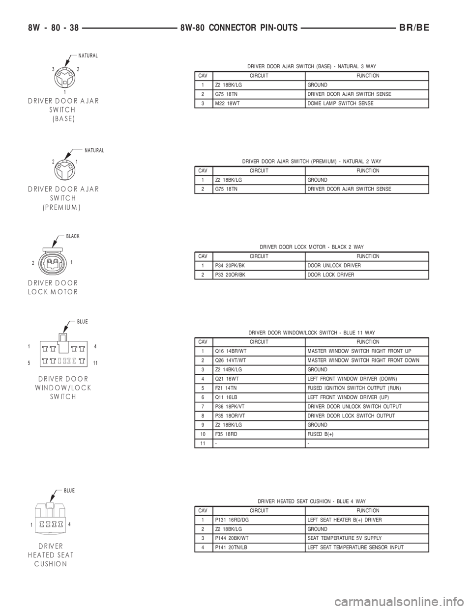
DRIVER DOOR AJAR SWITCH (BASE) - NATURAL 3 WAY
CAV CIRCUIT FUNCTION
1 Z2 18BK/LG GROUND
2 G75 18TN DRIVER DOOR AJAR SWITCH SENSE
3 M22 18WT DOME LAMP SWITCH SENSE
DRIVER DOOR AJAR SWITCH (PREMIUM) - NATURAL 2 WAY
CAV CIRCUIT FUNCTION
1 Z2 18BK/LG GROUND
2 G75 18TN DRIVER DOOR AJAR SWITCH SENSE
DRIVER DOOR LOCK MOTOR - BLACK 2 WAY
CAV CIRCUIT FUNCTION
1 P34 20PK/BK DOOR UNLOCK DRIVER
2 P33 20OR/BK DOOR LOCK DRIVER
DRIVER DOOR WINDOW/LOCK SWITCH - BLUE 11 WAY
CAV CIRCUIT FUNCTION
1 Q16 14BR/WT MASTER WINDOW SWITCH RIGHT FRONT UP
2 Q26 14VT/WT MASTER WINDOW SWITCH RIGHT FRONT DOWN
3 Z2 14BK/LG GROUND
4 Q21 16WT LEFT FRONT WINDOW DRIVER (DOWN)
5 F21 14TN FUSED IGNITION SWITCH OUTPUT (RUN)
6 Q11 16LB LEFT FRONT WINDOW DRIVER (UP)
7 P36 18PK/VT DRIVER DOOR UNLOCK SWITCH OUTPUT
8 P35 18OR/VT DRIVER DOOR LOCK SWITCH OUTPUT
9 Z2 18BK/LG GROUND
10 F35 18RD FUSED B(+)
11 - -
DRIVER HEATED SEAT CUSHION - BLUE 4 WAY
CAV CIRCUIT FUNCTION
1 P131 16RD/DG LEFT SEAT HEATER B(+) DRIVER
2 Z2 18BK/LG GROUND
3 P144 20BK/WT SEAT TEMPERATURE 5V SUPPLY
4 P141 20TN/LB LEFT SEAT TEMPERATURE SENSOR INPUT
8W - 80 - 38 8W-80 CONNECTOR PIN-OUTSBR/BE
Page 976 of 2255
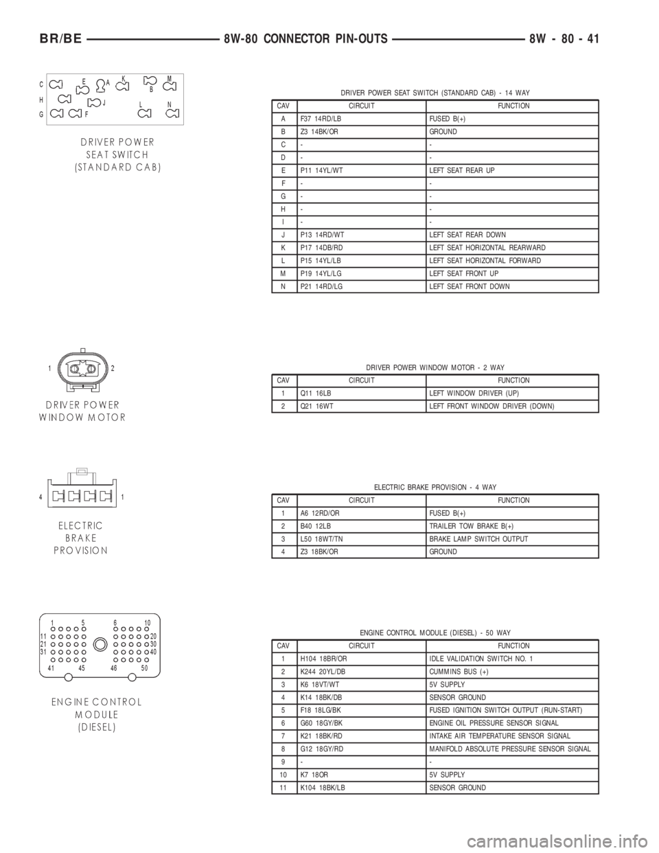
DRIVER POWER SEAT SWITCH (STANDARD CAB) - 14 WAY
CAV CIRCUIT FUNCTION
A F37 14RD/LB FUSED B(+)
B Z3 14BK/OR GROUND
C- -
D- -
E P11 14YL/WT LEFT SEAT REAR UP
F- -
G- -
H- -
I- -
J P13 14RD/WT LEFT SEAT REAR DOWN
K P17 14DB/RD LEFT SEAT HORIZONTAL REARWARD
L P15 14YL/LB LEFT SEAT HORIZONTAL FORWARD
M P19 14YL/LG LEFT SEAT FRONT UP
N P21 14RD/LG LEFT SEAT FRONT DOWN
DRIVER POWER WINDOW MOTOR-2WAY
CAV CIRCUIT FUNCTION
1 Q11 16LB LEFT WINDOW DRIVER (UP)
2 Q21 16WT LEFT FRONT WINDOW DRIVER (DOWN)
ELECTRIC BRAKE PROVISION-4WAY
CAV CIRCUIT FUNCTION
1 A6 12RD/OR FUSED B(+)
2 B40 12LB TRAILER TOW BRAKE B(+)
3 L50 18WT/TN BRAKE LAMP SWITCH OUTPUT
4 Z3 18BK/OR GROUND
ENGINE CONTROL MODULE (DIESEL) - 50 WAY
CAV CIRCUIT FUNCTION
1 H104 18BR/OR IDLE VALIDATION SWITCH NO. 1
2 K244 20YL/DB CUMMINS BUS (+)
3 K6 18VT/WT 5V SUPPLY
4 K14 18BK/DB SENSOR GROUND
5 F18 18LG/BK FUSED IGNITION SWITCH OUTPUT (RUN-START)
6 G60 18GY/BK ENGINE OIL PRESSURE SENSOR SIGNAL
7 K21 18BK/RD INTAKE AIR TEMPERATURE SENSOR SIGNAL
8 G12 18GY/RD MANIFOLD ABSOLUTE PRESSURE SENSOR SIGNAL
9- -
10 K7 18OR 5V SUPPLY
11 K104 18BK/LB SENSOR GROUND
BR/BE8W-80 CONNECTOR PIN-OUTS 8W - 80 - 41
Page 1002 of 2255
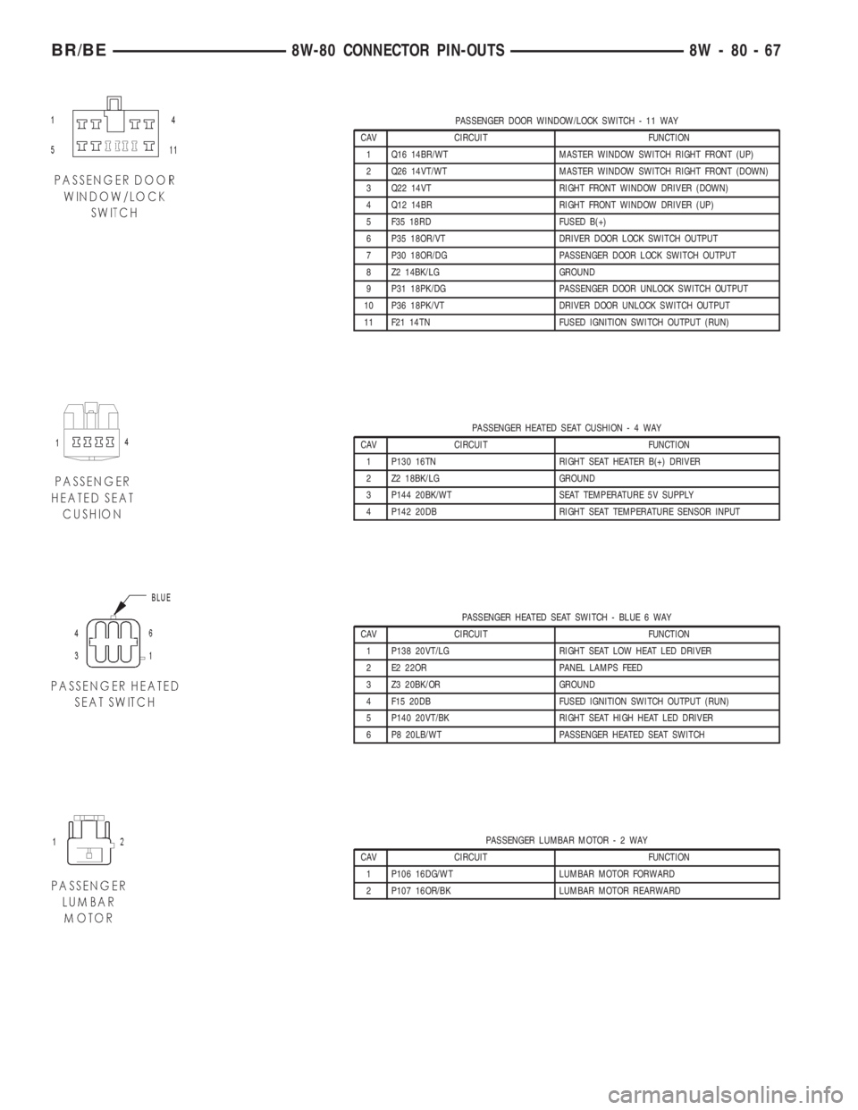
PASSENGER DOOR WINDOW/LOCK SWITCH - 11 WAY
CAV CIRCUIT FUNCTION
1 Q16 14BR/WT MASTER WINDOW SWITCH RIGHT FRONT (UP)
2 Q26 14VT/WT MASTER WINDOW SWITCH RIGHT FRONT (DOWN)
3 Q22 14VT RIGHT FRONT WINDOW DRIVER (DOWN)
4 Q12 14BR RIGHT FRONT WINDOW DRIVER (UP)
5 F35 18RD FUSED B(+)
6 P35 18OR/VT DRIVER DOOR LOCK SWITCH OUTPUT
7 P30 18OR/DG PASSENGER DOOR LOCK SWITCH OUTPUT
8 Z2 14BK/LG GROUND
9 P31 18PK/DG PASSENGER DOOR UNLOCK SWITCH OUTPUT
10 P36 18PK/VT DRIVER DOOR UNLOCK SWITCH OUTPUT
11 F21 14TN FUSED IGNITION SWITCH OUTPUT (RUN)
PASSENGER HEATED SEAT CUSHION-4WAY
CAV CIRCUIT FUNCTION
1 P130 16TN RIGHT SEAT HEATER B(+) DRIVER
2 Z2 18BK/LG GROUND
3 P144 20BK/WT SEAT TEMPERATURE 5V SUPPLY
4 P142 20DB RIGHT SEAT TEMPERATURE SENSOR INPUT
PASSENGER HEATED SEAT SWITCH - BLUE 6 WAY
CAV CIRCUIT FUNCTION
1 P138 20VT/LG RIGHT SEAT LOW HEAT LED DRIVER
2 E2 22OR PANEL LAMPS FEED
3 Z3 20BK/OR GROUND
4 F15 20DB FUSED IGNITION SWITCH OUTPUT (RUN)
5 P140 20VT/BK RIGHT SEAT HIGH HEAT LED DRIVER
6 P8 20LB/WT PASSENGER HEATED SEAT SWITCH
PASSENGER LUMBAR MOTOR-2WAY
CAV CIRCUIT FUNCTION
1 P106 16DG/WT LUMBAR MOTOR FORWARD
2 P107 16OR/BK LUMBAR MOTOR REARWARD
BR/BE8W-80 CONNECTOR PIN-OUTS 8W - 80 - 67
Page 1003 of 2255
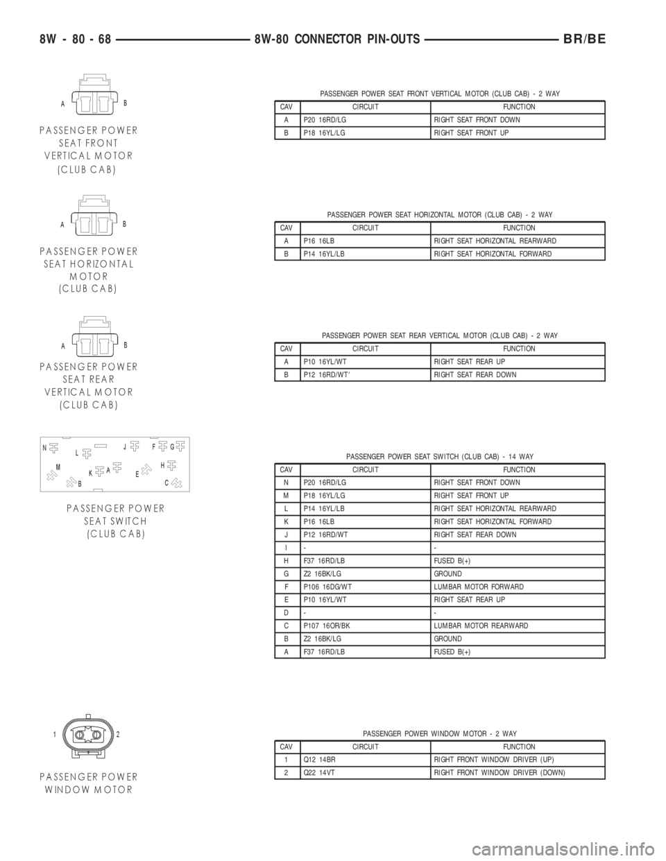
PASSENGER POWER SEAT FRONT VERTICAL MOTOR (CLUB CAB)-2WAY
CAV CIRCUIT FUNCTION
A P20 16RD/LG RIGHT SEAT FRONT DOWN
B P18 16YL/LG RIGHT SEAT FRONT UP
PASSENGER POWER SEAT HORIZONTAL MOTOR (CLUB CAB)-2WAY
CAV CIRCUIT FUNCTION
A P16 16LB RIGHT SEAT HORIZONTAL REARWARD
B P14 16YL/LB RIGHT SEAT HORIZONTAL FORWARD
PASSENGER POWER SEAT REAR VERTICAL MOTOR (CLUB CAB)-2WAY
CAV CIRCUIT FUNCTION
A P10 16YL/WT RIGHT SEAT REAR UP
B P12 16RD/WT8RIGHT SEAT REAR DOWN
PASSENGER POWER SEAT SWITCH (CLUB CAB) - 14 WAY
CAV CIRCUIT FUNCTION
N P20 16RD/LG RIGHT SEAT FRONT DOWN
M P18 16YL/LG RIGHT SEAT FRONT UP
L P14 16YL/LB RIGHT SEAT HORIZONTAL REARWARD
K P16 16LB RIGHT SEAT HORIZONTAL FORWARD
J P12 16RD/WT RIGHT SEAT REAR DOWN
I- -
H F37 16RD/LB FUSED B(+)
G Z2 16BK/LG GROUND
F P106 16DG/WT LUMBAR MOTOR FORWARD
E P10 16YL/WT RIGHT SEAT REAR UP
D- -
C P107 16OR/BK LUMBAR MOTOR REARWARD
B Z2 16BK/LG GROUND
A F37 16RD/LB FUSED B(+)
PASSENGER POWER WINDOW MOTOR-2WAY
CAV CIRCUIT FUNCTION
1 Q12 14BR RIGHT FRONT WINDOW DRIVER (UP)
2 Q22 14VT RIGHT FRONT WINDOW DRIVER (DOWN)
8W - 80 - 68 8W-80 CONNECTOR PIN-OUTSBR/BE
Page 1020 of 2255
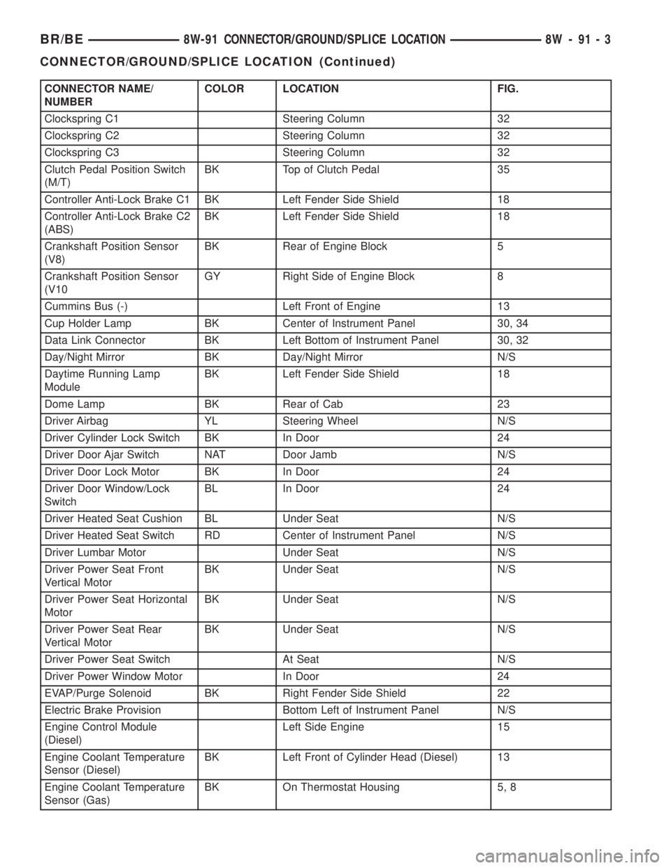
CONNECTOR NAME/
NUMBERCOLOR LOCATION FIG.
Clockspring C1 Steering Column 32
Clockspring C2 Steering Column 32
Clockspring C3 Steering Column 32
Clutch Pedal Position Switch
(M/T)BK Top of Clutch Pedal 35
Controller Anti-Lock Brake C1 BK Left Fender Side Shield 18
Controller Anti-Lock Brake C2
(ABS)BK Left Fender Side Shield 18
Crankshaft Position Sensor
(V8)BK Rear of Engine Block 5
Crankshaft Position Sensor
(V10GY Right Side of Engine Block 8
Cummins Bus (-) Left Front of Engine 13
Cup Holder Lamp BK Center of Instrument Panel 30, 34
Data Link Connector BK Left Bottom of Instrument Panel 30, 32
Day/Night Mirror BK Day/Night Mirror N/S
Daytime Running Lamp
ModuleBK Left Fender Side Shield 18
Dome Lamp BK Rear of Cab 23
Driver Airbag YL Steering Wheel N/S
Driver Cylinder Lock Switch BK In Door 24
Driver Door Ajar Switch NAT Door Jamb N/S
Driver Door Lock Motor BK In Door 24
Driver Door Window/Lock
SwitchBL In Door 24
Driver Heated Seat Cushion BL Under Seat N/S
Driver Heated Seat Switch RD Center of Instrument Panel N/S
Driver Lumbar Motor Under Seat N/S
Driver Power Seat Front
Vertical MotorBK Under Seat N/S
Driver Power Seat Horizontal
MotorBK Under Seat N/S
Driver Power Seat Rear
Vertical MotorBK Under Seat N/S
Driver Power Seat Switch At Seat N/S
Driver Power Window Motor In Door 24
EVAP/Purge Solenoid BK Right Fender Side Shield 22
Electric Brake Provision Bottom Left of Instrument Panel N/S
Engine Control Module
(Diesel)Left Side Engine 15
Engine Coolant Temperature
Sensor (Diesel)BK Left Front of Cylinder Head (Diesel) 13
Engine Coolant Temperature
Sensor (Gas)BK On Thermostat Housing 5, 8
BR/BE8W-91 CONNECTOR/GROUND/SPLICE LOCATION 8W - 91 - 3
CONNECTOR/GROUND/SPLICE LOCATION (Continued)
Page 1023 of 2255
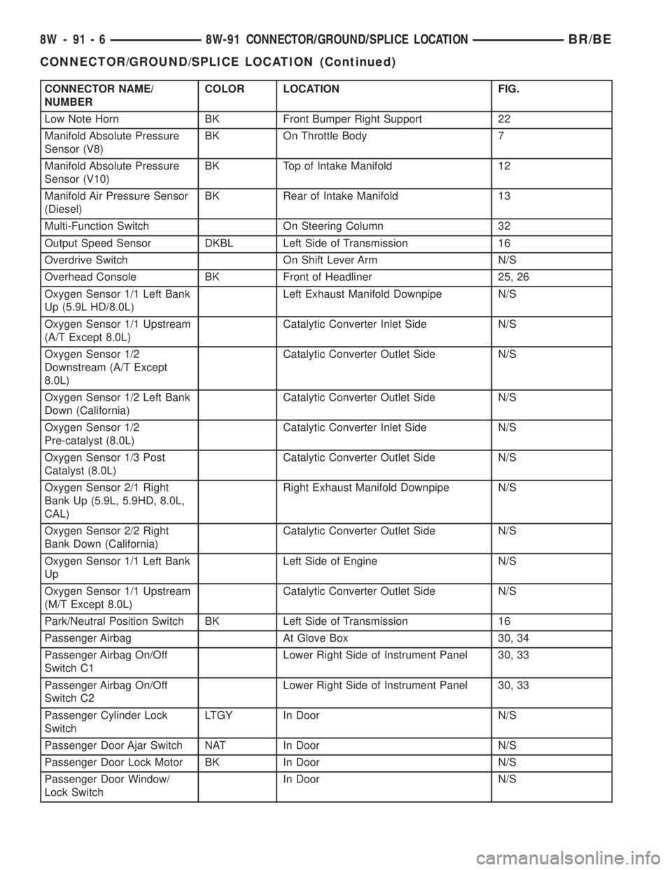
CONNECTOR NAME/
NUMBERCOLOR LOCATION FIG.
Low Note Horn BK Front Bumper Right Support 22
Manifold Absolute Pressure
Sensor (V8)BK On Throttle Body 7
Manifold Absolute Pressure
Sensor (V10)BK Top of Intake Manifold 12
Manifold Air Pressure Sensor
(Diesel)BK Rear of Intake Manifold 13
Multi-Function Switch On Steering Column 32
Output Speed Sensor DKBL Left Side of Transmission 16
Overdrive Switch On Shift Lever Arm N/S
Overhead Console BK Front of Headliner 25, 26
Oxygen Sensor 1/1 Left Bank
Up (5.9L HD/8.0L)Left Exhaust Manifold Downpipe N/S
Oxygen Sensor 1/1 Upstream
(A/T Except 8.0L)Catalytic Converter Inlet Side N/S
Oxygen Sensor 1/2
Downstream (A/T Except
8.0L)Catalytic Converter Outlet Side N/S
Oxygen Sensor 1/2 Left Bank
Down (California)Catalytic Converter Outlet Side N/S
Oxygen Sensor 1/2
Pre-catalyst (8.0L)Catalytic Converter Inlet Side N/S
Oxygen Sensor 1/3 Post
Catalyst (8.0L)Catalytic Converter Outlet Side N/S
Oxygen Sensor 2/1 Right
Bank Up (5.9L, 5.9HD, 8.0L,
CAL)Right Exhaust Manifold Downpipe N/S
Oxygen Sensor 2/2 Right
Bank Down (California)Catalytic Converter Outlet Side N/S
Oxygen Sensor 1/1 Left Bank
UpLeft Side of Engine N/S
Oxygen Sensor 1/1 Upstream
(M/T Except 8.0L)Catalytic Converter Outlet Side N/S
Park/Neutral Position Switch BK Left Side of Transmission 16
Passenger Airbag At Glove Box 30, 34
Passenger Airbag On/Off
Switch C1Lower Right Side of Instrument Panel 30, 33
Passenger Airbag On/Off
Switch C2Lower Right Side of Instrument Panel 30, 33
Passenger Cylinder Lock
SwitchLTGY In Door N/S
Passenger Door Ajar Switch NAT In Door N/S
Passenger Door Lock Motor BK In Door N/S
Passenger Door Window/
Lock SwitchIn Door N/S
8W - 91 - 6 8W-91 CONNECTOR/GROUND/SPLICE LOCATIONBR/BE
CONNECTOR/GROUND/SPLICE LOCATION (Continued)
Page 1024 of 2255
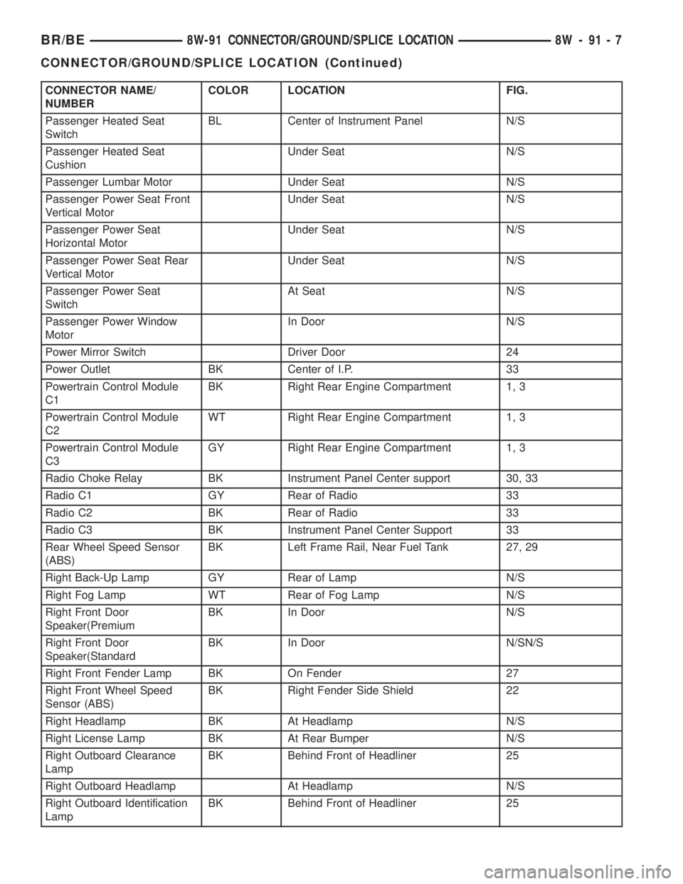
CONNECTOR NAME/
NUMBERCOLOR LOCATION FIG.
Passenger Heated Seat
SwitchBL Center of Instrument Panel N/S
Passenger Heated Seat
CushionUnder Seat N/S
Passenger Lumbar Motor Under Seat N/S
Passenger Power Seat Front
Vertical MotorUnder Seat N/S
Passenger Power Seat
Horizontal MotorUnder Seat N/S
Passenger Power Seat Rear
Vertical MotorUnder Seat N/S
Passenger Power Seat
SwitchAt Seat N/S
Passenger Power Window
MotorIn Door N/S
Power Mirror Switch Driver Door 24
Power Outlet BK Center of I.P. 33
Powertrain Control Module
C1BK Right Rear Engine Compartment 1, 3
Powertrain Control Module
C2WT Right Rear Engine Compartment 1, 3
Powertrain Control Module
C3GY Right Rear Engine Compartment 1, 3
Radio Choke Relay BK Instrument Panel Center support 30, 33
Radio C1 GY Rear of Radio 33
Radio C2 BK Rear of Radio 33
Radio C3 BK Instrument Panel Center Support 33
Rear Wheel Speed Sensor
(ABS)BK Left Frame Rail, Near Fuel Tank 27, 29
Right Back-Up Lamp GY Rear of Lamp N/S
Right Fog Lamp WT Rear of Fog Lamp N/S
Right Front Door
Speaker(PremiumBK In Door N/S
Right Front Door
Speaker(StandardBK In Door N/SN/S
Right Front Fender Lamp BK On Fender 27
Right Front Wheel Speed
Sensor (ABS)BK Right Fender Side Shield 22
Right Headlamp BK At Headlamp N/S
Right License Lamp BK At Rear Bumper N/S
Right Outboard Clearance
LampBK Behind Front of Headliner 25
Right Outboard Headlamp At Headlamp N/S
Right Outboard Identification
LampBK Behind Front of Headliner 25
BR/BE8W-91 CONNECTOR/GROUND/SPLICE LOCATION 8W - 91 - 7
CONNECTOR/GROUND/SPLICE LOCATION (Continued)
Page 2042 of 2255
INSTALLATION
(1) Position flag cover on door.
(2) Install nuts attaching mirror flag cover to door
frame.
(3) Install flag door seal.
(4) Install door trim panel. (Refer to 23 - BODY/
DOOR - FRONT/TRIM PANEL - INSTALLATION)
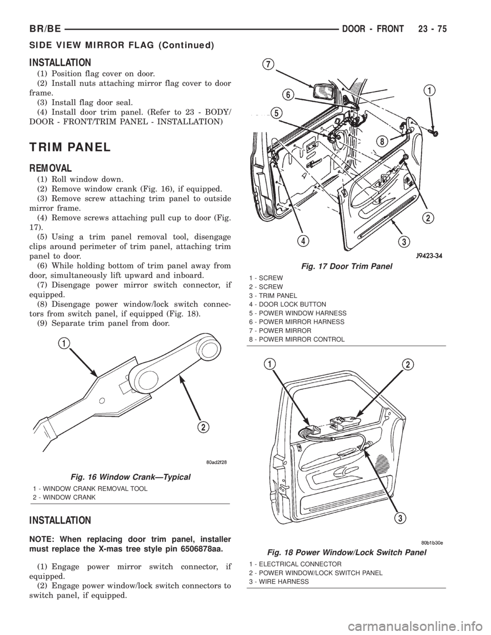
TRIM PANEL
REMOVAL
(1) Roll window down.
(2) Remove window crank (Fig. 16), if equipped.
(3) Remove screw attaching trim panel to outside
mirror frame.
(4) Remove screws attaching pull cup to door (Fig.
17).
(5) Using a trim panel removal tool, disengage
clips around perimeter of trim panel, attaching trim
panel to door.
(6) While holding bottom of trim panel away from
door, simultaneously lift upward and inboard.
(7) Disengage power mirror switch connector, if
equipped.
(8) Disengage power window/lock switch connec-
tors from switch panel, if equipped (Fig. 18).
(9) Separate trim panel from door.
INSTALLATION
NOTE: When replacing door trim panel, installer
must replace the X-mas tree style pin 6506878aa.
(1) Engage power mirror switch connector, if
equipped.
(2) Engage power window/lock switch connectors to
switch panel, if equipped.
Fig. 16 Window CrankÐTypical
1 - WINDOW CRANK REMOVAL TOOL
2 - WINDOW CRANK
Fig. 17 Door Trim Panel
1 - SCREW
2 - SCREW
3 - TRIM PANEL
4 - DOOR LOCK BUTTON
5 - POWER WINDOW HARNESS
6 - POWER MIRROR HARNESS
7 - POWER MIRROR
8 - POWER MIRROR CONTROL
Fig. 18 Power Window/Lock Switch Panel
1 - ELECTRICAL CONNECTOR
2 - POWER WINDOW/LOCK SWITCH PANEL
3 - WIRE HARNESS
BR/BEDOOR - FRONT 23 - 75
SIDE VIEW MIRROR FLAG (Continued)
Page 2123 of 2255
The optional air conditioner for all models is
designed for the use of non-CFC, R-134a refrigerant.
The air conditioning system has an evaporator to cool
and dehumidify the incoming air prior to blending it
with the heated air. This air conditioning system
uses a fixed orifice tube in the middle of the liquid
line to meter refrigerant flow to the evaporator coil.
To maintain minimum evaporator temperature and
prevent evaporator freezing, the a/c low pressure
switch on the accumulator cycles the compressor
clutch.
OPERATION - REFRIGERANT SYSTEM SERVICE
PORT
The high pressure service port is located on the liq-
uid line between the condenser and the evaporator,
near the front of the engine compartment. The low
pressure service port is located on the suction line,
near the accumulator outlet.
Each of the service ports has a threaded plastic
protective cap installed over it from the factory. After
servicing the refrigerant system, always reinstall
both of the service port caps.
DIAGNOSIS AND TESTING - A/C
PERFORMANCE
The air conditioning system is designed to provide
the passenger compartment with low temperature
and low humidity air. The evaporator, located in the
HVAC housing on the dash panel below the instru-
ment panel, is cooled to temperatures near the freez-
ing point. As warm damp air passes through the
cooled evaporator, the air transfers its heat to the
refrigerant in the evaporator tubes and the moisture
in the air condenses on the evaporator fins. During
periods of high heat and humidity, an air condition-
ing system will be more effective in the recirculation
mode (Max-A/C). With the system in the recirculation
mode, only air from the passenger compartment
passes through the evaporator. As the passenger com-
partment air dehumidifies, the air conditioning sys-
tem performance levels improve.
Humidity has an important bearing on the temper-
ature of the air delivered to the interior of the vehi-
cle. It is important to understand the effect that
humidity has on the performance of the air condition-
ing system. When humidity is high, the evaporator
has to perform a double duty. It must lower the air
temperature, and it must lower the temperature of
the moisture in the air that condenses on the evapo-
rator fins. Condensing the moisture in the air trans-
fers heat energy into the evaporator fins and tubing.This reduces the amount of heat the evaporator can
absorb from the air. High humidity greatly reduces
the ability of the evaporator to lower the temperature
of the air.
However, evaporator capacity used to reduce the
amount of moisture in the air is not wasted. Wring-
ing some of the moisture out of the air entering the
vehicle adds to the comfort of the passengers.
Although, an owner may expect too much from their
air conditioning system on humid days. A perfor-
mance test is the best way to determine whether the
system is performing up to standard. This test also
provides valuable clues as to the possible cause of
trouble with the air conditioning system.
Before proceeding, (Refer to 24 - HEATING & AIR
CONDITIONING/PLUMBING - WARNING) and
(Refer to 24 - HEATING & AIR CONDITIONING/
PLUMBING - CAUTION). The air temperature in
the test room and in the vehicle must be a minimum
of 21É C (70É F) for this test.
(1) Connect a tachometer and a manifold gauge
set.
(2) Set the a/c heater mode control switch knob to
the recirculation mode (Max-A/C) position, the tem-
perature control knob to the full cool position, and
the blower motor switch to the highest speed posi-
tion.
(3) Start the engine and hold the idle speed at
1,000 rpm with the compressor clutch engaged. If the
compressor clutch does not engage, (Refer to 24 -
HEATING & AIR CONDITIONING/CONTROLS/A/C
COMPRESSOR CLUTCH COIL - DIAGNOSIS AND
TESTING).
(4) The engine should be at operating temperature.
The doors and windows must be closed and the hood
must be mostly closed.
(5) Insert a thermometer in the driver side center
A/C (panel) outlet. Operate the engine for five min-
utes.
(6) The compressor clutch may cycle, depending
upon the ambient temperature and humidity. If the
clutch cycles, unplug the a/c low pressure switch wire
harness connector from the switch located on the
accumulator (Fig. 2). Place a jumper wire between
the two cavities of the a/c low pressure switch wire
harness connector.
24 - 2 HEATING & AIR CONDITIONINGBR/BE
HEATING & AIR CONDITIONING (Continued)