ECU DODGE RAM 2002 Service Repair Manual
[x] Cancel search | Manufacturer: DODGE, Model Year: 2002, Model line: RAM, Model: DODGE RAM 2002Pages: 2255, PDF Size: 62.07 MB
Page 2176 of 2255
ACCUMULATOR
DESCRIPTION
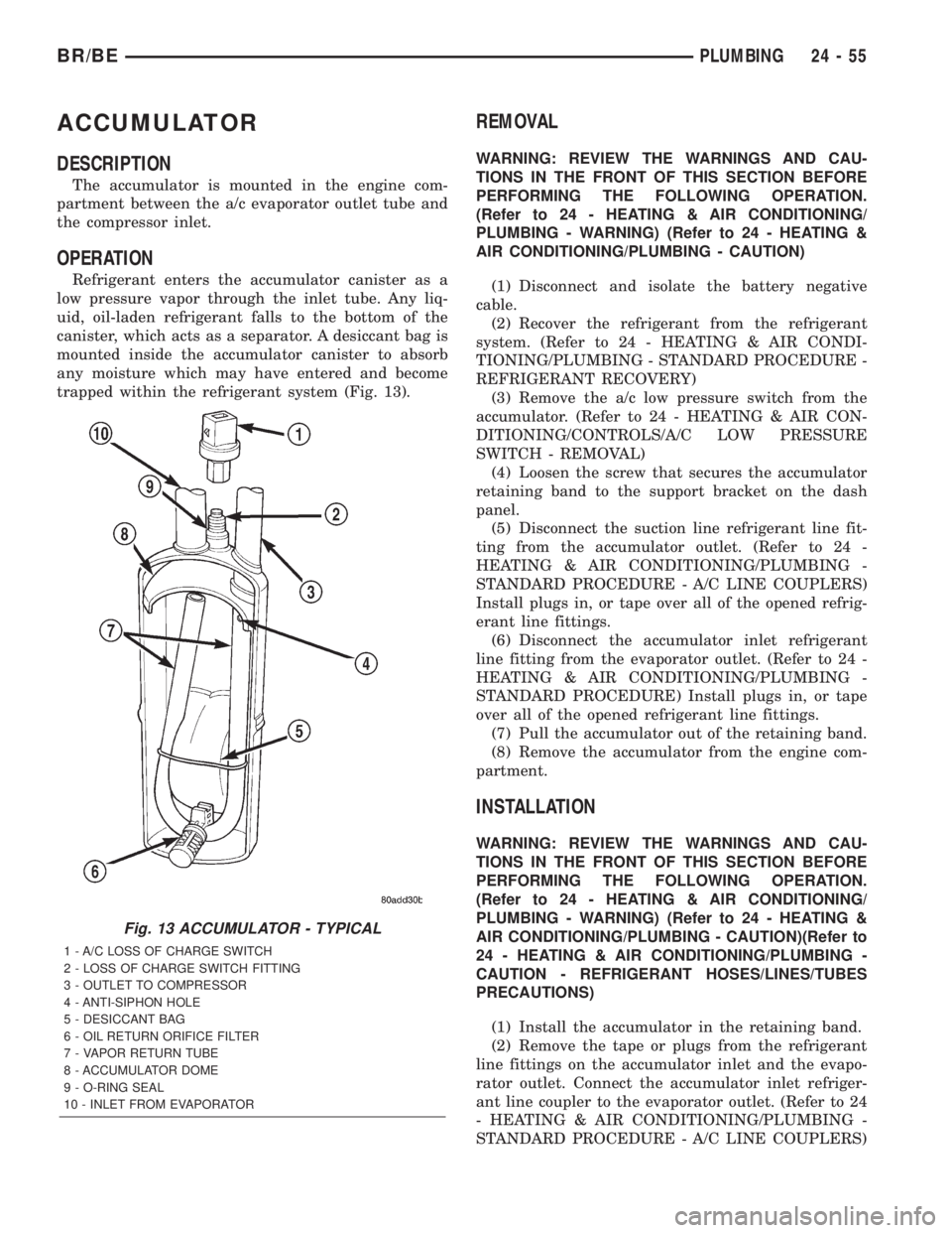
The accumulator is mounted in the engine com-
partment between the a/c evaporator outlet tube and
the compressor inlet.
OPERATION
Refrigerant enters the accumulator canister as a
low pressure vapor through the inlet tube. Any liq-
uid, oil-laden refrigerant falls to the bottom of the
canister, which acts as a separator. A desiccant bag is
mounted inside the accumulator canister to absorb
any moisture which may have entered and become
trapped within the refrigerant system (Fig. 13).
REMOVAL
WARNING: REVIEW THE WARNINGS AND CAU-
TIONS IN THE FRONT OF THIS SECTION BEFORE
PERFORMING THE FOLLOWING OPERATION.
(Refer to 24 - HEATING & AIR CONDITIONING/
PLUMBING - WARNING) (Refer to 24 - HEATING &
AIR CONDITIONING/PLUMBING - CAUTION)
(1) Disconnect and isolate the battery negative
cable.
(2) Recover the refrigerant from the refrigerant
system. (Refer to 24 - HEATING & AIR CONDI-
TIONING/PLUMBING - STANDARD PROCEDURE -
REFRIGERANT RECOVERY)
(3) Remove the a/c low pressure switch from the
accumulator. (Refer to 24 - HEATING & AIR CON-
DITIONING/CONTROLS/A/C LOW PRESSURE
SWITCH - REMOVAL)
(4) Loosen the screw that secures the accumulator
retaining band to the support bracket on the dash
panel.
(5) Disconnect the suction line refrigerant line fit-
ting from the accumulator outlet. (Refer to 24 -
HEATING & AIR CONDITIONING/PLUMBING -
STANDARD PROCEDURE - A/C LINE COUPLERS)
Install plugs in, or tape over all of the opened refrig-
erant line fittings.
(6) Disconnect the accumulator inlet refrigerant
line fitting from the evaporator outlet. (Refer to 24 -
HEATING & AIR CONDITIONING/PLUMBING -
STANDARD PROCEDURE) Install plugs in, or tape
over all of the opened refrigerant line fittings.
(7) Pull the accumulator out of the retaining band.
(8) Remove the accumulator from the engine com-
partment.
INSTALLATION
WARNING: REVIEW THE WARNINGS AND CAU-
TIONS IN THE FRONT OF THIS SECTION BEFORE
PERFORMING THE FOLLOWING OPERATION.
(Refer to 24 - HEATING & AIR CONDITIONING/
PLUMBING - WARNING) (Refer to 24 - HEATING &
AIR CONDITIONING/PLUMBING - CAUTION)(Refer to
24 - HEATING & AIR CONDITIONING/PLUMBING -
CAUTION - REFRIGERANT HOSES/LINES/TUBES
PRECAUTIONS)
(1) Install the accumulator in the retaining band.
(2) Remove the tape or plugs from the refrigerant
line fittings on the accumulator inlet and the evapo-
rator outlet. Connect the accumulator inlet refriger-
ant line coupler to the evaporator outlet. (Refer to 24
- HEATING & AIR CONDITIONING/PLUMBING -
STANDARD PROCEDURE - A/C LINE COUPLERS)
Fig. 13 ACCUMULATOR - TYPICAL
1 - A/C LOSS OF CHARGE SWITCH
2 - LOSS OF CHARGE SWITCH FITTING
3 - OUTLET TO COMPRESSOR
4 - ANTI-SIPHON HOLE
5 - DESICCANT BAG
6 - OIL RETURN ORIFICE FILTER
7 - VAPOR RETURN TUBE
8 - ACCUMULATOR DOME
9 - O-RING SEAL
10 - INLET FROM EVAPORATOR
BR/BEPLUMBING 24 - 55
Page 2177 of 2255
(3) Tighten the accumulator retaining band screw
to 4.5 N´m (40 in. lbs.).
(4) Remove the tape or plugs from the refrigerant
line fittings on the suction line and the accumulator
outlet. Connect the suction line refrigerant line cou-
pler to the accumulator outlet. (Refer to 24 - HEAT-
ING & AIR CONDITIONING/PLUMBING -
STANDARD PROCEDURE - A/C LINE COUPLERS)
(5) Reinstall the a/c low pressure switch on the
accumulator. (Refer to 24 - HEATING & AIR CON-
DITIONING/CONTROLS/A/C LOW PRESSURE
SWITCH - INSTALLATION)
(6) Connect the battery negative cable.
(7) Evacuate the refrigerant system. (Refer to 24 -
HEATING & AIR CONDITIONING/PLUMBING -
STANDARD PROCEDURE - REFRIGERANT SYS-
TEM EVACUATE)
(8) Charge the refrigerant system. (Refer to 24 -
HEATING & AIR CONDITIONING/PLUMBING -
STANDARD PROCEDURE - REFRIGERANT SYS-
TEM CHARGE)
NOTE: If the accumulator is replaced, add 60 milli-
liters (2 fluid ounces) of refrigerant oil to the refrig-
erant system. Use only refrigerant oil of the type
recommended for the compressor in the vehicle.
HEATER CORE
DESCRIPTION
The heater core is located in the HVAC housing,
under the instrument panel. It is a heat exchanger
made of rows of tubes and fins.
The heater core is not repairable and if damaged it
must be replaced.
OPERATION
Engine coolant is circulated through heater hoses
to the heater core at all times. As the coolant flows
through the heater core, heat removed from the
engine is transferred to the heater core fins and
tubes. Air directed through the heater core picks up
the heat from the heater core fins. The blend door
allows control of the heater output air temperature
by controlling how much of the air flowing through
the HVAC housing is directed through the heater
core. The blower motor speed controls the volume of
air flowing through the HVAC housing.
The heater core cannot be repaired and, if faulty or
damaged, it must be replaced.
REMOVAL
(1) Remove the HVAC housing from the vehicle.
(Refer to 24 - HEATING & AIR CONDITIONING/
DISTRIBUTION/HVAC HOUSING - REMOVAL)(2) Remove the screws and retainers that secure
the heater core to the HVAC housing.
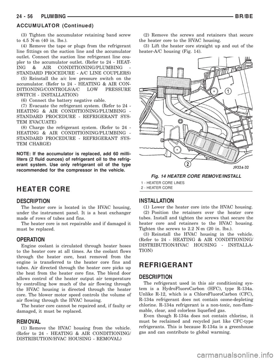
(3) Lift the heater core straight up and out of the
heater-A/C housing (Fig. 14).
INSTALLATION
(1) Lower the heater core into the HVAC housing.
(2) Position the retainers over the heater core
tubes. Install and tighten the screws that secure the
heater core and retainers to the HVAC housing.
Tighten the screws to 2.2 N´m (20 in. lbs.).
(3) Reinstall the HVAC housing in the vehicle.
(Refer to 24 - HEATING & AIR CONDITIONING/
DISTRIBUTION/HVAC HOUSING - INSTALLA-
TION)
REFRIGERANT
DESCRIPTION
The refrigerant used in this air conditioning sys-
tem is a HydroFluoroCarbon (HFC), type R-134a.
Unlike R-12, which is a ChloroFluoroCarbon (CFC),
R-134a refrigerant does not contain ozone-depleting
chlorine. R-134a refrigerant is a non-toxic, non-flam-
mable, clear, and colorless liquefied gas.
Even though R-134a does not contain chlorine, it
must be reclaimed and recycled just like CFC-type
refrigerants. This is because R-134a is a greenhouse
gas and can contribute to global warming.
Fig. 14 HEATER CORE REMOVE/INSTALL
1 - HEATER CORE LINES
2 - HEATER CORE
24 - 56 PLUMBINGBR/BE
ACCUMULATOR (Continued)
Page 2195 of 2255
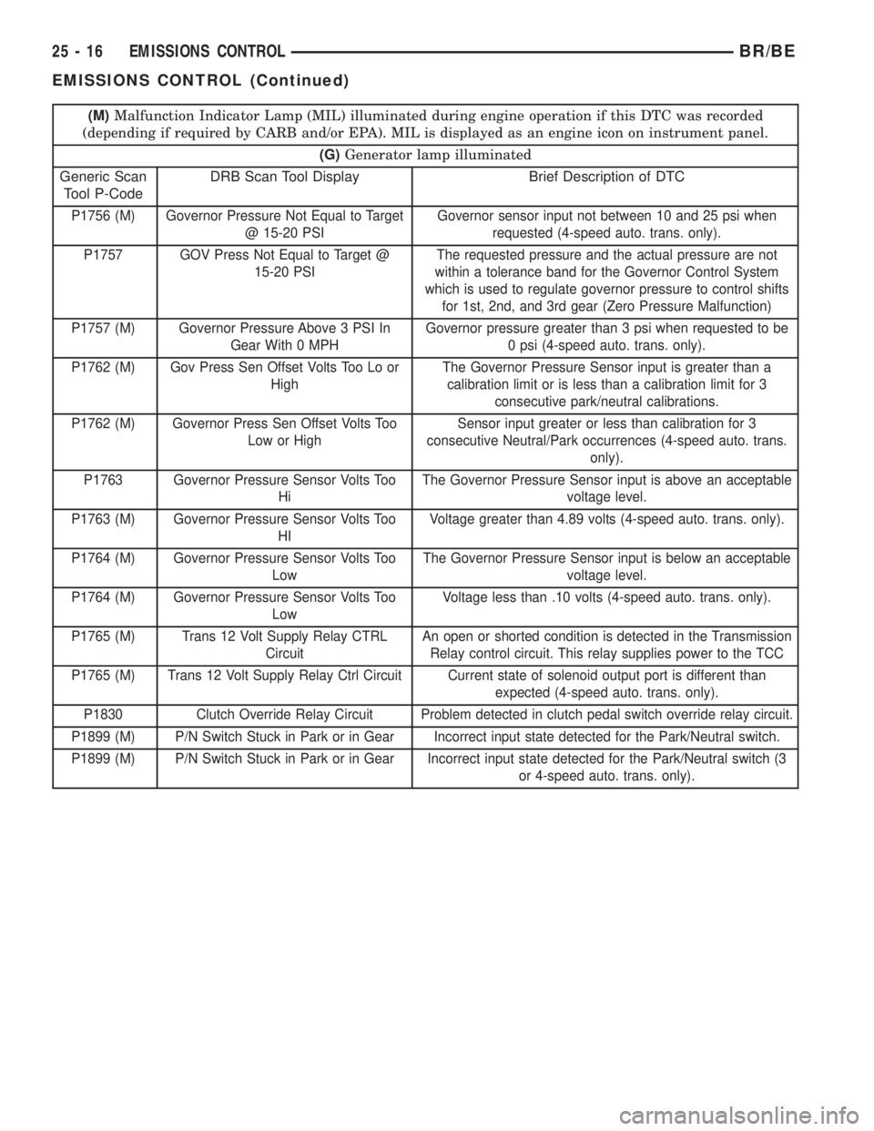
(M)Malfunction Indicator Lamp (MIL) illuminated during engine operation if this DTC was recorded
(depending if required by CARB and/or EPA). MIL is displayed as an engine icon on instrument panel.
(G)Generator lamp illuminated
Generic Scan
Tool P-CodeDRB Scan Tool Display Brief Description of DTC
P1756 (M) Governor Pressure Not Equal to Target
@ 15-20 PSIGovernor sensor input not between 10 and 25 psi when
requested (4-speed auto. trans. only).
P1757 GOV Press Not Equal to Target @
15-20 PSIThe requested pressure and the actual pressure are not
within a tolerance band for the Governor Control System
which is used to regulate governor pressure to control shifts
for 1st, 2nd, and 3rd gear (Zero Pressure Malfunction)
P1757 (M) Governor Pressure Above 3 PSI In
Gear With 0 MPHGovernor pressure greater than 3 psi when requested to be
0 psi (4-speed auto. trans. only).
P1762 (M) Gov Press Sen Offset Volts Too Lo or
HighThe Governor Pressure Sensor input is greater than a
calibration limit or is less than a calibration limit for 3
consecutive park/neutral calibrations.
P1762 (M) Governor Press Sen Offset Volts Too
Low or HighSensor input greater or less than calibration for 3
consecutive Neutral/Park occurrences (4-speed auto. trans.
only).
P1763 Governor Pressure Sensor Volts Too
HiThe Governor Pressure Sensor input is above an acceptable
voltage level.
P1763 (M) Governor Pressure Sensor Volts Too
HIVoltage greater than 4.89 volts (4-speed auto. trans. only).
P1764 (M) Governor Pressure Sensor Volts Too
LowThe Governor Pressure Sensor input is below an acceptable
voltage level.
P1764 (M) Governor Pressure Sensor Volts Too
LowVoltage less than .10 volts (4-speed auto. trans. only).
P1765 (M) Trans 12 Volt Supply Relay CTRL
CircuitAn open or shorted condition is detected in the Transmission
Relay control circuit. This relay supplies power to the TCC
P1765 (M) Trans 12 Volt Supply Relay Ctrl Circuit Current state of solenoid output port is different than
expected (4-speed auto. trans. only).
P1830 Clutch Override Relay Circuit Problem detected in clutch pedal switch override relay circuit.
P1899 (M) P/N Switch Stuck in Park or in Gear Incorrect input state detected for the Park/Neutral switch.
P1899 (M) P/N Switch Stuck in Park or in Gear Incorrect input state detected for the Park/Neutral switch (3
or 4-speed auto. trans. only).
25 - 16 EMISSIONS CONTROLBR/BE
EMISSIONS CONTROL (Continued)
Page 2196 of 2255
DESCRIPTION - TASK MANAGER
The PCM is responsible for efficiently coordinating
the operation of all the emissions-related compo-
nents. The PCM is also responsible for determining if
the diagnostic systems are operating properly. The
software designed to carry out these responsibilities
is call the 'Task Manager'.
DESCRIPTION - MONITORED SYSTEMS
There are new electronic circuit monitors that
check fuel, emission, engine and ignition perfor-
mance. These monitors use information from various
sensor circuits to indicate the overall operation of the
fuel, engine, ignition and emission systems and thus
the emissions performance of the vehicle.
The fuel, engine, ignition and emission systems
monitors do not indicate a specific component prob-
lem. They do indicate that there is an implied prob-
lem within one of the systems and that a specific
problem must be diagnosed.
If any of these monitors detect a problem affecting
vehicle emissions, the Malfunction Indicator Lamp
(MIL) will be illuminated. These monitors generate
Diagnostic Trouble Codes that can be displayed with
the MIL or a scan tool.
The following is a list of the system monitors:
²Misfire Monitor
²Fuel System Monitor
²Oxygen Sensor Monitor
²Oxygen Sensor Heater Monitor
²Catalyst Monitor
²Leak Detection Pump Monitor (if equipped)
All these system monitors require two consecutive
trips with the malfunction present to set a fault.
Refer to the appropriate Powertrain Diagnos-
tics Procedures manual for diagnostic proce-
dures.
The following is an operation and description of
each system monitor :
OXYGEN SENSOR (O2S) MONITOR
Effective control of exhaust emissions is achieved
by an oxygen feedback system. The most important
element of the feedback system is the O2S. The O2S
is located in the exhaust path. Once it reaches oper-
ating temperature 300É to 350ÉC (572É to 662ÉF), the
sensor generates a voltage that is inversely propor-
tional to the amount of oxygen in the exhaust. The
information obtained by the sensor is used to calcu-
late the fuel injector pulse width. This maintains a
14.7 to 1 Air Fuel (A/F) ratio. At this mixture ratio,
the catalyst works best to remove hydrocarbons (HC),
carbon monoxide (CO) and nitrogen oxide (NOx) from
the exhaust.
The O2S is also the main sensing element for the
Catalyst and Fuel Monitors.The O2S can fail in any or all of the following
manners:
²slow response rate
²reduced output voltage
²dynamic shift
²shorted or open circuits
Response rate is the time required for the sensor to
switch from lean to rich once it is exposed to a richer
than optimum A/F mixture or vice versa. As the sen-
sor starts malfunctioning, it could take longer to
detect the changes in the oxygen content of the
exhaust gas.
The output voltage of the O2S ranges from 0 to 1
volt. A good sensor can easily generate any output
voltage in this range as it is exposed to different con-
centrations of oxygen. To detect a shift in the A/F
mixture (lean or rich), the output voltage has to
change beyond a threshold value. A malfunctioning
sensor could have difficulty changing beyond the
threshold value.
OXYGEN SENSOR HEATER MONITOR
If there is an oxygen sensor (O2S) shorted to voltage
DTC, as well as a O2S heater DTC, the O2S fault
MUST be repaired first. Before checking the O2S fault,
verify that the heater circuit is operating correctly.
Effective control of exhaust emissions is achieved
by an oxygen feedback system. The most important
element of the feedback system is the O2S. The O2S
is located in the exhaust path. Once it reaches oper-
ating temperature 300É to 350ÉC (572 É to 662ÉF), the
sensor generates a voltage that is inversely propor-
tional to the amount of oxygen in the exhaust. The
information obtained by the sensor is used to calcu-
late the fuel injector pulse width. This maintains a
14.7 to 1 Air Fuel (A/F) ratio. At this mixture ratio,
the catalyst works best to remove hydrocarbons (HC),
carbon monoxide (CO) and nitrogen oxide (NOx) from
the exhaust.
The voltage readings taken from the O2S sensor
are very temperature sensitive. The readings are not
accurate below 300ÉC. Heating of the O2S sensor is
done to allow the engine controller to shift to closed
loop control as soon as possible. The heating element
used to heat the O2S sensor must be tested to ensure
that it is heating the sensor properly.
The O2S sensor circuit is monitored for a drop in
voltage. The sensor output is used to test the heater
by isolating the effect of the heater element on the
O2S sensor output voltage from the other effects.
LEAK DETECTION PUMP MONITOR (IF EQUIPPED)
The leak detection assembly incorporates two pri-
mary functions: it must detect a leak in the evapora-
tive system and seal the evaporative system so the
leak detection test can be run.
BR/BEEMISSIONS CONTROL 25 - 17
EMISSIONS CONTROL (Continued)
Page 2201 of 2255
MIL Illumination
The PCM Task Manager carries out the illumina-
tion of the MIL. The Task Manager triggers MIL illu-
mination upon test failure, depending on monitor
failure criteria.
The Task Manager Screen shows both a Requested
MIL state and an Actual MIL state. When the MIL is
illuminated upon completion of a test for a third trip,
the Requested MIL state changes to OFF. However,
the MIL remains illuminated until the next key
cycle. (On some vehicles, the MIL will actually turn
OFF during the third key cycle) During the key cycle
for the third good trip, the Requested MIL state is
OFF, while the Actual MILL state is ON. After the
next key cycle, the MIL is not illuminated and both
MIL states read OFF.
Diagnostic Trouble Codes (DTCs)
With OBD II, different DTC faults have different
priorities according to regulations. As a result, the
priorities determine MIL illumination and DTC era-
sure. DTCs are entered according to individual prior-
ity. DTCs with a higher priority overwrite lower
priority DTCs.
Priorities
²Priority 0 ÐNon-emissions related trouble codes
²Priority 1 Ð One trip failure of a two trip fault
for non-fuel system and non-misfire.
²Priority 2 Ð One trip failure of a two trip fault
for fuel system (rich/lean) or misfire.
²Priority3ÐTwotrip failure for a non-fuel sys-
tem and non-misfire or matured one trip comprehen-
sive component fault.
²Priority4ÐTwotrip failure or matured fault
for fuel system (rich/lean) and misfire or one trip cat-
alyst damaging misfire.
Non-emissions related failures have no priority.
One trip failures of two trip faults have low priority.
Two trip failures or matured faults have higher pri-
ority. One and two trip failures of fuel system and
misfire monitor take precedence over non-fuel system
and non-misfire failures.
DTC Self Erasure
With one trip components or systems, the MIL is
illuminated upon test failure and DTCs are stored.
Two trip monitors are components requiring failure
in two consecutive trips for MIL illumination. Upon
failure of the first test, the Task Manager enters a
maturing code. If the component fails the test for a
second time the code matures and a DTC is set.
After three good trips the MIL is extinguished and
the Task Manager automatically switches the trip
counter to a warm-up cycle counter. DTCs are auto-matically erased following 40 warm-up cycles if the
component does not fail again.
For misfire and fuel system monitors, the compo-
nent must pass the test under a Similar Conditions
Window in order to record a good trip. A Similar Con-
ditions Window is when engine RPM is within 375
RPM and load is within 10% of when the fault
occurred.
NOTE: It is important to understand that a compo-
nent does not have to fail under a similar window of
operation to mature. It must pass the test under a
Similar Conditions Window when it failed to record
a Good Trip for DTC erasure for misfire and fuel
system monitors.
DTCs can be erased anytime with a DRB III. Eras-
ing the DTC with the DRB III erases all OBD II
information. The DRB III automatically displays a
warning that erasing the DTC will also erase all
OBD II monitor data. This includes all counter infor-
mation for warm-up cycles, trips and Freeze Frame.
Trip Indicator
TheTripis essential for running monitors and
extinguishing the MIL. In OBD II terms, a trip is a
set of vehicle operating conditions that must be met
for a specific monitor to run. All trips begin with a
key cycle.
Good Trip
The Good Trip counters are as follows:
²Specific Good Trip
²Fuel System Good Trip
²Misfire Good Trip
²Alternate Good Trip (appears as a Global Good
Trip on DRB III)
²Comprehensive Components
²Major Monitor
²Warm-Up Cycles
Specific Good Trip
The term Good Trip has different meanings
depending on the circumstances:
²If the MIL is OFF, a trip is defined as when the
Oxygen Sensor Monitor and the Catalyst Monitor
have been completed in the same drive cycle.
²If the MIL is ON and a DTC was set by the Fuel
Monitor or Misfire Monitor (both continuous moni-
tors), the vehicle must be operated in the Similar
Condition Window for a specified amount of time.
²If the MIL is ON and a DTC was set by a Task
Manager commanded once-per-trip monitor (such as
the Oxygen Sensor Monitor, Catalyst Monitor, Purge
Flow Monitor, Leak Detection Pump Monitor, EGR
Monitor or Oxygen Sensor Heater Monitor), a good
trip is when the monitor is passed on the next start-
up.
25 - 22 EMISSIONS CONTROLBR/BE
EMISSIONS CONTROL (Continued)
Page 2213 of 2255
INSTALLATION
(1) Install solenoid assembly to support bracket.
(2) Connect vacuum harness.
(3) Connect wiring connector.
FUEL FILLER CAP
DESCRIPTION
The plastic fuel tank filler tube cap is threaded
onto the end of the fuel fill tube. Certain models are
equipped with a 1/4 turn cap.
OPERATION
The loss of any fuel or vapor out of fuel filler tube
is prevented by the use of a pressure-vacuum fuel fill
cap. Relief valves inside the cap will release fuel tank
pressure at predetermined pressures. Fuel tank vac-
uum will also be released at predetermined values.
This cap must be replaced by a similar unit if
replacement is necessary. This is in order for the sys-
tem to remain effective.
CAUTION: Remove fill cap before servicing any fuel
system component to relieve tank pressure. If
equipped with a Leak Detection Pump (LDP), the
cap must be tightened securely. If cap is left loose,
a Diagnostic Trouble Code (DTC) may be set.
REMOVAL/INSTALLATION
If replacement of the 1/4 turn fuel tank filler tube
cap is necessary, it must be replaced with an identi-
cal cap to be sure of correct system operation.
CAUTION: Remove the fuel tank filler tube cap to
relieve fuel tank pressure. The cap must be
removed prior to disconnecting any fuel system
component or before draining the fuel tank.
LEAK DETECTION PUMP
DESCRIPTION
The Leak Detection Pump (LDP) is used only with
certain emission packages.
The LDP is a device used to detect a leak in the
evaporative system.
The pump contains a 3 port solenoid, a pump that
contains a switch, a spring loaded canister vent valve
seal, 2 check valves and a spring/diaphragm.
OPERATION
Immediately after a cold start, engine temperature
between 40ÉF and 86ÉF, the 3 port solenoid is briefly
energized. This initializes the pump by drawing airinto the pump cavity and also closes the vent seal.
During non-test test conditions, the vent seal is held
open by the pump diaphragm assembly which pushes
it open at the full travel position. The vent seal will
remain closed while the pump is cycling. This is due
to the operation of the 3 port solenoid which prevents
the diaphragm assembly from reaching full travel.
After the brief initialization period, the solenoid is
de-energized, allowing atmospheric pressure to enter
the pump cavity. This permits the spring to drive the
diaphragm which forces air out of the pump cavity
and into the vent system. When the solenoid is ener-
gized and de-energized, the cycle is repeated creating
flow in typical diaphragm pump fashion. The pump
is controlled in 2 modes:
PUMP MODE:The pump is cycled at a fixed rate
to achieve a rapid pressure build in order to shorten
the overall test time.
TEST MODE:The solenoid is energized with a
fixed duration pulse. Subsequent fixed pulses occur
when the diaphragm reaches the switch closure
point.
The spring in the pump is set so that the system
will achieve an equalized pressure of about 7.5 inches
of water.
When the pump starts, the cycle rate is quite high.
As the system becomes pressurized pump rate drops.
If there is no leak the pump will quit. If there is a
leak, the test is terminated at the end of the test
mode.
If there is no leak, the purge monitor is run. If the
cycle rate increases due to the flow through the
purge system, the test is passed and the diagnostic is
complete.
The canister vent valve will unseal the system
after completion of the test sequence as the pump
diaphragm assembly moves to the full travel position.
REMOVAL
The LDP and LDP filter are attached to a bracket
mounted to the right-inner fender (Fig. 2). The LDP
and LDP filter are replaced (serviced) as one unit.
(1) Carefully remove hose at LDP filter.
(2) Remove LDP filter mounting bolt and remove
from vehicle.
(3) Carefully remove vapor/vacuum lines at LDP.
(4) Disconnect electrical connector at LDP (Fig. 2).
(5) Remove LDP mounting screws and remove
LDP from vehicle.
INSTALLATION
The LDP and LDP filter are attached to a bracket
mounted to the right-inner fender (Fig. 2) . The LDP
and LDP filter are replaced (serviced) as one unit.
(1) Install LDP to mounting bracket. Tighten
screws to 1 N´m (11 in. lbs.) torque.
25 - 34 EVAPORATIVE EMISSIONSBR/BE
EVAP/PURGE SOLENOID (Continued)
Page 2244 of 2255
SEALERS - STANDARD PROCEDURE,
FORM-IN-PLACE GASKETS.....9-10,9-122,9-66
SEALS - INSTALLATION, AXLE SHAFT.....3-31
SEALS - REMOVAL, AXLE SHAFT.........3-31
SEALS - REMOVAL, VALVE STEM.........9-82
SEAT - BENCH SEAT - INSTALLATION....23-133
SEAT - BENCH SEAT - REMOVAL.......23-133
SEAT - INSTALLATION, REAR..........23-144
SEAT - INSTALLATION, SEAT - BENCH . . . 23-133
SEAT - INSTALLATION, SEAT BACK -
BENCH............................23-135
SEAT - REMOVAL, REAR..............23-144
SEAT - REMOVAL, SEAT - BENCH.......23-133
SEAT - REMOVAL, SEAT BACK - BENCH . . 23-135
SEAT - SPLIT BENCH - INSTALLATION . . . 23-134
SEAT - SPLIT BENCH - REMOVAL.......23-133
SEAT ARMREST/CONSOLE -
INSTALLATION, CENTER..............23-132
SEAT ARMREST/CONSOLE - REMOVAL,
CENTER...........................23-132
SEAT ARMREST/LATCH COVER -
INSTALLATION, CENTER..............23-132
SEAT ARMREST/LATCH COVER -
REMOVAL, CENTER..................23-132
SEAT BACK - BENCH SEAT -
INSTALLATION......................23-135
SEAT BACK - BENCH SEAT - REMOVAL . . 23-135
SEAT BACK - SPLIT BENCH -
INSTALLATION......................23-136
SEAT BACK - SPLIT BENCH - REMOVAL . . 23-135
SEAT BACK COVER - INSTALLATION.....23-137
SEAT BACK COVER - REMOVAL........23-137
SEAT BACK COVER - SPLIT BENCH -
INSTALLATION......................23-137
SEAT BACK COVER - SPLIT BENCH -
REMOVAL.........................23-137
SEAT BACK RECLINER - INSTALLATION . . 23-138
SEAT BACK RECLINER - REMOVAL......23-138
SEAT BELT & RETRACTOR -
INSTALLATION, REAR.................8O-26
SEAT BELT & RETRACTOR - REMOVAL,
REAR..............................8O-26
SEAT BELT BUCKLE - INSTALLATION,
FRONT.............................8O-20
SEAT BELT BUCKLE - INSTALLATION,
REAR..............................8O-27
SEAT BELT BUCKLE - REMOVAL, FRONT . . 8O-20
SEAT BELT BUCKLE - REMOVAL, REAR . . . 8O-27
SEAT BELT SWITCH - DESCRIPTION.....8O-28
SEAT BELT SWITCH - DIAGNOSIS AND
TESTING...........................8O-28
SEAT BELT SWITCH - OPERATION.......8O-28
SEAT BELT TURNING LOOP ADJUSTER -
INSTALLATION......................8O-29
SEAT BELT TURNING LOOP ADJUSTER -
REMOVAL..........................8O-29
SEAT CUSHION - INSTALLATION........23-138
SEAT CUSHION - REMOVAL...........23-138
SEAT CUSHION COVER - INSTALLATION . 23-139
SEAT CUSHION COVER - REMOVAL.....23-139
SEAT CUSHION COVER - SPLIT BENCH -
INSTALLATION......................23-140
SEAT CUSHION COVER - SPLIT BENCH -
REMOVAL.........................23-139
SEAT ELEMENT - DESCRIPTION, HEATED . 8G-10
SEAT ELEMENT - INSTALLATION,
HEATED............................8G-13
SEAT ELEMENT - OPERATION, HEATED . . . 8G-11
SEAT ELEMENT - REMOVAL, HEATED....8G-13
SEAT ELEMENT AND SENSOR -
DIAGNOSIS AND TESTING, HEATED......8G-11
SEAT HEATER SWITCH - DESCRIPTION,
DRIVER.............................8G-7
SEAT HEATER SWITCH - DESCRIPTION,
PASSENGER........................8G-16
SEAT HEATER SWITCH - INSTALLATION,
DRIVER............................8G-10
SEAT HEATER SWITCH - INSTALLATION,
PASSENGER........................8G-19
SEAT HEATER SWITCH - OPERATION,
DRIVER
.............................8G-8
SEAT HEATER SWITCH - OPERATION,
PASSENGER
........................8G-17
SEAT HEATER SWITCH - REMOVAL,
DRIVER
.............................8G-9
SEAT HEATER SWITCH - REMOVAL,
PASSENGER
........................8G-18
SEAT MODULE - DESCRIPTION, HEATED
. . 8E-20SEAT MODULE - DIAGNOSIS AND
TESTING, HEATED....................8E-21
SEAT MODULE - INSTALLATION, HEATED . . 8E-23
SEAT MODULE - OPERATION, HEATED....8E-20
SEAT MODULE - REMOVAL, HEATED.....8E-23
SEAT RELAY - DESCRIPTION, HEATED....8G-14
SEAT RELAY - DIAGNOSIS AND
TESTING, HEATED....................8G-15
SEAT RELAY - INSTALLATION, HEATED . . . 8G-16
SEAT RELAY - OPERATION, HEATED.....8G-15
SEAT RELAY - REMOVAL, HEATED.......8G-16
SEAT RISER - INSTALLATION..........23-141
SEAT RISER - REMOVAL..............23-141
SEAT SWITCH - DESCRIPTION, DRIVER
POWER............................8N-17
SEAT SWITCH - DESCRIPTION,
PASSENGER POWER..................8N-20
SEAT SWITCH - DIAGNOSIS AND
TESTING, DRIVER POWER.............8N-17
SEAT SWITCH - DIAGNOSIS AND
TESTING, HEATED...............8G-17,8G-8
SEAT SWITCH - DIAGNOSIS AND
TESTING, PASSENGER POWER.........8N-20
SEAT SWITCH - INSTALLATION, DRIVER
POWER............................8N-18
SEAT SWITCH - INSTALLATION,
PASSENGER POWER..................8N-21
SEAT SWITCH - OPERATION, DRIVER
POWER............................8N-17
SEAT SWITCH - OPERATION,
PASSENGER POWER...................8N-20
SEAT SWITCH - REMOVAL, DRIVER
POWER............................8N-18
SEAT SWITCH - REMOVAL, PASSENGER
POWER............................8N-21
SEAT SYSTEM - DESCRIPTION, HEATED . . . 8G-5
SEAT SYSTEM - DESCRIPTION, POWER . . 8N-16
SEAT SYSTEM - DIAGNOSIS AND
TESTING, HEATED.....................8G-6
SEAT SYSTEM - DIAGNOSIS AND
TESTING, POWER....................8N-16
SEAT SYSTEM - OPERATION, HEATED.....8G-6
SEAT SYSTEM - OPERATION, POWER....8N-16
SEAT TRACK - DESCRIPTION, POWER....8N-21
SEAT TRACK - DIAGNOSIS AND
TESTING, POWER....................8N-22
SEAT TRACK - INSTALLATION..........23-141
SEAT TRACK - INSTALLATION, EASY
ENTRY............................23-143
SEAT TRACK - INSTALLATION, POWER . . . 8N-22
SEAT TRACK - OPERATION, POWER.....8N-22
SEAT TRACK - REMOVAL.............23-141
SEAT TRACK - REMOVAL, EASY ENTRY . . 23-143
SEAT TRACK - REMOVAL, POWER.......8N-22
SEAT TRACK - SPLIT BENCH -
INSTALLATION......................23-142
SEAT TRACK - SPLIT BENCH - REMOVAL . 23-142
SEAT TRACK ADJUSTER - INSTALLATION . 23-143
SEAT TRACK ADJUSTER - REMOVAL....23-143
SEATBELT INDICATOR - DESCRIPTION....8J-27
SEATBELT INDICATOR - OPERATION......8J-27
SEATS - CLEANING, INTAKE/EXHAUST
VALVES .............................9-26
SEATS - DESCRIPTION...............23-131
SEATS - DESCRIPTION, INTAKE/
EXHAUST VALVES............9-138,9-23,9-80
SEATS - INSPECTION, INTAKE/EXHAUST
VALVES .............................9-26
SEATS - INSTALLATION, INTAKE/
EXHAUST VALVES.....................9-26
SEATS - OPERATION.................23-131
SEATS - REMOVAL, INTAKE/EXHAUST
VALVES .............................9-25
SECOND WEATHERSTRIP -
INSTALLATION, FRONT DOOR..........23-154
SECOND WEATHERSTRIP - REMOVAL,
FRONT DOOR......................23-154
SECTION IDENTIFICATION AND
INFORMATION - DESCRIPTION........8W-01-6
SECURITY - DESCRIPTION, VEHICLE
THEFT
..............................8Q-1
SECURITY - OPERATION, VEHICLE THEFT
. . 8Q-2
SECURITY SYSTEM - DIAGNOSIS AND
TESTING, VEHICLE THEFT
..............8Q-3
SELECTION - ADDITIVES - STANDARD
PROCEDURE, COOLANT
................7-17
SELECTOR INDICATOR - DESCRIPTION,
GEAR
..............................8J-20SELECTOR INDICATOR - OPERATION,
GEAR..............................8J-21
SENDING UNIT - DIAGNOSIS AND
TESTING, FUEL GAUGE.................14-7
SENDING UNIT / SENSOR -
DESCRIPTION, FUEL LEVEL........14-7,14-77
SENDING UNIT / SENSOR -
INSTALLATION, FUEL LEVEL.............14-8
SENDING UNIT / SENSOR - OPERATION,
FUEL LEVEL.....................14-7,14-77
SENDING UNIT / SENSOR - REMOVAL,
FUEL LEVEL..........................14-7
SENSE - DESCRIPTION, IGNITION
CIRCUIT............................8E-17
SENSE - OPERATION, IGNITION CIRCUIT . . 8E-19
SENSE - PCM INPUT - OPERATION, ASD . . . 8I-4
SENSITIVE DEVICES - STANDARD
PROCEDURE, ELECTROSTATIC
DISCHARGE (ESD).................8W-01-8
SENSOR - 5.9L - DESCRIPTION, ENGINE
COOLANT TEMP......................7-47
SENSOR - 5.9L - INSTALLATION, ENGINE
COOLANT TEMP......................7-47
SENSOR - 5.9L - OPERATION, ENGINE
COOLANT TEMP......................7-47
SENSOR - 5.9L - REMOVAL, ENGINE
COOLANT TEMP......................7-47
SENSOR - DESCRIPTION, ACCELERATOR
PEDAL POSITION....................14-95
SENSOR - DESCRIPTION, AMBIENT
TEMP.............................8M-12
SENSOR - DESCRIPTION, BATTERY
TEMPERATURE......................8F-27
SENSOR - DESCRIPTION, FRONT WHEEL
SPEED..............................5-38
SENSOR - DESCRIPTION, FUEL LEVEL
SENDING UNIT..................14-7,14-77
SENSOR - DESCRIPTION, FUEL
TEMPERATURE.....................14-104
SENSOR - DESCRIPTION, O2...........14-45
SENSOR - DESCRIPTION, SPEED . 21-209,21-381
SENSOR - DESCRIPTION, THROTTLE
POSITION..........................14-50
SENSOR - DESCRIPTION,
TRANSMISSION TEMPERATURE . . 21-218,21-390
SENSOR - DESCRIPTION, WATER IN
FUEL..............................14-89
SENSOR - DIAGNOSIS AND TESTING,
AMBIENT TEMPERATURE..............8M-12
SENSOR - DIAGNOSIS AND TESTING,
HEATED SEAT ELEMENT...............8G-11
SENSOR - DIAGNOSIS AND TESTING,
REAR WHEEL SPEED..................5-40
SENSOR - INSTALLATION,
ACCELERATOR PEDAL POSITION........14-97
SENSOR - INSTALLATION, AMBIENT
TEMP.............................8M-13
SENSOR - INSTALLATION, BATTERY
TEMPERATURE......................8F-28
SENSOR - INSTALLATION, FUEL LEVEL
SENDING UNIT.......................14-8
SENSOR - INSTALLATION, MAP........14-108
SENSOR - INSTALLATION, O2...........14-47
SENSOR - INSTALLATION, REAR WHEEL
SPEED..............................5-40
SENSOR - OPERATION, ACCELERATOR
PEDAL POSITION....................14-95
SENSOR - OPERATION, AMBIENT TEMP . . 8M-12
SENSOR - OPERATION, BATTERY
TEMPERATURE......................8F-27
SENSOR - OPERATION, FRONT WHEEL
SPEED..............................5-38
SENSOR - OPERATION, FUEL LEVEL
SENDING UNIT..................14-7,14-77
SENSOR - OPERATION, FUEL
TEMPERATURE.....................14-104
SENSOR - OPERATION, O2.............14-45
SENSOR - OPERATION, SPEED . . . 21-209,21-381
SENSOR - OPERATION, THROTTLE
POSITION..........................14-50
SENSOR - OPERATION, TRANSMISSION
TEMPERATURE
...............21-218,21-390
SENSOR - OPERATION, WATER IN FUEL
. . 14-89
SENSOR - REMOVAL, ACCELERATOR
PEDAL POSITION
....................14-95
SENSOR - REMOVAL, AMBIENT TEMP
. . . 8M-12
SENSOR - REMOVAL, BATTERY
TEMPERATURE
......................8F-27
BR/BEINDEX 27
Description Group-Page Description Group-Page Description Group-Page
Page 2248 of 2255
SYSTEM - DIAGNOSIS AND TESTING,
POWER LOCK & REMOTE KEYLESS
ENTRY..............................8N-5
SYSTEM - DIAGNOSIS AND TESTING,
POWER SEAT.......................8N-16
SYSTEM - DIAGNOSIS AND TESTING,
POWER STEERING....................19-2
SYSTEM - DIAGNOSIS AND TESTING,
STARTING..........................8F-32
SYSTEM - DIAGNOSIS AND TESTING,
TURN SIGNAL & HAZARD WARNING......8L-3
SYSTEM - DIAGNOSIS AND TESTING,
VACUUM...........................24-10
SYSTEM - DIAGNOSIS AND TESTING,
VEHICLE THEFT SECURITY..............8Q-3
SYSTEM - DIAGNOSIS AND TESTING,
WIPER & WASHER....................8R-3
SYSTEM - INSPECTION, BATTERY........8F-6
SYSTEM - INSPECTION, WIPER &
WASHER............................8R-6
SYSTEM - LEAKS - DIAGNOSIS AND
TESTING, CHARGE AIR COOLER.........11-18
SYSTEM - OPERATION, AIR INJECTION . . . 25-28
SYSTEM - OPERATION, BATTERY.........8F-2
SYSTEM - OPERATION, CHIME
WARNING...........................8B-1
SYSTEM - OPERATION, COOLING..........7-4
SYSTEM - OPERATION, FUEL DELIVERY . . . 14-2
SYSTEM - OPERATION, HEATED MIRROR . . 8G-2
SYSTEM - OPERATION, HEATED SEAT.....8G-6
SYSTEM - OPERATION, INSTRUMENT
PANEL..............................23-106
SYSTEM - OPERATION, POWER SEAT....8N-16
SYSTEM - OPERATION, REMOTE
KEYLESS ENTRY......................8N-4
SYSTEM - OPERATION, SPEED CONTROL . . 8P-2
SYSTEM - OPERATION, TURN SIGNAL &
HAZARD WARNING....................8L-2
SYSTEM - SPECIAL TOOLS, AIRBAG......8O-6
SYSTEM - SPECIFICATIONS, TORQUE -
GENERATOR/CHARGING...............8F-27
SYSTEM - SPECIFICATIONS, TORQUE -
STARTING..........................8F-37
SYSTEM - STANDARD PROCEDURE,
BLEEDING ABS BRAKE.................5-36
SYSTEM - STANDARD PROCEDURE,
FLUSHING POWER STEERING...........19-34
SYSTEM - TORQUE, AIR INJECTION......25-29
SYSTEM - TORQUE, EVAP..............25-32
SYSTEM - TORQUE, SPEED CONTROL.....8P-4
SYSTEM 5.9L DIESEL ENGINE -
STANDARD PROCEDURE, DRAINING
COOLING............................7-15
SYSTEM 5.9L DIESEL ENGINE -
STANDARD PROCEDURE, REFILLING
COOLING............................7-16
SYSTEM 5.9L/8.0L ENGINES -
STANDARD PROCEDURE, DRAINING
COOLING............................7-15
SYSTEM 5.9L/8.0L ENGINES -
STANDARD PROCEDURE, REFILLING
COOLING............................7-16
SYSTEM AIR LEAK VACUUM TEST -
DIAGNOSIS AND TESTING, FUEL........14-57
SYSTEM AIRFLOW - DESCRIPTION,
HVAC..............................24-30
SYSTEM CHARGE - STANDARD
PROCEDURE, REFRIGERANT............24-46
SYSTEM CLEANING/REVERSE FLUSHING
- STANDARD PROCEDURE, COOLING......7-17
SYSTEM DIESEL ENGINE - DIAGNOSIS
AND TESTING, COOLING................7-13
SYSTEM EVACUATE - STANDARD
PROCEDURE, REFRIGERANT............24-46
SYSTEM FLOW - 5.9L DIESEL -
DESCRIPTION, COOLING.................7-2
SYSTEM FLOW - 5.9L ENGINE -
DESCRIPTION, COOLING.................7-1
SYSTEM GAS ENGINE - DIAGNOSIS AND
TESTING, COOLING
.....................7-7
SYSTEM LEAKS - DIAGNOSIS AND
TESTING, COOLING
.....................7-5
SYSTEM LEAKS - DIAGNOSIS AND
TESTING, REFRIGERANT
...............24-43
SYSTEM PARTS - STANDARD
PROCEDURES, CLEANING FUEL
.........14-61
SYSTEM PRESSURE - GAS ENGINES -
SPECIFICATIONS, FUEL
.................14-3SYSTEM PRESSURE RELEASE -
STANDARD PROCEDURE, FUEL..........14-3
SYSTEM PRESSURES, DIESEL ENGINES
- FUEL.............................14-62
SYSTEM REQUIREMENTS -
DESCRIPTION, COOLING................24-1
SYSTEM SERVICE EQUIPMENT -
STANDARD PROCEDURE,
REFRIGERANT.......................24-45
SYSTEM SERVICE PORT - DESCRIPTION,
REFRIGERANT........................24-1
SYSTEM SERVICE PORT - OPERATION,
REFRIGERANT........................24-2
SYSTEM, SPECIAL TOOLS - DIESEL
FUEL..............................14-63
SYSTEM, SPECIAL TOOLS - FUEL . . . 14-35,14-4
SYSTEM, SPECIFICATIONS - STARTING . . . 8F-36
SYSTEMS - DESCRIPTION, MONITORED . . 25-17
SYSTEMS, SPECIAL TOOLS - AUDIO......8A-4
SYSTEMS, SPECIAL TOOLS - POWER
DISTRIBUTION....................8W-97-2
TABLE, SPECIFICATIONS - A/C
APPLICATION........................24-7
TACHOMETER - DESCRIPTION..........8J-30
TACHOMETER - OPERATION............8J-30
TAIL LAMP - DESCRIPTION............8L-29
TAIL LAMP - INSTALLATION............8L-30
TAIL LAMP - OPERATION..............8L-29
TAIL LAMP - REMOVAL................8L-29
TAIL LAMP UNIT - INSTALLATION.......8L-30
TAIL LAMP UNIT - REMOVAL...........8L-30
TAILGATE - INSTALLATION.............23-67
TAILGATE - REMOVAL.................23-67
TAILPIPE - 3.9L/5.2L/5.9L - INSPECTION . . 11-11
TAILPIPE - 3.9L/5.2L/5.9L -
INSTALLATION.......................11-11
TAILPIPE - 3.9L/5.2L/5.9L - REMOVAL....11-11
TAILPIPE - 5.9L DIESEL - INSPECTION....11-12
TAILPIPE - 5.9L DIESEL - INSTALLATION . . 11-13
TAILPIPE - 5.9L DIESEL - REMOVAL.....11-12
TAILPIPE - 5.9L HD/8.0L - INSPECTION . . . 11-12
TAILPIPE - 5.9L HD/8.0L -
INSTALLATION.......................11-12
TAILPIPE - 5.9L HD/8.0L - REMOVAL.....11-12
TANK - DESCRIPTION, DIESEL FUEL.....14-82
TANK - DESCRIPTION, FUEL............14-18
TANK - INSTALLATION, FUEL...........14-20
TANK - OPERATION, FUEL..............14-18
TANK - REMOVAL, FUEL...............14-18
TANK CHECK VALVE - DESCRIPTION,
FUEL..............................14-21
TANK CHECK VALVE - INSTALLATION,
FUEL..............................14-23
TANK CHECK VALVE - REMOVAL, FUEL . . . 14-22
TANK MODULE - DESCRIPTION, FUEL....14-82
TANK MODULE - INSTALLATION, FUEL....14-83
TANK MODULE - OPERATION, FUEL......14-82
TANK MODULE - REMOVAL, FUEL.......14-83
TAPE STRIPE - INSTALLATION..........23-89
TAPE STRIPE - REMOVAL..............23-88
TAPPETS - DIAGNOSIS AND TESTING,
HYDRAULIC......................9-36,9-91
TASK MANAGER - DESCRIPTION........25-17
TASK MANAGER - OPERATION..........25-21
TEMP SENSOR - 5.9L - DESCRIPTION,
ENGINE COOLANT.....................7-47
TEMP SENSOR - 5.9L - INSTALLATION,
ENGINE COOLANT.....................7-47
TEMP SENSOR - 5.9L - OPERATION,
ENGINE COOLANT.....................7-47
TEMP SENSOR - 5.9L - REMOVAL,
ENGINE COOLANT.....................7-47
TEMP SENSOR - DESCRIPTION,
AMBIENT..........................8M-12
TEMP SENSOR - INSTALLATION,
AMBIENT..........................8M-13
TEMP SENSOR - OPERATION, AMBIENT . . 8M-12
TEMP SENSOR - REMOVAL, AMBIENT . . . 8M-12
TEMPERATURE GAUGE - DESCRIPTION,
ENGINE
............................8J-18
TEMPERATURE GAUGE - OPERATION,
ENGINE
............................8J-19
TEMPERATURE SENSOR - DESCRIPTION,
BATTERY
...........................8F-27
TEMPERATURE SENSOR - DESCRIPTION,
FUEL
.............................14-104
TEMPERATURE SENSOR - DESCRIPTION,
TRANSMISSION
...............21-218,21-390TEMPERATURE SENSOR - DIAGNOSIS
AND TESTING, AMBIENT..............8M-12
TEMPERATURE SENSOR -
INSTALLATION, BATTERY..............8F-28
TEMPERATURE SENSOR - OPERATION,
BATTERY...........................8F-27
TEMPERATURE SENSOR - OPERATION,
FUEL.............................14-104
TEMPERATURE SENSOR - OPERATION,
TRANSMISSION...............21-218,21-390
TEMPERATURE SENSOR - REMOVAL,
BATTERY...........................8F-27
TEMPORARY - DESCRIPTION, SPARE
TIRE................................22-6
TENSIONERS - 5.9L - DESCRIPTION,
BELT ...............................7-19
TENSIONERS - 5.9L - INSTALLATION,
BELT ...............................7-20
TENSIONERS - 5.9L - OPERATION, BELT . . . 7-19
TENSIONERS - 5.9L - REMOVAL, BELT.....7-19
TENSIONERS - 5.9L DIESEL -
DESCRIPTION, BELT...................7-23
TENSIONERS - 5.9L DIESEL -
INSTALLATION, BELT...................7-23
TENSIONERS - 5.9L DIESEL -
OPERATION, BELT.....................7-23
TENSIONERS - 5.9L DIESEL - REMOVAL,
BELT ...............................7-23
TENSIONERS - 8.0L - DESCRIPTION,
BELT ...............................7-20
TENSIONERS - 8.0L - INSTALLATION,
BELT ...............................7-22
TENSIONERS - 8.0L - OPERATION, BELT.....7-21
TENSIONERS - 8.0L - REMOVAL, BELT.....7-21
TERMINAL - INSTALLATION.........8W-01-13
TERMINAL - REMOVAL.............8W-01-13
TEST - DIAGNOSIS AND TESTING, FUEL
INJECTOR..........................14-99
TEST - DIAGNOSIS AND TESTING, FUEL
PRESSURE LEAK DOWN................14-2
TEST - DIAGNOSIS AND TESTING, FUEL
PUMP AMPERAGE....................14-10
TEST - DIAGNOSIS AND TESTING, FUEL
PUMP CAPACITY......................14-9
TEST - DIAGNOSIS AND TESTING, FUEL
PUMP PRESSURE.....................14-9
TEST - DIAGNOSIS AND TESTING, FUEL
SYSTEM AIR LEAK VACUUM............14-57
TEST - DIAGNOSIS AND TESTING,
HYDRAULIC PRESSURE.........21-270,21-98
TEST - DIAGNOSIS AND TESTING, ROAD . . . 8P-4
TEST - DIAGNOSIS AND TESTING,
VACUUM SUPPLY.....................8P-3
TEST - STANDARD PROCEDURE,
BUILT-IN INDICATOR..................8F-10
TEST - STANDARD PROCEDURE,
HYDROMETER.......................8F-11
TEST - STANDARD PROCEDURE,
IGNITION-OFF DRAW..................8F-13
TEST - STANDARD PROCEDURE, LOAD . . . 8F-12
TEST - STANDARD PROCEDURE,
OPEN-CIRCUIT VOLTAGE...............8F-12
TEST - STANDARD PROCEDURE,
VERIFICATION........................8O-5
TEST MODE - DESCRIPTION, CIRCUIT
ACTUATION
..........................25-2
TEST MODE - DESCRIPTION, STATE
DISPLAY
............................25-1
TETHER - INSTALLATION, CHILD
.........8O-9
TETHER - REMOVAL, CHILD
.............8O-9
THEFT SECURITY - DESCRIPTION,
VEHICLE
............................8Q-1
THEFT SECURITY - OPERATION, VEHICLE
. . 8Q-2
THEFT SECURITY SYSTEM - DIAGNOSIS
AND TESTING, VEHICLE
................8Q-3
THERMOSTAT - 5.9L - DESCRIPTION,
ENGINE COOLANT
.....................7-48
THERMOSTAT - 5.9L - INSTALLATION,
ENGINE COOLANT
.....................7-49
THERMOSTAT - 5.9L - OPERATION,
ENGINE COOLANT
.....................7-48
THERMOSTAT - 5.9L - REMOVAL,
ENGINE COOLANT
.....................7-48
THERMOSTAT - 5.9L DIESEL -
DESCRIPTION, ENGINE COOLANT
.........7-53
THERMOSTAT - 5.9L DIESEL -
INSTALLATION, ENGINE COOLANT
........7-54
BR/BEINDEX 31
Description Group-Page Description Group-Page Description Group-Page
Page 2251 of 2255
VAPOR CANISTER - INSTALLATION......25-38
VAPOR CANISTER - INSTALLATION,
CRANKCASE BREATHER...............9-126
VAPOR CANISTER - OPERATION.........25-37
VAPOR CANISTER - REMOVAL..........25-38
VAPOR CANISTER - REMOVAL,
CRANKCASE BREATHER...............9-125
VARIATION ADJUSTMENT - STANDARD
PROCEDURE, COMPASS...............8M-4
VEHICLE EMISSION CONTROL
INFORMATION (VECI) - DESCRIPTION . . . Intro.-3
VEHICLE IDENTIFICATION NUMBER -
DESCRIPTION......................Intro.-1
VEHICLE SAFETY CERTIFICATION LABEL
- DESCRIPTION.....................Intro.-1
VEHICLE SPEED INPUT - DESCRIPTION....8P-2
VEHICLE THEFT SECURITY -
DESCRIPTION........................8Q-1
VEHICLE THEFT SECURITY - OPERATION . . 8Q-2
VEHICLE THEFT SECURITY SYSTEM -
DIAGNOSIS AND TESTING..............8Q-3
VENT - INSTALLATION, BODY..........23-126
VENT - INSTALLATION, EXHAUST........23-79
VENT - REMOVAL, BODY.............23-126
VENT - REMOVAL, EXHAUST...........23-79
VENT GLASS - INSTALLATION, BACKLITE . 23-146
VENT GLASS - REMOVAL, BACKLITE....23-146
VENT WINDOW - INSTALLATION........23-85
VENT WINDOW - REMOVAL............23-85
VIBRATION - DIAGNOSIS AND TESTING,
TIRE NOISE OR.......................22-9
VIBRATION DAMPER - INSPECTION......9-172
VIBRATION DAMPER - INSTALLATION....9-173,
9-40,9-97
VIBRATION DAMPER - REMOVAL . . . 9-172,9-40,
9-96
VIEW MIRROR - INSTALLATION, SIDE....23-98
VIEW MIRROR - LOW MOUNTED -
INSTALLATION, SIDE..................23-98
VIEW MIRROR - LOW MOUNTED -
REMOVAL, SIDE.....................23-98
VIEW MIRROR - REMOVAL, REAR......23-126
VIEW MIRROR - REMOVAL, SIDE........23-97
VIEW MIRROR FLAG - INSTALLATION,
SIDE..............................23-75
VIEW MIRROR FLAG - REMOVAL, SIDE . . . 23-74
VIEW MIRROR GLASS - INSTALLATION,
SIDE..............................23-98
VIEW MIRROR GLASS - REMOVAL, SIDE . . 23-98
VISCOUS CLUTCH - 5.9L DIESEL -
DESCRIPTION, FAN DRIVE..............7-56
VISCOUS CLUTCH - 5.9L DIESEL -
OPERATION, FAN DRIVE................7-56
VISCOUS CLUTCH - 5.9L/8.0L -
DESCRIPTION, FAN DRIVE..............7-55
VISCOUS CLUTCH - 5.9L/8.0L -
OPERATION, FAN DRIVE................7-55
VISCOUS FAN DRIVE - DIAGNOSIS AND
TESTING........................7-55,7-57
VISOR - INSTALLATION, SUN..........23-127
VISOR - REMOVAL, SUN..............23-127
VISUAL INSPECTION, 5.9L ENGINES.....14-29
VISUAL INSPECTION, 8.0L ENGINE......14-32
VOLT SUPPLIES - DESCRIPTION, 5......8E-17
VOLT SUPPLIES - OPERATION, 5........8E-19
VOLTAGE DROP - STANDARD
PROCEDURE, TESTING FOR A........8W-01-9
VOLTAGE GAUGE - DESCRIPTION........8J-33
VOLTAGE GAUGE - OPERATION..........8J-33
VOLTAGE POTENTIAL - STANDARD
PROCEDURE, TESTING OF...........8W-01-8
VOLTAGE REGULATOR - DESCRIPTION....8F-30
VOLTAGE REGULATOR - OPERATION.....8F-30
VOLTAGE TEST - STANDARD
PROCEDURE, OPEN-CIRCUIT...........8F-12
VOLUME CHECK - STANDARD
PROCEDURE, OIL PUMP........21-166,21-336
VTSS INDICATOR - DESCRIPTION........8Q-3
VTSS INDICATOR - DIAGNOSIS AND
TESTING............................8Q-4
VTSS INDICATOR - OPERATION
..........8Q-3
WAIT-TO-START INDICATOR -
DESCRIPTION
.......................8J-34
WAIT-TO-START INDICATOR -
OPERATION
.........................8J-34
WARNING - SAFETY PRECAUTIONS AND
WARNINGS
..........................23-1
WARNING, CLUTCH
.....................6-2WARNING, HYDRAULIC/MECHANICAL......5-4
WARNING, RESTRAINTS................8O-3
WARNING SYSTEM - DESCRIPTION,
CHIME..............................8B-1
WARNING SYSTEM - DESCRIPTION,
TURN SIGNAL & HAZARD...............8L-2
WARNING SYSTEM - DIAGNOSIS AND
TESTING, CHIME......................8B-2
WARNING SYSTEM - DIAGNOSIS AND
TESTING, TURN SIGNAL & HAZARD.......8L-3
WARNING SYSTEM - OPERATION,
CHIME..............................8B-1
WARNING SYSTEM - OPERATION, TURN
SIGNAL & HAZARD....................8L-2
WARNINGS, GENERAL..............8W-01-7
WARNINGS, PLUMBING - SERVICE......24-42
WARNINGS, WARNING - SAFETY
PRECAUTIONS........................23-1
WASHER FLUID INDICATOR -
DESCRIPTION.......................8J-35
WASHER FLUID INDICATOR -
DIAGNOSIS AND TESTING..............8J-35
WASHER FLUID INDICATOR -
OPERATION.........................8J-35
WASHER FLUID LEVEL SWITCH -
DESCRIPTION........................8R-7
WASHER FLUID LEVEL SWITCH -
INSTALLATION.......................8R-8
WASHER FLUID LEVEL SWITCH -
OPERATION..........................8R-7
WASHER FLUID LEVEL SWITCH -
REMOVAL...........................8R-8
WASHER HOSES/TUBES - DESCRIPTION . . . 8R-8
WASHER HOSES/TUBES - OPERATION.....8R-8
WASHER NOZZLE - DESCRIPTION........8R-9
WASHER NOZZLE - INSTALLATION.......8R-9
WASHER NOZZLE - OPERATION..........8R-9
WASHER NOZZLE - REMOVAL...........8R-9
WASHER PUMP/MOTOR - DESCRIPTION . . . 8R-9
WASHER PUMP/MOTOR - INSTALLATION . 8R-10
WASHER PUMP/MOTOR - OPERATION....8R-9
WASHER PUMP/MOTOR - REMOVAL.....8R-10
WASHER RESERVOIR - DESCRIPTION....8R-10
WASHER RESERVOIR - INSTALLATION . . . 8R-11
WASHER RESERVOIR - OPERATION......8R-10
WASHER RESERVOIR - REMOVAL.......8R-10
WASHER SYSTEM - CLEANING, WIPER....8R-6
WASHER SYSTEM - DIAGNOSIS AND
TESTING, WIPER.....................8R-3
WASHER SYSTEM - INSPECTION, WIPER . . 8R-6
WATER DRAINING AT FUEL FILTER -
STANDARD PROCEDURES..............14-61
WATER IN FUEL SENSOR -
DESCRIPTION.......................14-89
WATER IN FUEL SENSOR - OPERATION . . . 14-89
WATER IN FUEL SENSOR - REMOVAL....14-89
WATER LEAKS - DIAGNOSIS AND
TESTING............................23-2
WATER PUMP - 5.9L - CLEANING........7-68
WATER PUMP - 5.9L - DESCRIPTION......7-66
WATER PUMP - 5.9L - INSPECTION.......7-68
WATER PUMP - 5.9L - INSTALLATION.....7-68
WATER PUMP - 5.9L - OPERATION.......7-66
WATER PUMP - 5.9L - REMOVAL.........7-66
WATER PUMP - 5.9L DIESEL -
CLEANING...........................7-72
WATER PUMP - 5.9L DIESEL -
DESCRIPTION
........................7-72
WATER PUMP - 5.9L DIESEL -
INSPECTION
.........................7-72
WATER PUMP - 5.9L DIESEL -
INSTALLATION
........................7-72
WATER PUMP - 5.9L DIESEL -
OPERATION
..........................7-72
WATER PUMP - 5.9L DIESEL - REMOVAL
. . 7-72
WATER PUMP - 8.0L - CLEANING
........7-71
WATER PUMP - 8.0L - INSPECTION
.......7-71
WATER PUMP - 8.0L - INSTALLATION
.....7-71
WATER PUMP - 8.0L - REMOVAL
.........7-69
WATER PUMP - DIAGNOSIS AND
TESTING
....................7-66,7-69,7-72
WATER PUMP BYPASS HOSE WITH AIR
CONDITIONING - INSTALLATION
..........7-76
WATER PUMP BYPASS HOSE WITH AIR
CONDITIONING - REMOVAL
.............7-73
WATER PUMP BYPASS HOSE WITHOUT
AIR CONDITIONING - INSTALLATION
......7-77WATER PUMP BYPASS HOSE WITHOUT
AIR CONDITIONING - REMOVAL..........7-76
WATER SEPARATOR - DESCRIPTION,
FUEL FILTER........................14-63
WATER SEPARATOR - INSTALLATION,
FUEL FILTER........................14-65
WATER SEPARATOR - OPERATION, FUEL
FILTER.............................14-63
WATER SEPARATOR - REMOVAL, FUEL
FILTER.............................14-64
WATER TO OIL COOLER - REMOVAL......7-86
WATERDAM - INSTALLATION......23-76,23-85
WATERDAM - REMOVAL..........23-76,23-85
WATER-IN-FUEL INDICATOR -
DESCRIPTION.......................8J-36
WATER-IN-FUEL INDICATOR -
OPERATION.........................8J-36
WEAR INDICATORS - DIAGNOSIS AND
TESTING, TREAD......................22-8
WEAR PATTERNS - DIAGNOSIS AND
TESTING, TIRE.......................22-8
WEATHERSTRIP - INSTALLATION, COWL . 23-152
WEATHERSTRIP - INSTALLATION, FRONT
DOOR GLASS RUN..................23-153
WEATHERSTRIP - INSTALLATION, FRONT
DOOR INNER BELT..................23-153
WEATHERSTRIP - INSTALLATION, FRONT
DOOR OUTER BELT..................23-153
WEATHERSTRIP - INSTALLATION, FRONT
DOOR SECOND.....................23-154
WEATHERSTRIP - REMOVAL, COWL.....23-152
WEATHERSTRIP - REMOVAL, FRONT
DOOR GLASS RUN..................23-152
WEATHERSTRIP - REMOVAL, FRONT
DOOR INNER BELT..................23-153
WEATHERSTRIP - REMOVAL, FRONT
DOOR OUTER BELT..................23-153
WEATHERSTRIP - REMOVAL, FRONT
DOOR SECOND.....................23-154
WELD LOCATIONS, SPECIFICATIONS......23-4
WET SANDING/BUFFING & POLISHING -
DESCRIPTION......................23-130
WHEEL - INSTALLATION, STEERING......19-15
WHEEL - REMOVAL, STEERING.........19-15
WHEEL ALIGNMENT - DESCRIPTION.......2-1
WHEEL ALIGNMENT - OPERATION.........2-2
WHEEL BALANCE - STANDARD
PROCEDURE, TIRE....................22-4
WHEEL COVER - REMOVAL............22-12
WHEEL INSPECTION, DIAGNOSIS AND
TESTING...........................22-11
WHEEL INSTALLATION - STANDARD
PROCEDURE, DUAL REAR.............22-11
WHEEL RUNOUT - DIAGNOSIS AND
TESTING, TIRE.......................22-1
WHEEL SPEED SENSOR - DESCRIPTION,
FRONT..............................5-38
WHEEL SPEED SENSOR - DIAGNOSIS
AND TESTING, REAR...................5-40
WHEEL SPEED SENSOR -
INSTALLATION, REAR..................5-40
WHEEL SPEED SENSOR - OPERATION,
FRONT..............................5-38
WHEEL SPEED SENSOR - REMOVAL,
REAR...............................5-40
WHEELHOUSE LINER - INSTALLATION,
REAR..............................23-96
WHEELHOUSE LINER - REMOVAL, REAR . . 23-96
WHEELS - DESCRIPTION..............22-10
WHEELS - OPERATION................22-10
WIND NOISE - DIAGNOSIS AND TESTING . . 23-3
WINDOW - INSTALLATION, QUARTER . . . 23-150
WINDOW - INSTALLATION, VENT........23-85
WINDOW - REMOVAL, QUARTER.......23-150
WINDOW - REMOVAL, VENT............23-85
WINDOW MOTOR - DESCRIPTION.......8N-26
WINDOW MOTOR - DIAGNOSIS AND
TESTING...........................8N-26
WINDOW MOTOR - REMOVAL..........8N-26
WINDOW REGULATOR - INSTALLATION . . . 23-76
WINDOW REGULATOR - REMOVAL
......23-76
WINDOW SWITCH - DESCRIPTION,
POWER
............................8N-24
WINDOW SWITCH - DIAGNOSIS AND
TESTING, POWER
....................8N-24
WINDOW SWITCH - INSTALLATION,
POWER
............................8N-26
WINDOW SWITCH - OPERATION, POWER
. 8N-24
34 INDEXBR/BE
Description Group-Page Description Group-Page Description Group-Page