bolt pattern DODGE RAM 2002 Service Owner's Guide
[x] Cancel search | Manufacturer: DODGE, Model Year: 2002, Model line: RAM, Model: DODGE RAM 2002Pages: 2255, PDF Size: 62.07 MB
Page 1238 of 2255
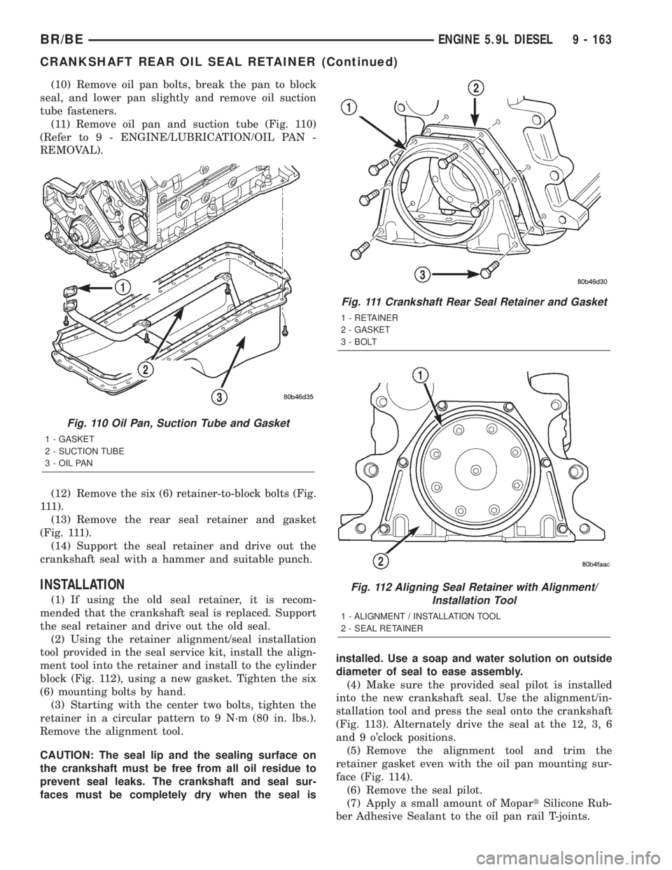
(10) Remove oil pan bolts, break the pan to block
seal, and lower pan slightly and remove oil suction
tube fasteners.
(11) Remove oil pan and suction tube (Fig. 110)
(Refer to 9 - ENGINE/LUBRICATION/OIL PAN -
REMOVAL).
(12) Remove the six (6) retainer-to-block bolts (Fig.
111).
(13) Remove the rear seal retainer and gasket
(Fig. 111).
(14) Support the seal retainer and drive out the
crankshaft seal with a hammer and suitable punch.
INSTALLATION
(1) If using the old seal retainer, it is recom-
mended that the crankshaft seal is replaced. Support
the seal retainer and drive out the old seal.
(2) Using the retainer alignment/seal installation
tool provided in the seal service kit, install the align-
ment tool into the retainer and install to the cylinder
block (Fig. 112), using a new gasket. Tighten the six
(6) mounting bolts by hand.
(3) Starting with the center two bolts, tighten the
retainer in a circular pattern to 9 N´m (80 in. lbs.).
Remove the alignment tool.
CAUTION: The seal lip and the sealing surface on
the crankshaft must be free from all oil residue to
prevent seal leaks. The crankshaft and seal sur-
faces must be completely dry when the seal isinstalled. Use a soap and water solution on outside
diameter of seal to ease assembly.
(4) Make sure the provided seal pilot is installed
into the new crankshaft seal. Use the alignment/in-
stallation tool and press the seal onto the crankshaft
(Fig. 113). Alternately drive the seal at the 12, 3, 6
and 9 o'clock positions.
(5) Remove the alignment tool and trim the
retainer gasket even with the oil pan mounting sur-
face (Fig. 114).
(6) Remove the seal pilot.
(7) Apply a small amount of MopartSilicone Rub-
ber Adhesive Sealant to the oil pan rail T-joints.
Fig. 110 Oil Pan, Suction Tube and Gasket
1 - GASKET
2 - SUCTION TUBE
3 - OIL PAN
Fig. 111 Crankshaft Rear Seal Retainer and Gasket
1 - RETAINER
2 - GASKET
3 - BOLT
Fig. 112 Aligning Seal Retainer with Alignment/
Installation Tool
1 - ALIGNMENT / INSTALLATION TOOL
2 - SEAL RETAINER
BR/BEENGINE 5.9L DIESEL 9 - 163
CRANKSHAFT REAR OIL SEAL RETAINER (Continued)
Page 1263 of 2255
(18) Remove the camshaft (Refer to 9 - ENGINE/
ENGINE BLOCK/CAMSHAFT & BEARINGS (IN
BLOCK) - REMOVAL).
(19) Remove the six front oil pan fasteners.
(20) Remove the gear housing fasteners.
NOTE: Use care when removing the gear housing,
to avoid damage to the oil pan gasket, as the gas-
ket will be reused if it is not damaged.
(21) Slide a feeler gauge between the gear housing
and oil pan gasket, to break the gasket seal.
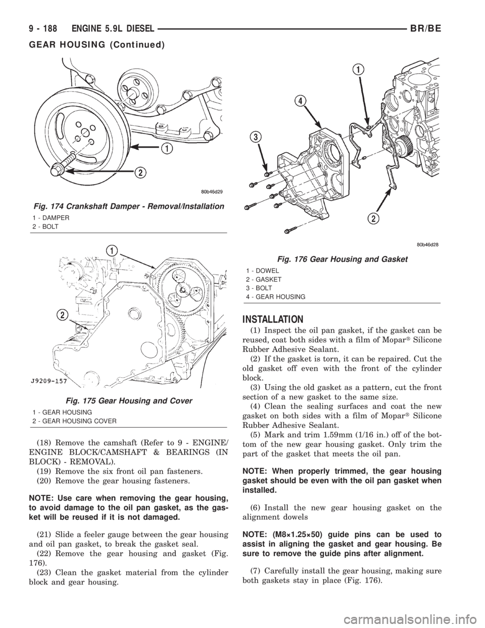
(22) Remove the gear housing and gasket (Fig.
176).
(23) Clean the gasket material from the cylinder
block and gear housing.
INSTALLATION
(1) Inspect the oil pan gasket, if the gasket can be
reused, coat both sides with a film of MopartSilicone
Rubber Adhesive Sealant.
(2) If the gasket is torn, it can be repaired. Cut the
old gasket off even with the front of the cylinder
block.
(3) Using the old gasket as a pattern, cut the front
section of a new gasket to the same size.
(4) Clean the sealing surfaces and coat the new
gasket on both sides with a film of MopartSilicone
Rubber Adhesive Sealant.
(5) Mark and trim 1.59mm (1/16 in.) off of the bot-
tom of the new gear housing gasket. Only trim the
part of the gasket that meets the oil pan.
NOTE: When properly trimmed, the gear housing
gasket should be even with the oil pan gasket when
installed.
(6) Install the new gear housing gasket on the
alignment dowels
NOTE: (M8ý1.25ý50) guide pins can be used to
assist in aligning the gasket and gear housing. Be
sure to remove the guide pins after alignment.
(7) Carefully install the gear housing, making sure
both gaskets stay in place (Fig. 176).
Fig. 174 Crankshaft Damper - Removal/Installation
1 - DAMPER
2 - BOLT
Fig. 175 Gear Housing and Cover
1 - GEAR HOUSING
2 - GEAR HOUSING COVER
Fig. 176 Gear Housing and Gasket
1 - DOWEL
2 - GASKET
3 - BOLT
4 - GEAR HOUSING
9 - 188 ENGINE 5.9L DIESELBR/BE
GEAR HOUSING (Continued)
Page 1454 of 2255
TRANSMISSION AND TRANSFER CASE
TABLE OF CONTENTS
page page
MANUAL - NV4500........................1
MANUAL - NV5600.......................46
AUTOMATIC TRANSMISSION - 46RE.........87AUTOMATIC TRANSMISSION - 47RE........259
TRANSFER CASE - NV241LD..............430
TRANSFER CASE - NV241HD.............465
MANUAL - NV4500
TABLE OF CONTENTS
page page
MANUAL - NV4500
DESCRIPTION..........................1
OPERATION............................3
DIAGNOSIS AND TESTING................3
REMOVAL.............................4
DISASSEMBLY..........................5
CLEANING............................20
INSPECTION..........................20
ASSEMBLY............................21
INSTALLATION.........................37
SPECIFICATIONS.......................38
SPECIAL TOOLS.......................38ADAPTER HOUSING SEAL - NV4500
REMOVAL.............................42
INSTALLATION.........................42
EXTENSION HOUSING SEAL - NV4500
REMOVAL.............................42
INSTALLATION.........................42
SHIFT MECHANISM - NV4500
REMOVAL.............................43
INSTALLATION.........................44
SHIFT COVER - NV4500
REMOVAL.............................45
INSTALLATION.........................45
MANUAL - NV4500
DESCRIPTION
The NV4500 is a five speed constant mesh manual
transmission (Fig. 1). All gear ranges including
reverse are synchronized. Fifth gear is an overdrive
range. The transmission has a cast iron gear case
and aluminum shift cover.
Two versions are used, a standard duty for 5.9L
applications and a heavy duty for V10 and Cummins
diesel applications. Main differences are the larger
diameter input shaft, output shaft and mainshaft
fifth gear in the heavy duty model.
Tapered roller bearings support the drive gear,
mainshaft and countershaft in the gear case. Roller
bearings in the drive gear support the forward end ofthe mainshaft. The mainshaft gears are all supported
on caged type roller bearings. Drive gear thrust reac-
tion is controlled by a needle type thrust bearing.
The bearing is located at the forward end of the
mainshaft.
The transmission is a top loader style. The shift
lever is located in a shifter tower which is bolted to
the shift cover and operates the shift forks and rails
directly. The shift forks and rails are all located
within the aluminum cover which is bolted to the top
of the gear case.
SHIFT PATTERN
The shift pattern is in a modified H pattern (Fig.
2). Overdrive fifth and reverse gears are in line and
outboard of the first through fourth gear positions.
BR/BETRANSMISSION AND TRANSFER CASE 21 - 1
Page 1499 of 2255
MANUAL - NV5600
TABLE OF CONTENTS
page page
MANUAL - NV5600
DESCRIPTION.........................46
OPERATION...........................48
DIAGNOSIS AND TESTING................48
REMOVAL.............................49
DISASSEMBLY.........................49
CLEANING............................63
INSPECTION..........................63
ASSEMBLY............................64
INSTALLATION.........................78
SPECIFICATIONS.......................79SPECIAL TOOLS......................80
ADAPTER HOUSING SEAL - NV5600
REMOVAL.............................85
INSTALLATION.........................85
EXTENSION HOUSING SEAL - NV5600
REMOVAL.............................85
INSTALLATION.........................85
SHIFT COVER - NV5600
REMOVAL.............................86
INSTALLATION.........................86
MANUAL - NV5600
DESCRIPTION
The NV5600 is a six speed constant mesh manual
transmission (Fig. 1). All gear ranges including
reverse are synchronized. First and second gears uti-
lize dual cone synchronizers in order to aid shifting.
Sixth gear is an overdrive range. The transmission
uses cast iron for the gear case and extension/
adapter housing and aluminum for the clutch hous-
ing.
To drain the trans remove the bottom PTO cover
bolt. Fill the trans through the plug to the rear of the
PTO cover (Fig. 1). Dry fill is approximately 4.5 liters
(9.5 pints) or to the bottom edge of the fill plug hole.
The transmission is a end loader transmission. The
shift lever is located in a shifter tower which is
bolted to the gear case and operates the shift shaft.
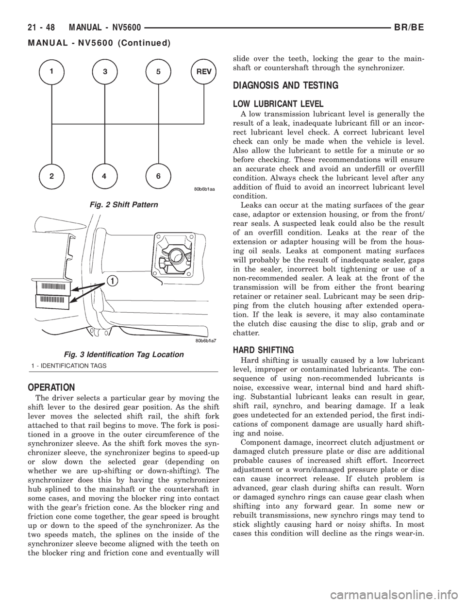
The shift pattern is in a modified H pattern (Fig.
2). Overdrive fifth and sixth gears are in line and
outboard of the first through fourth gear positions.
Reverse gear is to the right of fifth and sixth and for-
ward of the neutral gate.The gear ratios are:
GEAR RATIOS
GEAR RATIO
FIRST 5.63:1
SECOND 3.38:1
THIRD 2.04:1
FOURTH 1.39:1
FIFTH 1.00:1
SIXTH 0.73:1
REVERSE 5.63:1
IDENTIFICATION
The transmission has two identification tags
attached to the driver side upper clutch housing (Fig.
3). One tag provides the transmission part number.
The second tag provides sequencing and build date
information. The information on the tags are essen-
tial to correct parts ordering.
21 - 46 MANUAL - NV5600BR/BE
Page 1501 of 2255
OPERATION
The driver selects a particular gear by moving the
shift lever to the desired gear position. As the shift
lever moves the selected shift rail, the shift fork
attached to that rail begins to move. The fork is posi-
tioned in a groove in the outer circumference of the
synchronizer sleeve. As the shift fork moves the syn-
chronizer sleeve, the synchronizer begins to speed-up
or slow down the selected gear (depending on
whether we are up-shifting or down-shifting). The
synchronizer does this by having the synchronizer
hub splined to the mainshaft or the countershaft in
some cases, and moving the blocker ring into contact
with the gear's friction cone. As the blocker ring and
friction cone come together, the gear speed is brought
up or down to the speed of the synchronizer. As the
two speeds match, the splines on the inside of the
synchronizer sleeve become aligned with the teeth on
the blocker ring and friction cone and eventually willslide over the teeth, locking the gear to the main-
shaft or countershaft through the synchronizer.
DIAGNOSIS AND TESTING
LOW LUBRICANT LEVEL
A low transmission lubricant level is generally the
result of a leak, inadequate lubricant fill or an incor-
rect lubricant level check. A correct lubricant level
check can only be made when the vehicle is level.
Also allow the lubricant to settle for a minute or so
before checking. These recommendations will ensure
an accurate check and avoid an underfill or overfill
condition. Always check the lubricant level after any
addition of fluid to avoid an incorrect lubricant level
condition.
Leaks can occur at the mating surfaces of the gear
case, adaptor or extension housing, or from the front/
rear seals. A suspected leak could also be the result
of an overfill condition. Leaks at the rear of the
extension or adapter housing will be from the hous-
ing oil seals. Leaks at component mating surfaces
will probably be the result of inadequate sealer, gaps
in the sealer, incorrect bolt tightening or use of a
non-recommended sealer. A leak at the front of the
transmission will be from either the front bearing
retainer or retainer seal. Lubricant may be seen drip-
ping from the clutch housing after extended opera-
tion. If the leak is severe, it may also contaminate
the clutch disc causing the disc to slip, grab and or
chatter.
HARD SHIFTING
Hard shifting is usually caused by a low lubricant
level, improper or contaminated lubricants. The con-
sequence of using non-recommended lubricants is
noise, excessive wear, internal bind and hard shift-
ing. Substantial lubricant leaks can result in gear,
shift rail, synchro, and bearing damage. If a leak
goes undetected for an extended period, the first indi-
cations of component damage are usually hard shift-
ing and noise.
Component damage, incorrect clutch adjustment or
damaged clutch pressure plate or disc are additional
probable causes of increased shift effort. Incorrect
adjustment or a worn/damaged pressure plate or disc
can cause incorrect release. If clutch problem is
advanced, gear clash during shifts can result. Worn
or damaged synchro rings can cause gear clash when
shifting into any forward gear. In some new or
rebuilt transmissions, new synchro rings may tend to
stick slightly causing hard or noisy shifts. In most
cases this condition will decline as the rings wear-in.
Fig. 2 Shift Pattern
Fig. 3 Identification Tag Location
1 - IDENTIFICATION TAGS
21 - 48 MANUAL - NV5600BR/BE
MANUAL - NV5600 (Continued)
Page 1582 of 2255
INPUT SHAFT END PLAY CHECK
NOTE: Overdrive unit must be installed in order to
correctly measure the input shaft end-play.
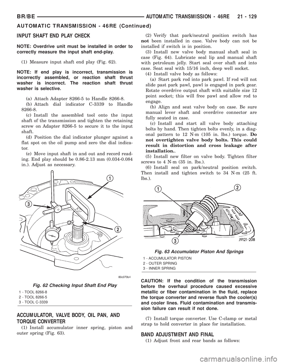
(1) Measure input shaft end play (Fig. 62).
NOTE: If end play is incorrect, transmission is
incorrectly assembled, or reaction shaft thrust
washer is incorrect. The reaction shaft thrust
washer is selective.
(a) Attach Adapter 8266-5 to Handle 8266-8.
(b) Attach dial indicator C-3339 to Handle
8266-8.
(c) Install the assembled tool onto the input
shaft of the transmission and tighten the retaining
screw on Adapter 8266-5 to secure it to the input
shaft.
(d) Position the dial indicator plunger against a
flat spot on the oil pump and zero the dial indica-
tor.
(e) Move input shaft in and out and record read-
ing. End play should be 0.86-2.13 mm (0.034-0.084
in.). Adjust as necessary.
ACCUMULATOR, VALVE BODY, OIL PAN, AND
TORQUE CONVERTER
(1) Install accumulator inner spring, piston and
outer spring (Fig. 63).(2) Verify that park/neutral position switch has
notbeen installed in case. Valve body can not be
installed if switch is in position.
(3) Install new valve body manual shaft seal in
case (Fig. 64). Lubricate seal lip and manual shaft
with petroleum jelly. Start seal over shaft and into
case. Seat seal with 15/16 inch, deep well socket.
(4) Install valve body as follows:
(a) Start park rod into park pawl. If rod will not
slide past park pawl, pawl is engaged in park gear.
Rotate overdrive output shaft with suitable size 12
point socket; this will free pawl and allow rod to
engage.
(b) Align and seat valve body on case. Be sure
manual lever shaft and overdrive connector are
fully seated in case.
(c) Install and start all valve body attaching
bolts by hand. Then tighten bolts evenly, in a diag-
onal pattern to 12 N´m (105 in. lbs.) torque.Do
not overtighten valve body bolts. This could
result in distortion and cross leakage after
installation..
(5) Install new filter on valve body. Tighten filter
screws to 4 N´m (35 in. lbs.).
(6) Install seal on park/neutral position switch.
Then install and tighten switch to 34 N´m (25 ft.
lbs.).
CAUTION: If the condition of the transmission
before the overhaul procedure caused excessive
metallic or fiber contamination in the fluid, replace
the torque converter and reverse flush the cooler(s)
and cooler lines. Fluid contamination and transmis-
sion failure can result if not done.
(7) Install torque converter. Use C-clamp or metal
strap to hold converter in place for installation.
BAND ADJUSTMENT AND FINAL
(1) Adjust front and rear bands as follows:
Fig. 62 Checking Input Shaft End Play
1 - TOOL 8266-8
2 - TOOL 8266-5
3 - TOOL C-3339
Fig. 63 Accumulator Piston And Springs
1 - ACCUMULATOR PISTON
2 - OUTER SPRING
3 - INNER SPRING
BR/BEAUTOMATIC TRANSMISSION - 46RE 21 - 129
AUTOMATIC TRANSMISSION - 46RE (Continued)
Page 1643 of 2255
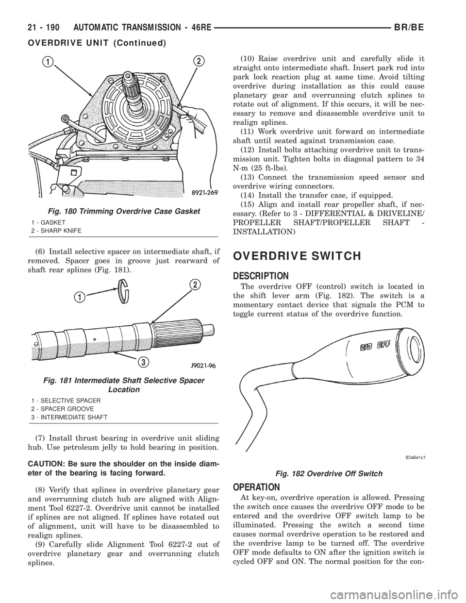
(6) Install selective spacer on intermediate shaft, if
removed. Spacer goes in groove just rearward of
shaft rear splines (Fig. 181).
(7) Install thrust bearing in overdrive unit sliding
hub. Use petroleum jelly to hold bearing in position.
CAUTION: Be sure the shoulder on the inside diam-
eter of the bearing is facing forward.
(8) Verify that splines in overdrive planetary gear
and overrunning clutch hub are aligned with Align-
ment Tool 6227-2. Overdrive unit cannot be installed
if splines are not aligned. If splines have rotated out
of alignment, unit will have to be disassembled to
realign splines.
(9) Carefully slide Alignment Tool 6227-2 out of
overdrive planetary gear and overrunning clutch
splines.(10) Raise overdrive unit and carefully slide it
straight onto intermediate shaft. Insert park rod into
park lock reaction plug at same time. Avoid tilting
overdrive during installation as this could cause
planetary gear and overrunning clutch splines to
rotate out of alignment. If this occurs, it will be nec-
essary to remove and disassemble overdrive unit to
realign splines.
(11) Work overdrive unit forward on intermediate
shaft until seated against transmission case.
(12) Install bolts attaching overdrive unit to trans-
mission unit. Tighten bolts in diagonal pattern to 34
N´m (25 ft-lbs).
(13) Connect the transmission speed sensor and
overdrive wiring connectors.
(14) Install the transfer case, if equipped.
(15) Align and install rear propeller shaft, if nec-
essary. (Refer to 3 - DIFFERENTIAL & DRIVELINE/
PROPELLER SHAFT/PROPELLER SHAFT -
INSTALLATION)OVERDRIVE SWITCH
DESCRIPTION
The overdrive OFF (control) switch is located in
the shift lever arm (Fig. 182). The switch is a
momentary contact device that signals the PCM to
toggle current status of the overdrive function.
OPERATION
At key-on, overdrive operation is allowed. Pressing
the switch once causes the overdrive OFF mode to be
entered and the overdrive OFF switch lamp to be
illuminated. Pressing the switch a second time
causes normal overdrive operation to be restored and
the overdrive lamp to be turned off. The overdrive
OFF mode defaults to ON after the ignition switch is
cycled OFF and ON. The normal position for the con-
Fig. 180 Trimming Overdrive Case Gasket
1 - GASKET
2 - SHARP KNIFE
Fig. 181 Intermediate Shaft Selective Spacer
Location
1 - SELECTIVE SPACER
2 - SPACER GROOVE
3 - INTERMEDIATE SHAFT
Fig. 182 Overdrive Off Switch
21 - 190 AUTOMATIC TRANSMISSION - 46REBR/BE
OVERDRIVE UNIT (Continued)
Page 1753 of 2255
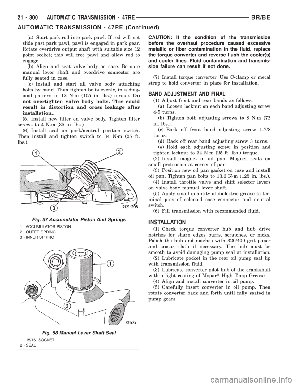
(a) Start park rod into park pawl. If rod will not
slide past park pawl, pawl is engaged in park gear.
Rotate overdrive output shaft with suitable size 12
point socket; this will free pawl and allow rod to
engage.
(b) Align and seat valve body on case. Be sure
manual lever shaft and overdrive connector are
fully seated in case.
(c) Install and start all valve body attaching
bolts by hand. Then tighten bolts evenly, in a diag-
onal pattern to 12 N´m (105 in. lbs.) torque.Do
not overtighten valve body bolts. This could
result in distortion and cross leakage after
installation..
(5) Install new filter on valve body. Tighten filter
screws to 4 N´m (35 in. lbs.).
(6) Install seal on park/neutral position switch.
Then install and tighten switch to 34 N´m (25 ft.
lbs.).CAUTION: If the condition of the transmission
before the overhaul procedure caused excessive
metallic or fiber contamination in the fluid, replace
the torque converter and reverse flush the cooler(s)
and cooler lines. Fluid contamination and transmis-
sion failure can result if not done.
(7) Install torque converter. Use C-clamp or metal
strap to hold converter in place for installation.
BAND ADJUSTMENT AND FINAL
(1) Adjust front and rear bands as follows:
(a) Loosen locknut on each band adjusting screw
4-5 turns.
(b) Tighten both adjusting screws to 8 N´m (72
in. lbs.).
(c) Back off front band adjusting screw 1-7/8
turns.
(d) Back off rear band adjusting screw 3 turns.
(e) Hold each adjusting screw in position and
tighten locknut to 34 N´m (25 ft. lbs.) torque.
(2) Install magnet in oil pan. Magnet seats on
small protrusion at corner of pan.
(3) Position new oil pan gasket on case and install
oil pan. Tighten pan bolts to 13.6 N´m (125 in. lbs.).
(4) Install throttle valve and shift selector levers
on valve body manual lever shaft.
(5) Apply small quantity of dielectric grease to ter-
minal pins of solenoid case connector and neutral
switch.
(6) Fill transmission with recommended fluid.
INSTALLATION
(1) Check torque converter hub and hub drive
notches for sharp edges burrs, scratches, or nicks.
Polish the hub and notches with 320/400 grit paper
and crocus cloth if necessary. The hub must be
smooth to avoid damaging pump seal at installation.
(2) Lubricate pocket in the rear oil pump seal lip
with transmission fluid.
(3) Lubricate converter pilot hub of the crankshaft
with a light coating of MopartHigh Temp Grease.
(4) Align and install converter in oil pump.
(5) Carefully insert converter in oil pump. Then
rotate converter back and forth until fully seated in
pump gears.
Fig. 57 Accumulator Piston And Springs
1 - ACCUMULATOR PISTON
2 - OUTER SPRING
3 - INNER SPRING
Fig. 58 Manual Lever Shaft Seal
1 - 15/16©© SOCKET
2 - SEAL
21 - 300 AUTOMATIC TRANSMISSION - 47REBR/BE
AUTOMATIC TRANSMISSION - 47RE (Continued)
Page 1816 of 2255
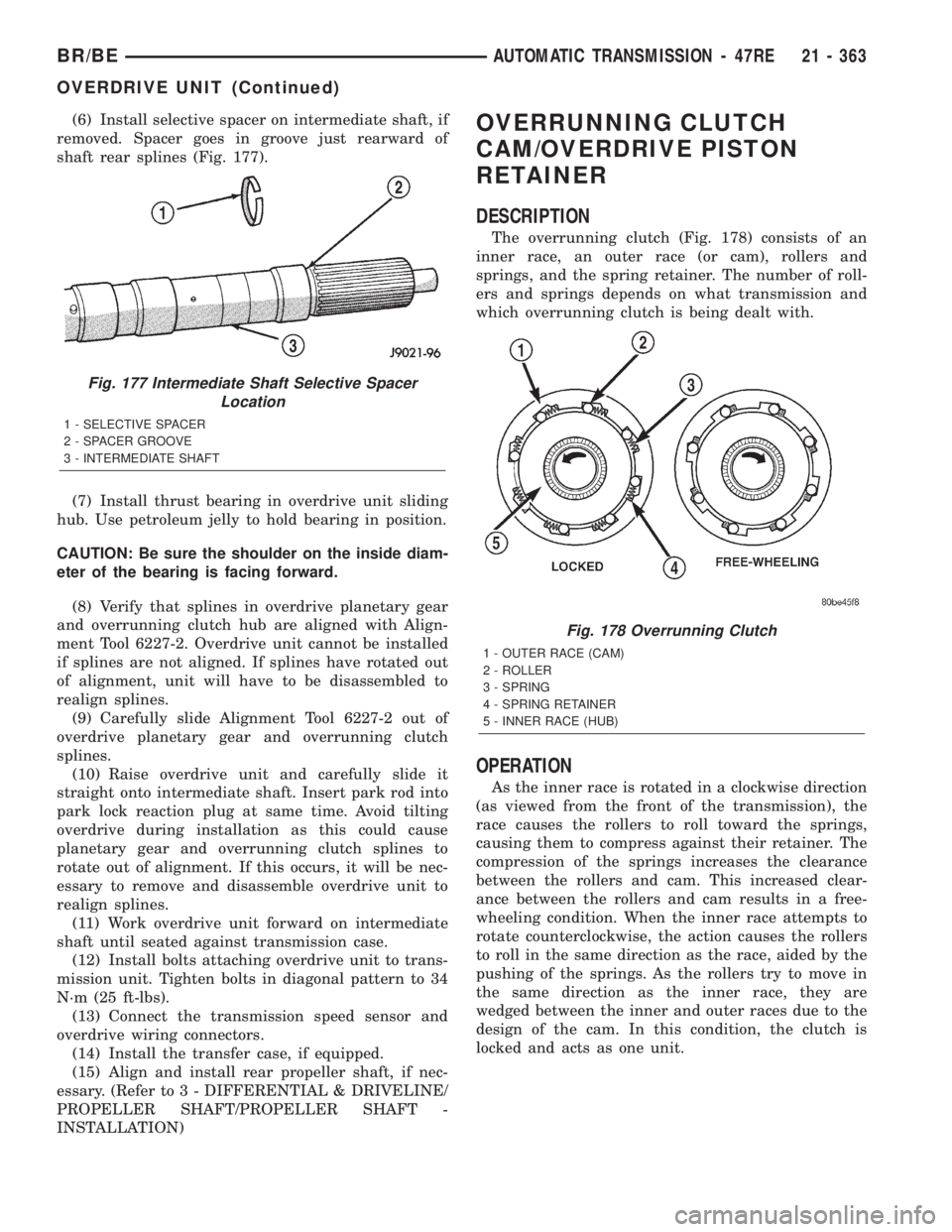
(6) Install selective spacer on intermediate shaft, if
removed. Spacer goes in groove just rearward of
shaft rear splines (Fig. 177).
(7) Install thrust bearing in overdrive unit sliding
hub. Use petroleum jelly to hold bearing in position.
CAUTION: Be sure the shoulder on the inside diam-
eter of the bearing is facing forward.
(8) Verify that splines in overdrive planetary gear
and overrunning clutch hub are aligned with Align-
ment Tool 6227-2. Overdrive unit cannot be installed
if splines are not aligned. If splines have rotated out
of alignment, unit will have to be disassembled to
realign splines.
(9) Carefully slide Alignment Tool 6227-2 out of
overdrive planetary gear and overrunning clutch
splines.
(10) Raise overdrive unit and carefully slide it
straight onto intermediate shaft. Insert park rod into
park lock reaction plug at same time. Avoid tilting
overdrive during installation as this could cause
planetary gear and overrunning clutch splines to
rotate out of alignment. If this occurs, it will be nec-
essary to remove and disassemble overdrive unit to
realign splines.
(11) Work overdrive unit forward on intermediate
shaft until seated against transmission case.
(12) Install bolts attaching overdrive unit to trans-
mission unit. Tighten bolts in diagonal pattern to 34
N´m (25 ft-lbs).
(13) Connect the transmission speed sensor and
overdrive wiring connectors.
(14) Install the transfer case, if equipped.
(15) Align and install rear propeller shaft, if nec-
essary. (Refer to 3 - DIFFERENTIAL & DRIVELINE/
PROPELLER SHAFT/PROPELLER SHAFT -
INSTALLATION)OVERRUNNING CLUTCH
CAM/OVERDRIVE PISTON
RETAINER
DESCRIPTION
The overrunning clutch (Fig. 178) consists of an
inner race, an outer race (or cam), rollers and
springs, and the spring retainer. The number of roll-
ers and springs depends on what transmission and
which overrunning clutch is being dealt with.
OPERATION
As the inner race is rotated in a clockwise direction
(as viewed from the front of the transmission), the
race causes the rollers to roll toward the springs,
causing them to compress against their retainer. The
compression of the springs increases the clearance
between the rollers and cam. This increased clear-
ance between the rollers and cam results in a free-
wheeling condition. When the inner race attempts to
rotate counterclockwise, the action causes the rollers
to roll in the same direction as the race, aided by the
pushing of the springs. As the rollers try to move in
the same direction as the inner race, they are
wedged between the inner and outer races due to the
design of the cam. In this condition, the clutch is
locked and acts as one unit.
Fig. 177 Intermediate Shaft Selective Spacer
Location
1 - SELECTIVE SPACER
2 - SPACER GROOVE
3 - INTERMEDIATE SHAFT
Fig. 178 Overrunning Clutch
1 - OUTER RACE (CAM)
2 - ROLLER
3 - SPRING
4 - SPRING RETAINER
5 - INNER RACE (HUB)
BR/BEAUTOMATIC TRANSMISSION - 47RE 21 - 363
OVERDRIVE UNIT (Continued)
Page 1966 of 2255
DIAGNOSIS AND TESTING
WHEEL INSPECTION
Inspect wheels for:
²Excessive run out
²Dents or cracks
²Damaged wheel lug nut holes
²Air Leaks from any area or surface of the rim
NOTE: Do not attempt to repair a wheel by hammer-
ing, heating or welding.
If a wheel is damaged an original equipment
replacement wheel should be used. When obtaining
replacement wheels, they should be equivalent in
load carrying capacity. The diameter, width, offset,
pilot hole and bolt circle of the wheel should be the
same as the original wheel.
WARNING: FAILURE TO USE EQUIVALENT REPLACE-
MENT WHEELS MAY ADVERSELY AFFECT THE
SAFETY AND HANDLING OF THE VEHICLE. USED
WHEELS ARE NOT RECOMMENDED. THE SERVICE
HISTORY OF THE WHEEL MAY HAVE INCLUDED
SEVERE TREATMENT OR VERY HIGH MILEAGE. THE
RIM COULD FAIL WITHOUT WARNING.
STANDARD PROCEDURE - DUAL REAR WHEEL
INSTALLATION
Dual rear wheels use a special heavy duty lug nut
wrench. It is recommended to remove and install dual
rear wheels only when the proper wrench is available.
The wrench is also use to remove wheel center caps for
more information refer to Owner's Manual.
The tires on both wheels must be completely raised
off the ground when tightening the lug nuts. This
will ensure correct wheel centering and maximum
wheel clamping.
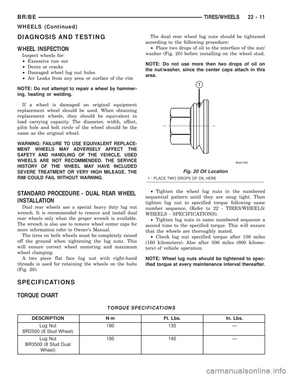
A two piece flat face lug nut with right-hand
threads is used for retaining the wheels on the hubs
(Fig. 20).The dual rear wheel lug nuts should be tightened
according to the following procedure:
²Place two drops of oil to the interface of the nut/
washer (Fig. 20) before installing on the wheel stud.
NOTE: Do not use more then two drops of oil on
the nut/washer, since the center caps attach in this
area.
²Tighten the wheel lug nuts in the numbered
sequential pattern until they are snug tight. Then
tighten lug nut to specified torque following same
number sequence, (Refer to 22 - TIRES/WHEELS/
WHEELS - SPECIFICATIONS).
²Tighten lug nuts in same numbered sequence a
second time to the specified torque. This will ensure
that the wheels are thoroughly mated.
²Check lug nut specified torque after 100 miles
(160 kilometers). Also after 500 miles (800 kilome-
ters) of vehicle operation.
NOTE: Wheel lug nuts should be tightened to spec-
ified torque at every maintenance interval thereafter.
SPECIFICATIONS
TORQUE CHART
TORQUE SPECIFICATIONS
DESCRIPTION N´m Ft. Lbs. In. Lbs.
Lug Nut
BR2500 (8 Stud Wheel)180 135 Ð
Lug Nut
BR3500 (8 Stud Dual
Wheel)195 145 Ð
Fig. 20 Oil Location
1 - PLACE TWO DROPS OF OIL HERE
BR/BETIRES/WHEELS 22 - 11
WHEELS (Continued)