set clock DODGE RAM 2002 Service Repair Manual
[x] Cancel search | Manufacturer: DODGE, Model Year: 2002, Model line: RAM, Model: DODGE RAM 2002Pages: 2255, PDF Size: 62.07 MB
Page 241 of 2255
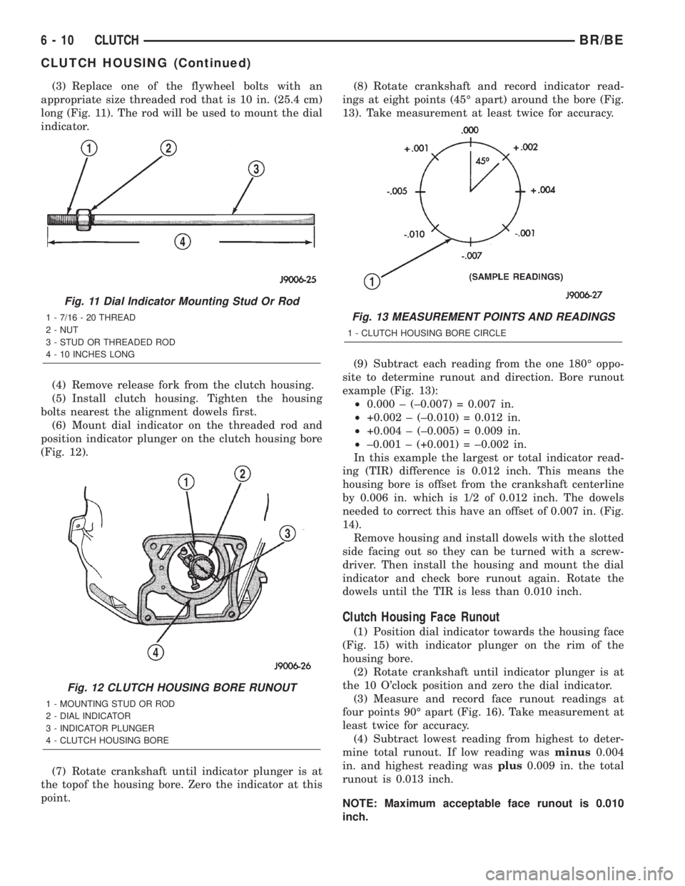
(3) Replace one of the flywheel bolts with an
appropriate size threaded rod that is 10 in. (25.4 cm)
long (Fig. 11). The rod will be used to mount the dial
indicator.
(4) Remove release fork from the clutch housing.
(5) Install clutch housing. Tighten the housing
bolts nearest the alignment dowels first.
(6) Mount dial indicator on the threaded rod and
position indicator plunger on the clutch housing bore
(Fig. 12).
(7) Rotate crankshaft until indicator plunger is at
the topof the housing bore. Zero the indicator at this
point.(8) Rotate crankshaft and record indicator read-
ings at eight points (45É apart) around the bore (Fig.
13). Take measurement at least twice for accuracy.
(9) Subtract each reading from the one 180É oppo-
site to determine runout and direction. Bore runout
example (Fig. 13):
²0.000 ± (±0.007) = 0.007 in.
²+0.002 ± (±0.010) = 0.012 in.
²+0.004 ± (±0.005) = 0.009 in.
²±0.001 ± (+0.001) = ±0.002 in.
In this example the largest or total indicator read-
ing (TIR) difference is 0.012 inch. This means the
housing bore is offset from the crankshaft centerline
by 0.006 in. which is 1/2 of 0.012 inch. The dowels
needed to correct this have an offset of 0.007 in. (Fig.
14).
Remove housing and install dowels with the slotted
side facing out so they can be turned with a screw-
driver. Then install the housing and mount the dial
indicator and check bore runout again. Rotate the
dowels until the TIR is less than 0.010 inch.
Clutch Housing Face Runout
(1) Position dial indicator towards the housing face
(Fig. 15) with indicator plunger on the rim of the
housing bore.
(2) Rotate crankshaft until indicator plunger is at
the 10 O'clock position and zero the dial indicator.
(3) Measure and record face runout readings at
four points 90É apart (Fig. 16). Take measurement at
least twice for accuracy.
(4) Subtract lowest reading from highest to deter-
mine total runout. If low reading wasminus0.004
in. and highest reading wasplus0.009 in. the total
runout is 0.013 inch.
NOTE: Maximum acceptable face runout is 0.010
inch.
Fig. 11 Dial Indicator Mounting Stud Or Rod
1 - 7/16 - 20 THREAD
2 - NUT
3 - STUD OR THREADED ROD
4 - 10 INCHES LONG
Fig. 12 CLUTCH HOUSING BORE RUNOUT
1 - MOUNTING STUD OR ROD
2 - DIAL INDICATOR
3 - INDICATOR PLUNGER
4 - CLUTCH HOUSING BORE
Fig. 13 MEASUREMENT POINTS AND READINGS
1 - CLUTCH HOUSING BORE CIRCLE
6 - 10 CLUTCHBR/BE
CLUTCH HOUSING (Continued)
Page 290 of 2255
INSTALLATION
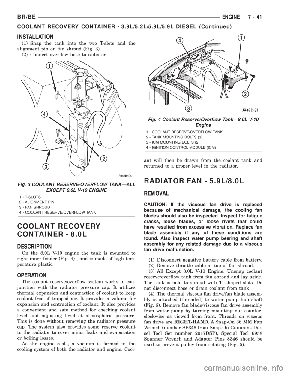
(1) Snap the tank into the two T-slots and the
alignment pin on fan shroud (Fig. 3).
(2) Connect overflow hose to radiator.
COOLANT RECOVERY
CONTAINER - 8.0L
DESCRIPTION
On the 8.0L V-10 engine the tank is mounted to
right inner fender (Fig. 4) , and is made of high tem-
perature plastic.
OPERATION
The coolant reserve/overflow system works in con-
junction with the radiator pressure cap. It utilizes
thermal expansion and contraction of coolant to keep
coolant free of trapped air. It provides a volume for
expansion and contraction of coolant. It also provides
a convenient and safe method for checking coolant
level and adjusting level at atmospheric pressure.
This is done without removing the radiator pressure
cap. The system also provides some reserve coolant
to the radiator to cover minor leaks and evaporation
or boiling losses.
As the engine cools, a vacuum is formed in the
cooling system of both the radiator and engine. Cool-ant will then be drawn from the coolant tank and
returned to a proper level in the radiator.
RADIATOR FAN - 5.9L/8.0L
REMOVAL
CAUTION: If the viscous fan drive is replaced
because of mechanical damage, the cooling fan
blades should also be inspected. Inspect for fatigue
cracks, loose blades, or loose rivets that could
have resulted from excessive vibration. Replace fan
blade assembly if any of these conditions are
found. Also inspect water pump bearing and shaft
assembly for any related damage due to a viscous
fan drive malfunction.
(1) Disconnect negative battery cable from battery.
(2) Remove throttle cable at top of fan shroud.
(3) All Except 8.0L V-10 Engine: Unsnap coolant
reserve/overflow tank from fan shroud and lay aside.
The tank is held to shroud with T- shaped slots. Do
not disconnect hose or drain coolant from tank.
(4) The thermal viscous fan drive/fan blade assem-
bly is attached (threaded) to water pump hub shaft
(Fig. 6). Remove fan blade/viscous fan drive assembly
from water pump by turning mounting nut counter-
clockwise as viewed from front. Threads on viscous
fan drive areRIGHT-HAND.A Snap-On 36 MM Fan
Wrench (number SP346 from Snap-On Cummins Die-
sel Tool Set number 2017DSP), Special Tool 6958
Spanner Wrench and Adapter Pins 8346 should be
used to prevent pulley from rotating (Fig. 5).
Fig. 3 COOLANT RESERVE/OVERFLOW TANKÐALL
EXCEPT 8.0L V-10 ENGINE
1 - T-SLOTS
2 - ALIGNMENT PIN
3 - FAN SHROUD
4 - COOLANT RESERVE/OVERFLOW TANK
Fig. 4 Coolant Reserve/Overflow TankÐ8.0L V-10
Engine
1 - COOLANT RESERVE/OVERFLOW TANK
2 - TANK MOUNTING BOLTS (3)
3 - ICM MOUNTING BOLTS (2)
4 - IGNITION CONTROL MODULE (ICM)
BR/BEENGINE 7 - 41
COOLANT RECOVERY CONTAINER - 3.9L/5.2L/5.9L/5.9L DIESEL (Continued)
Page 292 of 2255
(4) Install fan blade/viscous fan drive assembly to
water pump shaft (Fig. 6).
(5) Except 8.0L V-10 Engine: Install coolant
reserve/overflow tank to fan shroud. Snaps into posi-
tion.
(6) Install throttle cable to fan shroud.
(7) Connect negative battery cable.
NOTE:
Viscous Fan Drive Fluid Pump Out Requirement:
After installing a new viscous fan drive, bring the
engine speed up to approximately 2000 rpm and
hold for approximately two minutes. This will
ensure proper fluid distribution within the drive.
RADIATOR FAN - 5.9L DIESEL
REMOVAL
CAUTION: If the viscous fan drive is replaced
because of mechanical damage, the cooling fan
blades should also be inspected. Inspect for fatigue
cracks, loose blades, or loose rivets that could
have resulted from excessive vibration. Replace fan
blade assembly if any of these conditions are
found. Also inspect water pump bearing and shaft
assembly for any related damage due to a viscous
fan drive malfunction.
(1) Disconnect the battery negative cables.
(2) Remove the fan shroud mounting bolts. Posi-
tion fan shroud towards engine.
CAUTION: Do not remove the fan pulley bolts. This
pulley is under spring tension.
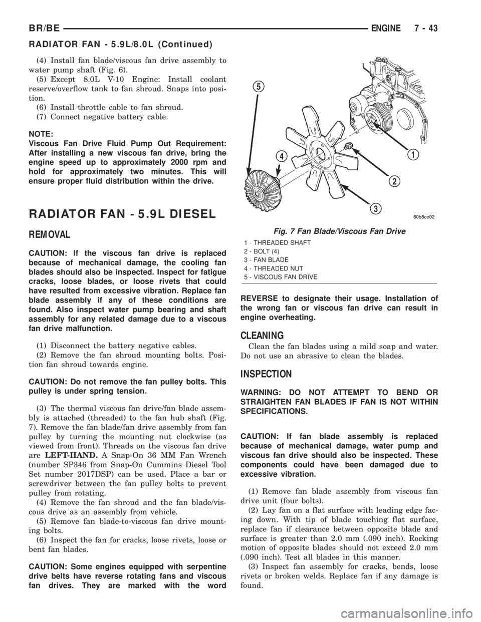
(3) The thermal viscous fan drive/fan blade assem-
bly is attached (threaded) to the fan hub shaft (Fig.
7). Remove the fan blade/fan drive assembly from fan
pulley by turning the mounting nut clockwise (as
viewed from front). Threads on the viscous fan drive
areLEFT-HAND.A Snap-On 36 MM Fan Wrench
(number SP346 from Snap-On Cummins Diesel Tool
Set number 2017DSP) can be used. Place a bar or
screwdriver between the fan pulley bolts to prevent
pulley from rotating.
(4) Remove the fan shroud and the fan blade/vis-
cous drive as an assembly from vehicle.
(5) Remove fan blade-to-viscous fan drive mount-
ing bolts.
(6) Inspect the fan for cracks, loose rivets, loose or
bent fan blades.
CAUTION: Some engines equipped with serpentine
drive belts have reverse rotating fans and viscous
fan drives. They are marked with the wordREVERSE to designate their usage. Installation of
the wrong fan or viscous fan drive can result in
engine overheating.
CLEANING
Clean the fan blades using a mild soap and water.
Do not use an abrasive to clean the blades.
INSPECTION
WARNING: DO NOT ATTEMPT TO BEND OR
STRAIGHTEN FAN BLADES IF FAN IS NOT WITHIN
SPECIFICATIONS.
CAUTION: If fan blade assembly is replaced
because of mechanical damage, water pump and
viscous fan drive should also be inspected. These
components could have been damaged due to
excessive vibration.
(1) Remove fan blade assembly from viscous fan
drive unit (four bolts).
(2) Lay fan on a flat surface with leading edge fac-
ing down. With tip of blade touching flat surface,
replace fan if clearance between opposite blade and
surface is greater than 2.0 mm (.090 inch). Rocking
motion of opposite blades should not exceed 2.0 mm
(.090 inch). Test all blades in this manner.
(3) Inspect fan assembly for cracks, bends, loose
rivets or broken welds. Replace fan if any damage is
found.
Fig. 7 Fan Blade/Viscous Fan Drive
1 - THREADED SHAFT
2 - BOLT (4)
3 - FAN BLADE
4 - THREADED NUT
5 - VISCOUS FAN DRIVE
BR/BEENGINE 7 - 43
RADIATOR FAN - 5.9L/8.0L (Continued)
Page 316 of 2255
(3) Remove windshield washer reservoir tank from
radiator fan shroud.
(4) Disconnect the coolant reserve/overflow tank-
to-radiator hose at the tank.
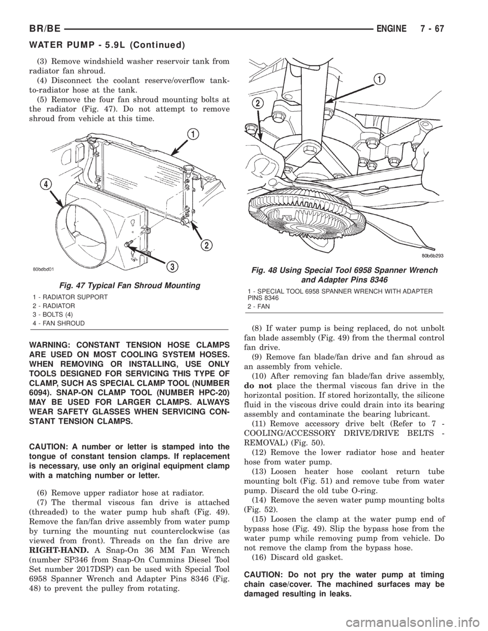
(5) Remove the four fan shroud mounting bolts at
the radiator (Fig. 47). Do not attempt to remove
shroud from vehicle at this time.
WARNING: CONSTANT TENSION HOSE CLAMPS
ARE USED ON MOST COOLING SYSTEM HOSES.
WHEN REMOVING OR INSTALLING, USE ONLY
TOOLS DESIGNED FOR SERVICING THIS TYPE OF
CLAMP, SUCH AS SPECIAL CLAMP TOOL (NUMBER
6094). SNAP-ON CLAMP TOOL (NUMBER HPC-20)
MAY BE USED FOR LARGER CLAMPS. ALWAYS
WEAR SAFETY GLASSES WHEN SERVICING CON-
STANT TENSION CLAMPS.
CAUTION: A number or letter is stamped into the
tongue of constant tension clamps. If replacement
is necessary, use only an original equipment clamp
with a matching number or letter.
(6) Remove upper radiator hose at radiator.
(7) The thermal viscous fan drive is attached
(threaded) to the water pump hub shaft (Fig. 49).
Remove the fan/fan drive assembly from water pump
by turning the mounting nut counterclockwise (as
viewed from front). Threads on the fan drive are
RIGHT-HAND.A Snap-On 36 MM Fan Wrench
(number SP346 from Snap-On Cummins Diesel Tool
Set number 2017DSP) can be used with Special Tool
6958 Spanner Wrench and Adapter Pins 8346 (Fig.
48) to prevent the pulley from rotating.(8) If water pump is being replaced, do not unbolt
fan blade assembly (Fig. 49) from the thermal control
fan drive.
(9) Remove fan blade/fan drive and fan shroud as
an assembly from vehicle.
(10) After removing fan blade/fan drive assembly,
do notplace the thermal viscous fan drive in the
horizontal position. If stored horizontally, the silicone
fluid in the viscous drive could drain into its bearing
assembly and contaminate the bearing lubricant.
(11) Remove accessory drive belt (Refer to 7 -
COOLING/ACCESSORY DRIVE/DRIVE BELTS -
REMOVAL) (Fig. 50).
(12) Remove the lower radiator hose and heater
hose from water pump.
(13) Loosen heater hose coolant return tube
mounting bolt (Fig. 51) and remove tube from water
pump. Discard the old tube O-ring.
(14) Remove the seven water pump mounting bolts
(Fig. 52).
(15) Loosen the clamp at the water pump end of
bypass hose (Fig. 49). Slip the bypass hose from the
water pump while removing pump from vehicle. Do
not remove the clamp from the bypass hose.
(16) Discard old gasket.
CAUTION: Do not pry the water pump at timing
chain case/cover. The machined surfaces may be
damaged resulting in leaks.
Fig. 47 Typical Fan Shroud Mounting
1 - RADIATOR SUPPORT
2 - RADIATOR
3 - BOLTS (4)
4 - FAN SHROUD
Fig. 48 Using Special Tool 6958 Spanner Wrench
and Adapter Pins 8346
1 - SPECIAL TOOL 6958 SPANNER WRENCH WITH ADAPTER
PINS 8346
2-FAN
BR/BEENGINE 7 - 67
WATER PUMP - 5.9L (Continued)
Page 319 of 2255
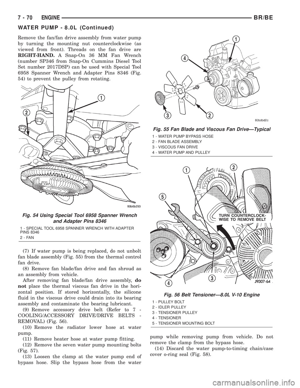
Remove the fan/fan drive assembly from water pump
by turning the mounting nut counterclockwise (as
viewed from front). Threads on the fan drive are
RIGHT-HAND.A Snap-On 36 MM Fan Wrench
(number SP346 from Snap-On Cummins Diesel Tool
Set number 2017DSP) can be used with Special Tool
6958 Spanner Wrench and Adapter Pins 8346 (Fig.
54) to prevent the pulley from rotating.
(7) If water pump is being replaced, do not unbolt
fan blade assembly (Fig. 55) from the thermal control
fan drive.
(8) Remove fan blade/fan drive and fan shroud as
an assembly from vehicle.
After removing fan blade/fan drive assembly,do
notplace the thermal viscous fan drive in the hori-
zontal position. If stored horizontally, the silicone
fluid in the viscous drive could drain into its bearing
assembly and contaminate the bearing lubricant.
(9) Remove accessory drive belt (Refer to 7 -
COOLING/ACCESSORY DRIVE/DRIVE BELTS -
REMOVAL) (Fig. 56).
(10) Remove the radiator lower hose at water
pump.
(11) Remove heater hose at water pump fitting.
(12) Remove the seven water pump mounting bolts
(Fig. 57).
(13) Loosen the clamp at the water pump end of
bypass hose. Slip the bypass hose from the waterpump while removing pump from vehicle. Do not
remove the clamp from the bypass hose.
(14) Discard the water pump-to-timing chain/case
cover o-ring seal (Fig. 58).
Fig. 54 Using Special Tool 6958 Spanner Wrench
and Adapter Pins 8346
1 - SPECIAL TOOL 6958 SPANNER WRENCH WITH ADAPTER
PINS 8346
2-FAN
Fig. 55 Fan Blade and Viscous Fan DriveÐTypical
1 - WATER PUMP BYPASS HOSE
2 - FAN BLADE ASSEMBLY
3 - VISCOUS FAN DRIVE
4 - WATER PUMP AND PULLEY
Fig. 56 Belt TensionerÐ8.0L V-10 Engine
1 - PULLEY BOLT
2 - IDLER PULLEY
3 - TENSIONER PULLEY
4 - TENSIONER
5 - TENSIONER MOUNTING BOLT
7 - 70 ENGINEBR/BE
WATER PUMP - 8.0L (Continued)
Page 338 of 2255
AUDIO
TABLE OF CONTENTS
page page
AUDIO
DESCRIPTION..........................1
OPERATION............................2
DIAGNOSIS AND TESTING - AUDIO..........2
SPECIAL TOOLS
AUDIO SYSTEMS......................4
ANTENNA BODY & CABLE
DESCRIPTION..........................4
OPERATION............................4
DIAGNOSIS AND TESTING - ANTENNA.......5
REMOVAL.............................6
INSTALLATION..........................6
RADIO CHOKE RELAY
DESCRIPTION..........................7
OPERATION............................8
DIAGNOSIS AND TESTING - RADIO CHOKE
RELAY...............................8
REMOVAL.............................8
INSTALLATION..........................9
INSTRUMENT PANEL ANTENNA CABLE
REMOVAL.............................9
INSTALLATION..........................9
RADIO
DESCRIPTION.........................10
OPERATION...........................10
DIAGNOSIS AND TESTING - RADIO.........10
REMOVAL.............................11
INSTALLATION.........................11
RADIO NOISE SUPPRESSION COMPONENTS
DESCRIPTION.........................12
DIAGNOSIS AND TESTING - RADIO NOISE
SUPPRESSION COMPONENTS...........12ENGINE-TO-BODY GROUND STRAP
REMOVAL.............................12
INSTALLATION.........................13
CAB-TO- BED GROUND STRAP
REMOVAL.............................13
INSTALLATION.........................14
HEATER CORE GROUND STRAP
REMOVAL.............................14
INSTALLATION.........................14
REMOTE SWITCHES
DESCRIPTION.........................14
OPERATION...........................15
DIAGNOSIS AND TESTING - REMOTE
SWITCHES..........................15
REMOVAL.............................16
INSTALLATION.........................16
SPEAKER
DESCRIPTION.........................17
OPERATION...........................17
DIAGNOSIS AND TESTING - SPEAKER......17
A-PILLAR TWEETER SPEAKER
REMOVAL.............................18
INSTALLATION.........................19
FRONT DOOR SPEAKER
REMOVAL.............................19
INSTALLATION.........................19
REAR CAB SIDE PANEL SPEAKER
REMOVAL.............................20
INSTALLATION.........................20
REAR DOOR SPEAKER
REMOVAL.............................20
INSTALLATION.........................21
AUDIO
DESCRIPTION
An audio system is standard factory-installed
equipment on this model, unless the vehicle is
ordered with an available radio delete option. The
standard equipment audio system includes an
AM/FM/cassette (RAS sales code) receiver, and
speakers in four locations. Several combinations of
radio receivers and speaker systems are offered as
optional equipment on this model. The audio system
uses an ignition switched source of battery current so
that the system will only operate when the ignition
switch is in the On or Accessory positions. The audio
system includes the following components:²Antenna
²Clockspring (with remote radio switches only)
²Filter, choke and speaker relay (with premium
speaker system only)
²High-line or premium Central Timer Module
(CTM) (with remote radio switches)
²Radio noise suppression components
²Radio receiver
²Remote radio switches (optional with RAZ radio
receiver only)
²Speakers
Refer to Electrical, Restraints for more information
on the clockspring. Refer to Electrical, Body Control/
Central Control Module for more information on the
Central Timer Module. Refer to the appropriate wir-
ing information. The wiring information includes wir-
BR/BEAUDIO 8A - 1
Page 340 of 2255
Audio System Diagnosis
CONDITION POSSIBLE CAUSE CORRECTION
NO DISPLAY 1. Fuse faulty. 1. Check radio fuses in junction block. Replace faulty
fuses, if required.
2. Radio connector faulty. 2. Check for loose or corroded radio connections. Repair,
if required.
3. Wiring faulty. 3. Check for battery voltage at radio connector. Repair
wiring, if required.
4. Ground faulty. 4. Check for continuity between radio chassis and a
known good ground. There should be continuity. Repair
ground, if required.
5. Radio faulty. 5. Refer to Radio in the Diagnosis and Testing section of
this group.
CLOCK WILL NOT KEEP
SET TIME1. Fuse faulty. 1. Check ignition-off draw fuse. Replace faulty fuse, if
required.
2. Radio connector faulty. 2. Check for loose or corroded radio connections. Repair,
if required.
3. Wiring faulty. 3. Check for battery voltage at radio connector. Repair
wiring, if required.
4. Ground faulty. 4. Check for continuity between radio chassis and a
known good ground. There should be continuity. Repair
ground, if required.
5. Radio faulty. 5. Refer to Radio in the Diagnosis and Testing section of
this group.
POOR RADIO
RECEPTION1. Antenna faulty. 1. Refer to Antenna in the Diagnosis and Testing section
of this group.
2. Ground faulty. 2. Check for continuity between radio chassis and a
known good ground. There should be continuity. Repair
ground, if required.
3. Radio faulty. 3. Refer to Radio in the Diagnosis and Testing section of
this group.
4. Faulty EMI or RFI
noise suppression.4. Refer to Radio Frequency Interference in the Diagnosis
and Testing section of this group.
NO/POOR TAPE
OPERATION1. Faulty tape. 1. Insert known good tape and test operation.
2. Foreign objects behind
tape door.2. Remove foreign objects and test operation.
3. Dirty cassette tape
head.3. Clean head with Mopar Cassette Head Cleaner.
4. Faulty tape deck. 4. Exchange or replace radio, if required.
NO COMPACT DISC
OPERATION1. Faulty CD. 1. Insert known good CD and test operation.
2. Foreign material on
CD.2. Clean CD and test operation.
3. Condensation on CD
or optics.3. Allow temperature of vehicle interior to stabilize and
test operation.
4. Faulty CD player. 4. Exchange or replace radio, if required.
BR/BEAUDIO 8A - 3
AUDIO (Continued)
Page 347 of 2255
RADIO
DESCRIPTION
Available factory-installed radio receivers for this
model include an AM/FM/cassette (RAS sales code),
an AM/FM/CD/3-band graphic equalizer (RBR sales
code), or an AM/FM/CD/cassette/3-band graphic
equalizer (RAZ sales code). The factory-installed RAZ
sales code radio receivers can also communicate on
the Chrysler Collision Detection (CCD) data bus net-
work through a separate two-way wire harness con-
nector. All factory-installed receivers are stereo
Electronically Tuned Radios (ETR) and include an
electronic digital clock function.
These radio receivers can only be serviced by an
authorized radio repair station. See the latest War-
ranty Policies and Procedures manual for a current
listing of authorized radio repair stations.
All vehicles are equipped with an Ignition-Off
Draw (IOD) fuse that is removed when the vehicle is
shipped from the factory. This fuse feeds various
accessories that require battery current when the
ignition switch is in the Off position, including the
clock. The IOD fuse is removed to prevent battery
discharge during vehicle storage.
When removing or installing the IOD fuse, it is
important that the ignition switch be in the Off posi-
tion. Failure to place the ignition switch in the Off
position can cause the radio display to become scram-
bled when the IOD fuse is removed and replaced.
Removing and replacing the IOD fuse again, with the
ignition switch in the Off position, will correct the
scrambled display condition.
The IOD fuse should be checked if the radio or
clock displays are inoperative. The IOD fuse is
located in the junction block. Refer to the fuse layout
label on the back of the instrument panel fuse access
panel for IOD fuse identification and location.
OPERATION
The radio receiver operates on fused battery cur-
rent that is available only when the ignition switch is
in the On or Accessory positions. The electronic digi-
tal clock function of the radio operates on fused bat-
tery current supplied through the IOD fuse,
regardless of the ignition switch position.
For more information on the features, setting pro-
cedures, and control functions for each of the avail-
able factory-installed radio receivers, see the owner's
manual in the vehicle glove box. For complete circuit
diagrams, refer to the appropriate wiring informa-
tion. The wiring information includes wiring dia-
grams, proper wire and connector repair procedures,
details of wire harness routing and retention, connec-
tor pin-out information and location views for the
various wire harness connectors, splices and grounds.
DIAGNOSIS AND TESTING - RADIO
If the vehicle is equipped with the optional remote
radio switches located on the steering wheel and the
problem being diagnosed is related to one of the
symptoms listed below, be certain to check the
remote radio switches and circuits. Refer to Audio,
Remote Radio Switch prior to attempting radio diag-
nosis or repair.
²Stations changing with no remote radio switch
input
²Radio memory presets not working properly
²Volume changes with no remote radio switch
input
²Remote radio switch buttons taking on other
functions
²CD player skipping tracks
²Remote radio switch inoperative.
For complete circuit diagrams, refer to the appro-
priate wiring information. The wiring information
includes wiring diagrams, proper wire and connector
repair procedures, details of wire harness routing
and retention, connector pin-out information and
location views for the various wire harness connec-
tors, splices and grounds.
WARNING: ON VEHICLES EQUIPPED WITH AIR-
BAGS, REFER TO ELECTRICAL, RESTRAINTS
BEFORE ATTEMPTING ANY STEERING WHEEL,
STEERING COLUMN, OR INSTRUMENT PANEL
COMPONENT DIAGNOSIS OR SERVICE. FAILURE
TO TAKE THE PROPER PRECAUTIONS COULD
RESULT IN ACCIDENTAL AIRBAG DEPLOYMENT
AND POSSIBLE PERSONAL INJURY.
CAUTION: The speaker output of the radio receiver
is a ªfloating groundº system. Do not allow any
speaker lead to short to ground, as damage to the
radio receiver may result.
(1) Check the fused B(+) fuse in the junction block.
If OK, go to Step 2. If not OK, repair the shorted cir-
cuit or component as required and replace the faulty
fuse.
(2) Check for battery voltage at the fused B(+) fuse
in the junction block. If OK, go to Step 3. If not OK,
repair the open fused B(+) circuit to the Power Dis-
tribution Center (PDC) as required.
(3) Check the fused ignition switch output (acc/
run) fuse in the junction block. If OK, go to Step 4. If
not OK, repair the shorted circuit or component as
required and replace the faulty fuse(s).
(4) Turn the ignition switch to the On position.
Check for battery voltage at the fused ignition switch
output (acc/run) fuse in the junction block. If OK, go
to Step 5. If not OK, repair the open fused ignition
8A - 10 AUDIOBR/BE
Page 352 of 2255
Electrical, Body Control/Central Timer Module for
more information on this component.
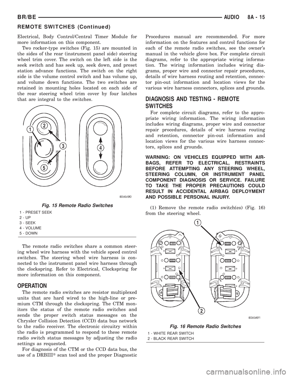
Two rocker-type switches (Fig. 15) are mounted in
the sides of the rear (instrument panel side) steering
wheel trim cover. The switch on the left side is the
seek switch and has seek up, seek down, and preset
station advance functions. The switch on the right
side is the volume control switch and has volume up,
and volume down functions. The two switches are
retained in mounting holes located on each side of
the rear steering wheel trim cover by four latches
that are integral to the switches.
The remote radio switches share a common steer-
ing wheel wire harness with the vehicle speed control
switches. The steering wheel wire harness is con-
nected to the instrument panel wire harness through
the clockspring. Refer to Electrical, Clockspring for
more information on this component.
OPERATION
The remote radio switches are resistor multiplexed
units that are hard wired to the high-line or pre-
mium CTM through the clockspring. The CTM mon-
itors the status of the remote radio switches and
sends the proper switch status messages on the
Chrysler Collision Detection (CCD) data bus network
to the radio receiver. The electronic circuitry within
the radio is programmed to respond to these remote
radio switch status messages by adjusting the radio
settings as requested.
For diagnosis of the CTM or the CCD data bus, the
use of a DRBIIItscan tool and the proper DiagnosticProcedures manual are recommended. For more
information on the features and control functions for
each of the remote radio switches, see the owner's
manual in the vehicle glove box. For complete circuit
diagrams, refer to the appropriate wiring informa-
tion. The wiring information includes wiring dia-
grams, proper wire and connector repair procedures,
details of wire harness routing and retention, connec-
tor pin-out information and location views for the
various wire harness connectors, splices and grounds.
DIAGNOSIS AND TESTING - REMOTE
SWITCHES
For complete circuit diagrams, refer to the appro-
priate wiring information. The wiring information
includes wiring diagrams, proper wire and connector
repair procedures, details of wire harness routing
and retention, connector pin-out information and
location views for the various wire harness connec-
tors, splices and grounds.
WARNING: ON VEHICLES EQUIPPED WITH AIR-
BAGS, REFER TO ELECTRICAL, RESTRAINTS
BEFORE ATTEMPTING ANY STEERING WHEEL,
STEERING COLUMN, OR INSTRUMENT PANEL
COMPONENT DIAGNOSIS OR SERVICE. FAILURE
TO TAKE THE PROPER PRECAUTIONS COULD
RESULT IN ACCIDENTAL AIRBAG DEPLOYMENT
AND POSSIBLE PERSONAL INJURY.
(1) Remove the remote radio switch(es) (Fig. 16)
from the steering wheel.
Fig. 15 Remote Radio Switches
1 - PRESET SEEK
2-UP
3 - SEEK
4 - VOLUME
5 - DOWN
Fig. 16 Remote Radio Switches
1 - WHITE REAR SWITCH
2 - BLACK REAR SWITCH
BR/BEAUDIO 8A - 15
REMOTE SWITCHES (Continued)
Page 470 of 2255
INSTALLATION
If engine has been cranked while distributor is
removed, establish the relationship between distribu-
tor shaft and number one piston position as follows:
Rotate crankshaft in a clockwise direction, as
viewed from front, until number one cylinder piston
is at top of compression stroke (compression should
be felt on finger with number one spark plug
removed). Then continue to slowly rotate engine
clockwise until indicating mark (Fig. 18) is aligned to
0 degree (TDC) mark on timing chain cover.
(1) Clean top of cylinder block for a good seal
between distributor base and block.
(2) Lightly oil the rubber o-ring seal on the distrib-
utor housing.
(3) Install rotor to distributor shaft.
(4) Position distributor into engine to its original
position. Engage tongue of distributor shaft with slot
in distributor oil pump drive gear. Position rotor to
the number one spark plug cable position.
(5) Install distributor holddown clamp and clamp
bolt. Do not tighten bolt at this time.
(6) Rotate the distributor housing until rotor is
aligned to CYL. NO. 1 alignment mark on the cam-
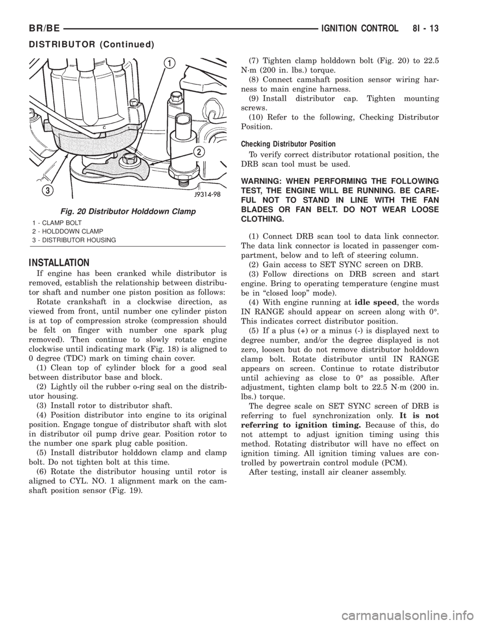
shaft position sensor (Fig. 19).(7) Tighten clamp holddown bolt (Fig. 20) to 22.5
N´m (200 in. lbs.) torque.
(8) Connect camshaft position sensor wiring har-
ness to main engine harness.
(9) Install distributor cap. Tighten mounting
screws.
(10) Refer to the following, Checking Distributor
Position.
Checking Distributor Position
To verify correct distributor rotational position, the
DRB scan tool must be used.
WARNING: WHEN PERFORMING THE FOLLOWING
TEST, THE ENGINE WILL BE RUNNING. BE CARE-
FUL NOT TO STAND IN LINE WITH THE FAN
BLADES OR FAN BELT. DO NOT WEAR LOOSE
CLOTHING.
(1) Connect DRB scan tool to data link connector.
The data link connector is located in passenger com-
partment, below and to left of steering column.
(2) Gain access to SET SYNC screen on DRB.
(3) Follow directions on DRB screen and start
engine. Bring to operating temperature (engine must
be in ªclosed loopº mode).
(4) With engine running atidle speed, the words
IN RANGE should appear on screen along with 0É.
This indicates correct distributor position.
(5) If a plus (+) or a minus (-) is displayed next to
degree number, and/or the degree displayed is not
zero, loosen but do not remove distributor holddown
clamp bolt. Rotate distributor until IN RANGE
appears on screen. Continue to rotate distributor
until achieving as close to 0É as possible. After
adjustment, tighten clamp bolt to 22.5 N´m (200 in.
lbs.) torque.
The degree scale on SET SYNC screen of DRB is
referring to fuel synchronization only.It is not
referring to ignition timing.Because of this, do
not attempt to adjust ignition timing using this
method. Rotating distributor will have no effect on
ignition timing. All ignition timing values are con-
trolled by powertrain control module (PCM).
After testing, install air cleaner assembly.
Fig. 20 Distributor Holddown Clamp
1 - CLAMP BOLT
2 - HOLDDOWN CLAMP
3 - DISTRIBUTOR HOUSING
BR/BEIGNITION CONTROL 8I - 13
DISTRIBUTOR (Continued)