bolt pattern DODGE RAM 2002 Service Owner's Manual
[x] Cancel search | Manufacturer: DODGE, Model Year: 2002, Model line: RAM, Model: DODGE RAM 2002Pages: 2255, PDF Size: 62.07 MB
Page 167 of 2255
REMOVAL
(1) Raise and support the vehicle.
(2) Position a suitable lifting device under the
axle.
(3) Secure axle to device.
(4) Remove the wheels and tires.
(5) Remove the RWAL sensor from the differential
housing, if necessary.
(6) Disconnect the brake hose at the axle junction
block.
(7) Disconnect the parking brake cables and cable
brackets.
(8)
Disconnect the vent hose from the axle shaft tube.
(9) Mark the propeller shaft and companion flange
for installation alignment reference.
(10) Remove propeller shaft.
(11) Disconnect shock absorbers from axle.
(12)
Remove the spring clamps and spring brackets.
(13) Separate the axle from the vehicle.
INSTALLATION
(1) Raise the axle with lifting device and align to
the leaf spring centering bolts.
(2) Install the spring clamps and spring brackets.
(3) Install the shock absorbers.
(4) Install the RWAL sensor to the differential
housing, if necessary
(5) Install the parking brake cables and cable
brackets.
(6)
Install the brake hose to the axle junction block.
(7) Install axle vent hose.
(8) Install the propeller shaft with reference marks
aligned.
(9) Install the wheels and tires.
(10) Add gear lubricant, if necessary. Refer to
Specifications for lubricant requirements.
(11) Remove lifting device from axle and lower the
vehicle.
ADJUSTMENTS
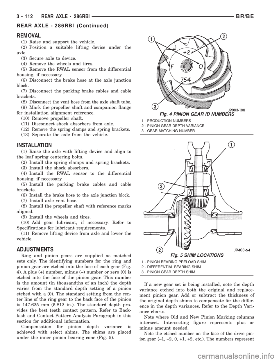
Ring and pinion gears are supplied as matched
sets only. The identifying numbers for the ring and
pinion gear are etched into the face of each gear (Fig.
4). A plus (+) number, minus (±) number or zero (0) is
etched into the face of the pinion gear. This number
is the amount (in thousandths of an inch) the depth
varies from the standard depth setting of a pinion
etched with a (0). The standard setting from the cen-
ter line of the ring gear to the back face of the pinion
is 147.625 mm (5.812 in.). The standard depth pro-
vides the best teeth contact pattern. Refer to Back-
lash and Contact Pattern Analysis Paragraph in this
section for additional information.
Compensation for pinion depth variance is
achieved with select shims. The shims are placed
under the inner pinion bearing cone (Fig. 5).If a new gear set is being installed, note the depth
variance etched into both the original and replace-
ment pinion gear. Add or subtract the thickness of
the original depth shims to compensate for the differ-
ence in the depth variances. Refer to the Depth Vari-
ance charts.
Note where Old and New Pinion Marking columns
intersect. Intersecting figure represents plus or
minus amount needed.
Note the etched number on the face of the drive pin-
ion gear (±1, ±2, 0, +1, +2, etc.). The numbers represent
Fig. 4 PINION GEAR ID NUMBERS
1 - PRODUCTION NUMBERS
2 - PINION GEAR DEPTH VARIANCE
3 - GEAR MATCHING NUMBER
Fig. 5 SHIM LOCATIONS
1 - PINION BEARING PRELOAD SHIM
2 - DIFFERENTIAL BEARING SHIM
3 - PINION GEAR DEPTH SHIM
3 - 112 REAR AXLE - 286RBIBR/BE
REAR AXLE - 286RBI (Continued)
Page 168 of 2255
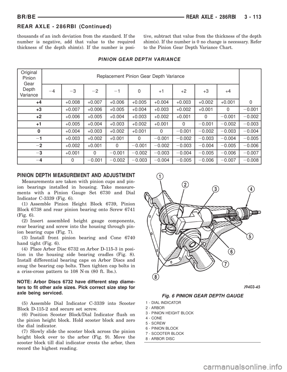
thousands of an inch deviation from the standard. If the
number is negative, add that value to the required
thickness of the depth shim(s). If the number is posi-tive, subtract that value from the thickness of the depth
shim(s). If the number is 0 no change is necessary. Refer
to the Pinion Gear Depth Variance Chart.
PINION GEAR DEPTH VARIANCE
Original
Pinion
Gear
Depth
VarianceReplacement Pinion Gear Depth Variance
24232221 0 +1 +2 +3 +4
+4+0.008 +0.007 +0.006 +0.005 +0.004 +0.003 +0.002 +0.001 0
+3+0.007 +0.006 +0.005 +0.004 +0.003 +0.002 +0.001 020.001
+2+0.006 +0.005 +0.004 +0.003 +0.002 +0.001 020.00120.002
+1+0.005 +0.004 +0.003 +0.002 +0.001 020.00120.00220.003
0+0.004 +0.003 +0.002 +0.001 020.00120.00220.00320.004
21+0.003 +0.002 +0.001 020.00120.00220.00320.00420.005
22+0.002 +0.001 020.00120.00220.00320.00420.00520.006
23+0.001 020.00120.00220.00320.00420.00520.00620.007
24020.00120.00220.00320.00420.00520.00620.00720.008
PINION DEPTH MEASUREMENT AND ADJUSTMENT
Measurements are taken with pinion cups and pin-
ion bearings installed in housing. Take measure-
ments with a Pinion Gauge Set 6730 and Dial
Indicator C-3339 (Fig. 6).
(1) Assemble Pinion Height Block 6739, Pinion
Block 6738 and rear pinion bearing onto Screw 6741
(Fig. 6).
(2) Insert assembled height gauge components,
rear bearing and screw into the housing through pin-
ion bearing cups (Fig. 7).
(3) Install front pinion bearing and Cone 6740
hand tight (Fig. 6).
(4) Place Arbor Disc 6732 on Arbor D-115-3 in posi-
tion in the housing side bearing cradles (Fig. 8).
Install differential bearing caps on Arbor Discs and
snug the bearing cap bolts. Then tighten cap bolts in
a criss-cross pattern to 108 N´m (80 ft. lbs.).
NOTE: Arbor Discs 6732 have different step diame-
ters to fit other axle sizes. Pick correct size step for
axle being serviced.
(5) Assemble Dial Indicator C-3339 into Scooter
Block D-115-2 and secure set screw.
(6) Position Scooter Block/Dial Indicator flush on
the pinion height block. Hold scooter block and zero
the dial indicator.
(7) Slowly slide the scooter block across the pinion
height block over to the arbor (Fig. 9). Move the
scooter block till dial indicator crests the arbor, then
record the highest reading.
Fig. 6 PINION GEAR DEPTH GAUGE
1 - DIAL INDICATOR
2 - ARBOR
3 - PINION HEIGHT BLOCK
4 - CONE
5 - SCREW
6 - PINION BLOCK
7 - SCOOTER BLOCK
8 - ARBOR DISC
BR/BEREAR AXLE - 286RBI 3 - 113
REAR AXLE - 286RBI (Continued)
Page 169 of 2255
(8) Select a shim equal to the dial indicator read-
ing plus the drive pinion gear depth variance number
etched in the face of the pinion gear (Fig. 4) using
the opposite sign on the variance number. For exam-
ple, if the depth variance is ±2, add +0.002 in. to the
dial indicator reading.
(9) Remove the pinion depth gauge components
from the axle housing
DIFFERENTIAL BEARING PRELOAD AND GEAR
BACKLASH
Differential side bearing preload and gear backlash
is achieved by selective shims positioned behind thedifferential side bearing cones. The proper shim
thickness can be determined using slip-fit dummy
bearings D-346 in place of the differential side bear-
ings and a dial indicator C-3339. Before proceeding
with the differential bearing preload and gear back-
lash measurements, measure the pinion gear depth
and prepare the pinion gear for installation. Estab-
lishing proper pinion gear depth is essential to estab-
lishing gear backlash and tooth contact patterns.
After the overall shim thickness to take up differen-
tial side play is measured, the pinion gear is
installed, and the gear backlash shim thickness is
measured. The overall shim thickness is the total of
the dial indicator reading and the preload specifica-
tion added together. The gear backlash measurement
determines the thickness of the shim used on the
ring gear side of the differential case. Subtract the
gear backlash shim thickness from the total overall
shim thickness and select that amount for the pinion
gear side of the differential (Fig. 10). Differential
shim measurements are performed with axle
spreader W-129-B removed.
SHIM SELECTION
NOTE: It is difficult to salvage the differential side
bearings during the removal procedure. Install
replacement bearings if necessary.
(1) Remove differential side bearings from differ-
ential case.
(2) Remove factory installed shims from differen-
tial case.
(3) Install ring gear on differential case and
tighten bolts to specification, if necessary.
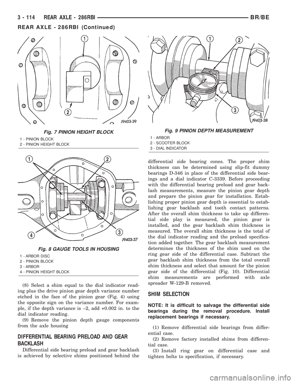
Fig. 7 PINION HEIGHT BLOCK
1 - PINION BLOCK
2 - PINION HEIGHT BLOCK
Fig. 8 GAUGE TOOLS IN HOUSING
1 - ARBOR DISC
2 - PINION BLOCK
3 - ARBOR
4 - PINION HEIGHT BLOCK
Fig. 9 PINION DEPTH MEASUREMENT
1 - ARBOR
2 - SCOOTER BLOCK
3 - DIAL INDICATOR
3 - 114 REAR AXLE - 286RBIBR/BE
REAR AXLE - 286RBI (Continued)
Page 173 of 2255
(33) Push and hold ring gear upward while not
allowing the pinion gear to rotate.
(34) Zero dial indicator face to pointer.
(35) Push and hold ring gear downward while not
allowing the pinion gear to rotate. Dial indicator
reading should be between 0.12 mm (0.005 in.) and
0.20 mm (0.008 in.). If backlash is not within specifi-
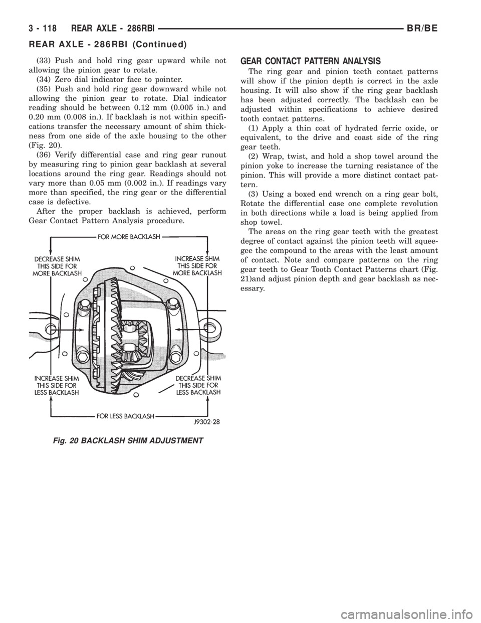
cations transfer the necessary amount of shim thick-
ness from one side of the axle housing to the other
(Fig. 20).
(36) Verify differential case and ring gear runout
by measuring ring to pinion gear backlash at several
locations around the ring gear. Readings should not
vary more than 0.05 mm (0.002 in.). If readings vary
more than specified, the ring gear or the differential
case is defective.
After the proper backlash is achieved, perform
Gear Contact Pattern Analysis procedure.GEAR CONTACT PATTERN ANALYSIS
The ring gear and pinion teeth contact patterns
will show if the pinion depth is correct in the axle
housing. It will also show if the ring gear backlash
has been adjusted correctly. The backlash can be
adjusted within specifications to achieve desired
tooth contact patterns.
(1) Apply a thin coat of hydrated ferric oxide, or
equivalent, to the drive and coast side of the ring
gear teeth.
(2) Wrap, twist, and hold a shop towel around the
pinion yoke to increase the turning resistance of the
pinion. This will provide a more distinct contact pat-
tern.
(3) Using a boxed end wrench on a ring gear bolt,
Rotate the differential case one complete revolution
in both directions while a load is being applied from
shop towel.
The areas on the ring gear teeth with the greatest
degree of contact against the pinion teeth will squee-
gee the compound to the areas with the least amount
of contact. Note and compare patterns on the ring
gear teeth to Gear Tooth Contact Patterns chart (Fig.
21)and adjust pinion depth and gear backlash as nec-
essary.
Fig. 20 BACKLASH SHIM ADJUSTMENT
3 - 118 REAR AXLE - 286RBIBR/BE
REAR AXLE - 286RBI (Continued)
Page 182 of 2255
(1) Position Spreader W-129-B with the tool dowel
pins seated in the locating holes. Install the hold
down clamps and tighten the tool turnbuckle finger-
tight.
(2) Install a Pilot Stud C-3288-B at the left side of
the differential housing and attach dial indicator to
the pilot stud. Load the indicator plunger against the
opposite side of the housing and zero the dial indica-
tor.
(3) Spread the housing enough to install the case
in the housing. Measure the distance with the dial
indicator.
CAUTION: Never spread the housing over 0.50 mm
(0.020 in). If housing is over-spread, it could be dis-
torted or damaged.
(4) Remove the dial indicator.
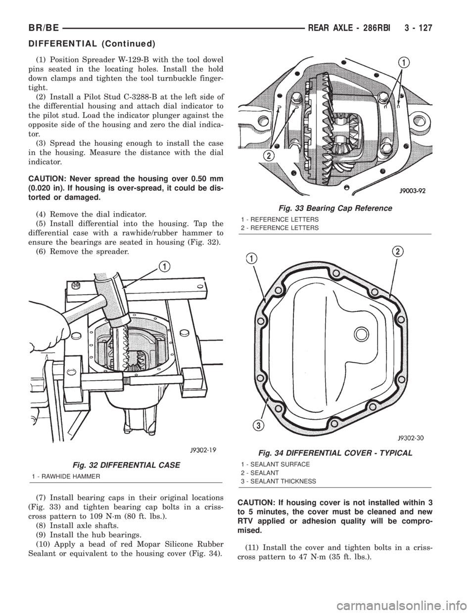
(5) Install differential into the housing. Tap the
differential case with a rawhide/rubber hammer to
ensure the bearings are seated in housing (Fig. 32).
(6) Remove the spreader.
(7) Install bearing caps in their original locations
(Fig. 33) and tighten bearing cap bolts in a criss-
cross pattern to 109 N´m (80 ft. lbs.).
(8) Install axle shafts.
(9) Install the hub bearings.
(10) Apply a bead of red Mopar Silicone Rubber
Sealant or equivalent to the housing cover (Fig. 34).CAUTION: If housing cover is not installed within 3
to 5 minutes, the cover must be cleaned and new
RTV applied or adhesion quality will be compro-
mised.
(11) Install the cover and tighten bolts in a criss-
cross pattern to 47 N´m (35 ft. lbs.).
Fig. 32 DIFFERENTIAL CASE
1 - RAWHIDE HAMMER
Fig. 33 Bearing Cap Reference
1 - REFERENCE LETTERS
2 - REFERENCE LETTERS
Fig. 34 DIFFERENTIAL COVER - TYPICAL
1 - SEALANT SURFACE
2 - SEALANT
3 - SEALANT THICKNESS
BR/BEREAR AXLE - 286RBI 3 - 127
DIFFERENTIAL (Continued)
Page 189 of 2255
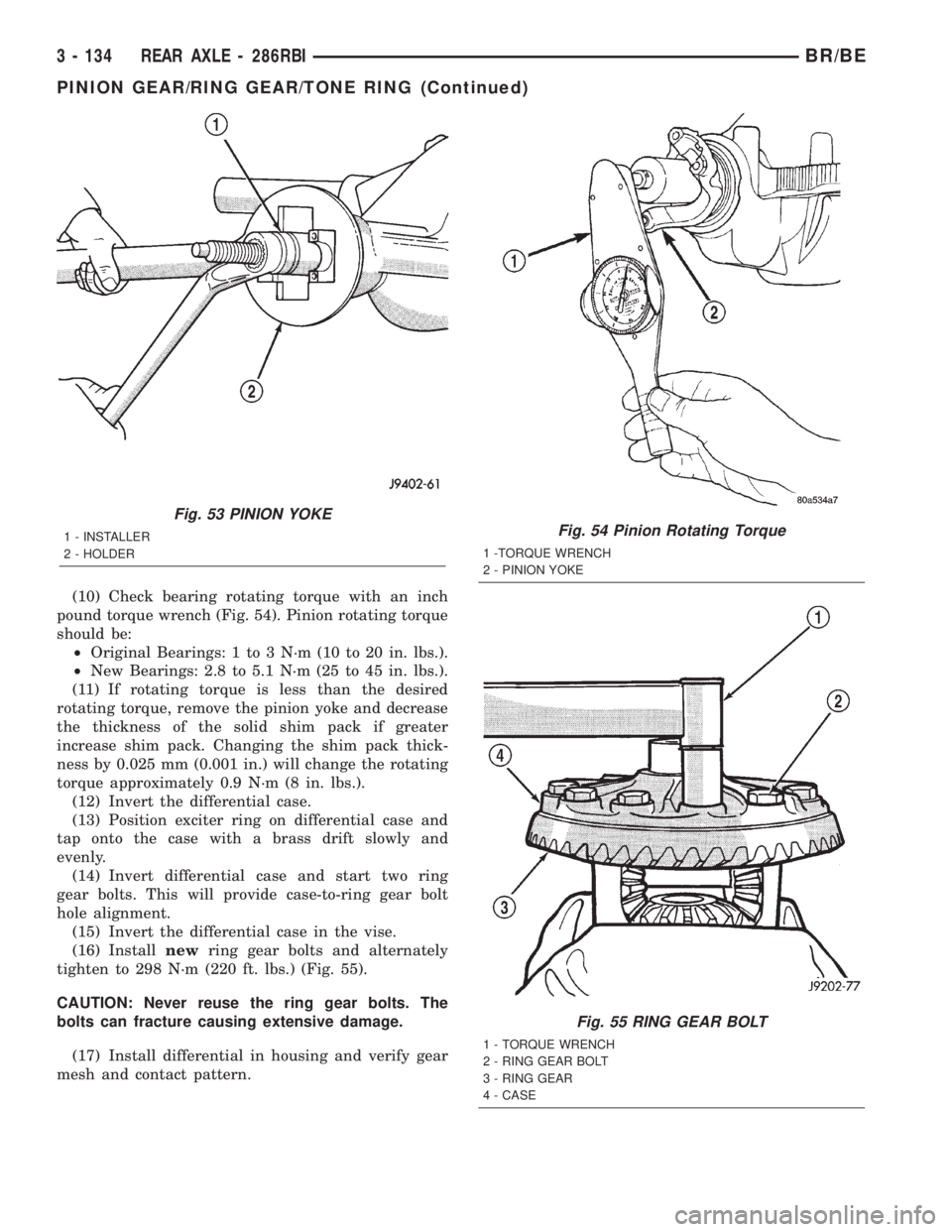
(10) Check bearing rotating torque with an inch
pound torque wrench (Fig. 54). Pinion rotating torque
should be:
²Original Bearings: 1 to 3 N´m (10 to 20 in. lbs.).
²New Bearings: 2.8 to 5.1 N´m (25 to 45 in. lbs.).
(11) If rotating torque is less than the desired
rotating torque, remove the pinion yoke and decrease
the thickness of the solid shim pack if greater
increase shim pack. Changing the shim pack thick-
ness by 0.025 mm (0.001 in.) will change the rotating
torque approximately 0.9 N´m (8 in. lbs.).
(12) Invert the differential case.
(13) Position exciter ring on differential case and
tap onto the case with a brass drift slowly and
evenly.
(14) Invert differential case and start two ring
gear bolts. This will provide case-to-ring gear bolt
hole alignment.
(15) Invert the differential case in the vise.
(16) Installnewring gear bolts and alternately
tighten to 298 N´m (220 ft. lbs.) (Fig. 55).
CAUTION: Never reuse the ring gear bolts. The
bolts can fracture causing extensive damage.
(17) Install differential in housing and verify gear
mesh and contact pattern.
Fig. 53 PINION YOKE
1 - INSTALLER
2 - HOLDERFig. 54 Pinion Rotating Torque
1 -TORQUE WRENCH
2 - PINION YOKE
Fig. 55 RING GEAR BOLT
1 - TORQUE WRENCH
2 - RING GEAR BOLT
3 - RING GEAR
4 - CASE
3 - 134 REAR AXLE - 286RBIBR/BE
PINION GEAR/RING GEAR/TONE RING (Continued)
Page 239 of 2255
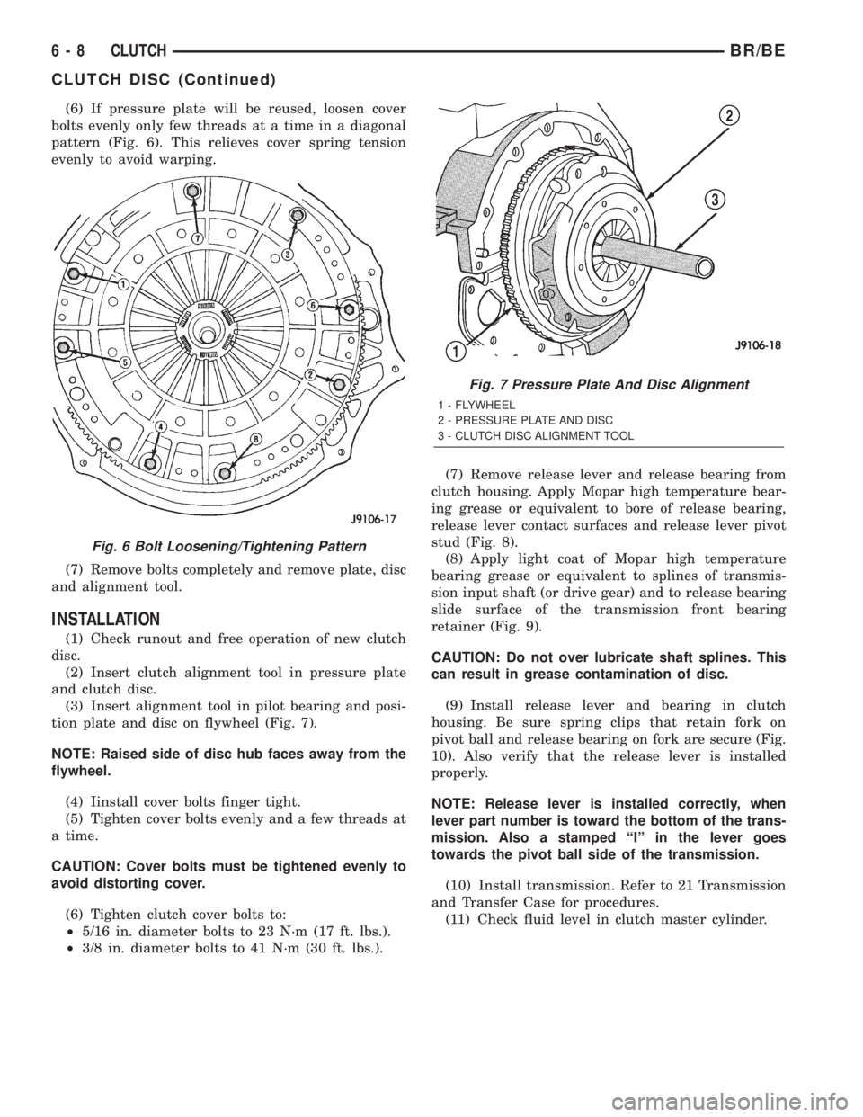
(6) If pressure plate will be reused, loosen cover
bolts evenly only few threads at a time in a diagonal
pattern (Fig. 6). This relieves cover spring tension
evenly to avoid warping.
(7) Remove bolts completely and remove plate, disc
and alignment tool.
INSTALLATION
(1) Check runout and free operation of new clutch
disc.
(2) Insert clutch alignment tool in pressure plate
and clutch disc.
(3) Insert alignment tool in pilot bearing and posi-
tion plate and disc on flywheel (Fig. 7).
NOTE: Raised side of disc hub faces away from the
flywheel.
(4) Iinstall cover bolts finger tight.
(5) Tighten cover bolts evenly and a few threads at
a time.
CAUTION: Cover bolts must be tightened evenly to
avoid distorting cover.
(6) Tighten clutch cover bolts to:
²5/16 in. diameter bolts to 23 N´m (17 ft. lbs.).
²3/8 in. diameter bolts to 41 N´m (30 ft. lbs.).(7) Remove release lever and release bearing from
clutch housing. Apply Mopar high temperature bear-
ing grease or equivalent to bore of release bearing,
release lever contact surfaces and release lever pivot
stud (Fig. 8).
(8) Apply light coat of Mopar high temperature
bearing grease or equivalent to splines of transmis-
sion input shaft (or drive gear) and to release bearing
slide surface of the transmission front bearing
retainer (Fig. 9).
CAUTION: Do not over lubricate shaft splines. This
can result in grease contamination of disc.
(9) Install release lever and bearing in clutch
housing. Be sure spring clips that retain fork on
pivot ball and release bearing on fork are secure (Fig.
10). Also verify that the release lever is installed
properly.
NOTE: Release lever is installed correctly, when
lever part number is toward the bottom of the trans-
mission. Also a stamped ªIº in the lever goes
towards the pivot ball side of the transmission.
(10) Install transmission. Refer to 21 Transmission
and Transfer Case for procedures.
(11) Check fluid level in clutch master cylinder.
Fig. 6 Bolt Loosening/Tightening Pattern
Fig. 7 Pressure Plate And Disc Alignment
1 - FLYWHEEL
2 - PRESSURE PLATE AND DISC
3 - CLUTCH DISC ALIGNMENT TOOL
6 - 8 CLUTCHBR/BE
CLUTCH DISC (Continued)
Page 279 of 2255
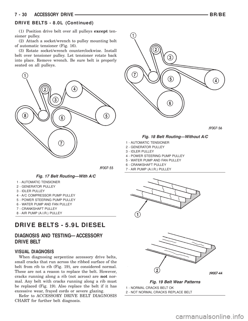
(1) Position drive belt over all pulleysexceptten-
sioner pulley.
(2) Attach a socket/wrench to pulley mounting bolt
of automatic tensioner (Fig. 16).
(3) Rotate socket/wrench counterclockwise. Install
belt over tensioner pulley. Let tensioner rotate back
into place. Remove wrench. Be sure belt is properly
seated on all pulleys.
DRIVE BELTS - 5.9L DIESEL
DIAGNOSIS AND TESTINGÐACCESSORY
DRIVE BELT
VISUAL DIAGNOSIS
When diagnosing serpentine accessory drive belts,
small cracks that run across the ribbed surface of the
belt from rib to rib (Fig. 19), are considered normal.
These are not a reason to replace the belt. However,
cracks running along a rib (not across) arenotnor-
mal. Any belt with cracks running along a rib must
be replaced (Fig. 19). Also replace the belt if it has
excessive wear, frayed cords or severe glazing.
Refer to ACCESSORY DRIVE BELT DIAGNOSIS
CHART for further belt diagnosis.
Fig. 17 Belt RoutingÐWith A/C
1 - AUTOMATIC TENSIONER
2 - GENERATOR PULLEY
3 - IDLER PULLEY
4 - A/C COMPRESSOR PUMP PULLEY
5 - POWER STEERING PUMP PULLEY
6 - WATER PUMP AND FAN PULLEY
7 - CRANKSHAFT PULLEY
8 - AIR PUMP (A.I.R.) PULLEY
Fig. 18 Belt RoutingÐWithout A/C
1 - AUTOMATIC TENSIONER
2 - GENERATOR PULLEY
3 - IDLER PULLEY
4 - POWER STEERING PUMP PULLEY
5 - WATER PUMP AND FAN PULLEY
6 - CRANKSHAFT PULLEY
7 - AIR PUMP (A.I.R.) PULLEY
Fig. 19 Belt Wear Patterns
1 - NORMAL CRACKS BELT OK
2 - NOT NORMAL CRACKS REPLACE BELT
7 - 30 ACCESSORY DRIVEBR/BE
DRIVE BELTS - 8.0L (Continued)
Page 1087 of 2255
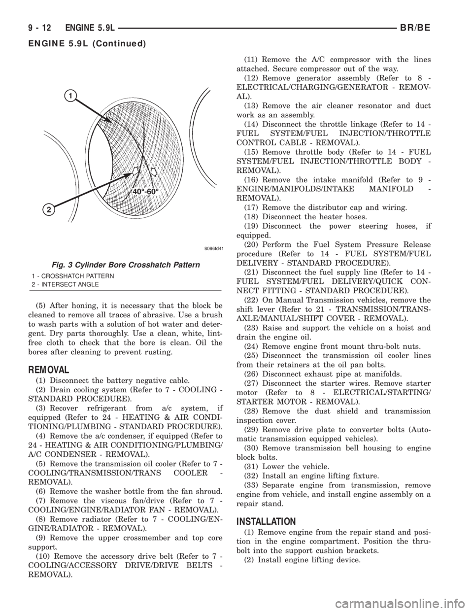
(5) After honing, it is necessary that the block be
cleaned to remove all traces of abrasive. Use a brush
to wash parts with a solution of hot water and deter-
gent. Dry parts thoroughly. Use a clean, white, lint-
free cloth to check that the bore is clean. Oil the
bores after cleaning to prevent rusting.
REMOVAL
(1) Disconnect the battery negative cable.
(2) Drain cooling system (Refer to 7 - COOLING -
STANDARD PROCEDURE).
(3) Recover refrigerant from a/c system, if
equipped (Refer to 24 - HEATING & AIR CONDI-
TIONING/PLUMBING - STANDARD PROCEDURE).
(4) Remove the a/c condenser, if equipped (Refer to
24 - HEATING & AIR CONDITIONING/PLUMBING/
A/C CONDENSER - REMOVAL).
(5) Remove the transmission oil cooler (Refer to 7 -
COOLING/TRANSMISSION/TRANS COOLER -
REMOVAL).
(6) Remove the washer bottle from the fan shroud.
(7) Remove the viscous fan/drive (Refer to 7 -
COOLING/ENGINE/RADIATOR FAN - REMOVAL).
(8) Remove radiator (Refer to 7 - COOLING/EN-
GINE/RADIATOR - REMOVAL).
(9) Remove the upper crossmember and top core
support.
(10) Remove the accessory drive belt (Refer to 7 -
COOLING/ACCESSORY DRIVE/DRIVE BELTS -
REMOVAL).(11) Remove the A/C compressor with the lines
attached. Secure compressor out of the way.
(12) Remove generator assembly (Refer to 8 -
ELECTRICAL/CHARGING/GENERATOR - REMOV-
AL).
(13) Remove the air cleaner resonator and duct
work as an assembly.
(14) Disconnect the throttle linkage (Refer to 14 -
FUEL SYSTEM/FUEL INJECTION/THROTTLE
CONTROL CABLE - REMOVAL).
(15) Remove throttle body (Refer to 14 - FUEL
SYSTEM/FUEL INJECTION/THROTTLE BODY -
REMOVAL).
(16) Remove the intake manifold (Refer to 9 -
ENGINE/MANIFOLDS/INTAKE MANIFOLD -
REMOVAL).
(17) Remove the distributor cap and wiring.
(18) Disconnect the heater hoses.
(19) Disconnect the power steering hoses, if
equipped.
(20) Perform the Fuel System Pressure Release
procedure (Refer to 14 - FUEL SYSTEM/FUEL
DELIVERY - STANDARD PROCEDURE).
(21) Disconnect the fuel supply line (Refer to 14 -
FUEL SYSTEM/FUEL DELIVERY/QUICK CON-
NECT FITTING - STANDARD PROCEDURE).
(22) On Manual Transmission vehicles, remove the
shift lever (Refer to 21 - TRANSMISSION/TRANS-
AXLE/MANUAL/SHIFT COVER - REMOVAL).
(23) Raise and support the vehicle on a hoist and
drain the engine oil.
(24) Remove engine front mount thru-bolt nuts.
(25) Disconnect the transmission oil cooler lines
from their retainers at the oil pan bolts.
(26) Disconnect exhaust pipe at manifolds.
(27) Disconnect the starter wires. Remove starter
motor (Refer to 8 - ELECTRICAL/STARTING/
STARTER MOTOR - REMOVAL).
(28) Remove the dust shield and transmission
inspection cover.
(29) Remove drive plate to converter bolts (Auto-
matic transmission equipped vehicles).
(30) Remove transmission bell housing to engine
block bolts.
(31) Lower the vehicle.
(32) Install an engine lifting fixture.
(33) Separate engine from transmission, remove
engine from vehicle, and install engine assembly on a
repair stand.
INSTALLATION
(1) Remove engine from the repair stand and posi-
tion in the engine compartment. Position the thru-
bolt into the support cushion brackets.
(2) Install engine lifting device.
Fig. 3 Cylinder Bore Crosshatch Pattern
1 - CROSSHATCH PATTERN
2 - INTERSECT ANGLE
9 - 12 ENGINE 5.9LBR/BE
ENGINE 5.9L (Continued)
Page 1213 of 2255
INSPECTION
The cylinder head cover gasket and isolators
are reusable.However, should cracks be present in
the rubber/silicone construction, the defective compo-
nents should be replaced.
INSTALLATION
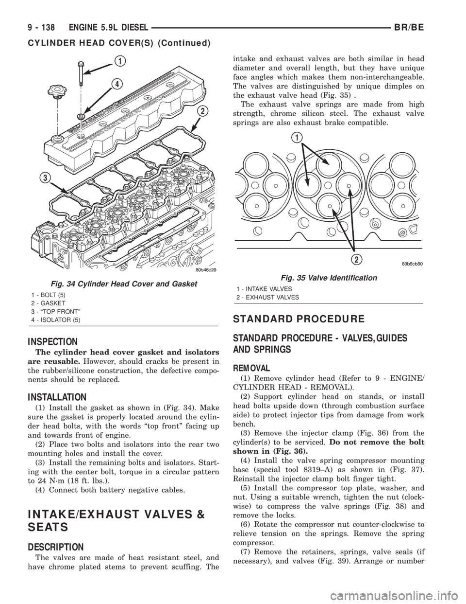
(1) Install the gasket as shown in (Fig. 34). Make
sure the gasket is properly located around the cylin-
der head bolts, with the words ªtop frontº facing up
and towards front of engine.
(2) Place two bolts and isolators into the rear two
mounting holes and install the cover.
(3) Install the remaining bolts and isolators. Start-
ing with the center bolt, torque in a circular pattern
to 24 N´m (18 ft. lbs.).
(4) Connect both battery negative cables.
INTAKE/EXHAUST VALVES &
SEATS
DESCRIPTION
The valves are made of heat resistant steel, and
have chrome plated stems to prevent scuffing. Theintake and exhaust valves are both similar in head
diameter and overall length, but they have unique
face angles which makes them non-interchangeable.
The valves are distinguished by unique dimples on
the exhaust valve head (Fig. 35) .
The exhaust valve springs are made from high
strength, chrome silicon steel. The exhaust valve
springs are also exhaust brake compatible.
STANDARD PROCEDURE
STANDARD PROCEDURE - VALVES,GUIDES
AND SPRINGS
REMOVAL
(1) Remove cylinder head (Refer to 9 - ENGINE/
CYLINDER HEAD - REMOVAL).
(2) Support cylinder head on stands, or install
head bolts upside down (through combustion surface
side) to protect injector tips from damage from work
bench.
(3) Remove the injector clamp (Fig. 36) from the
cylinder(s) to be serviced.Do not remove the bolt
shown in (Fig. 36).
(4) Install the valve spring compressor mounting
base (special tool 8319±A) as shown in (Fig. 37).
Reinstall the injector clamp bolt finger tight.
(5) Install the compressor top plate, washer, and
nut. Using a suitable wrench, tighten the nut (clock-
wise) to compress the valve springs (Fig. 38) and
remove the locks.
(6) Rotate the compressor nut counter-clockwise to
relieve tension on the springs. Remove the spring
compressor.
(7) Remove the retainers, springs, valve seals (if
necessary), and valves (Fig. 39). Arrange or number
Fig. 34 Cylinder Head Cover and Gasket
1 - BOLT (5)
2 - GASKET
3 - ªTOP FRONTº
4 - ISOLATOR (5)
Fig. 35 Valve Identification
1 - INTAKE VALVES
2 - EXHAUST VALVES
9 - 138 ENGINE 5.9L DIESELBR/BE
CYLINDER HEAD COVER(S) (Continued)