key battery DODGE RAM 2002 Service Owner's Guide
[x] Cancel search | Manufacturer: DODGE, Model Year: 2002, Model line: RAM, Model: DODGE RAM 2002Pages: 2255, PDF Size: 62.07 MB
Page 617 of 2255
switch is in its installed position, the only compo-
nents visible through the dedicated opening of the
cluster bezel are the switch face plate and nomencla-
ture, the key cylinder actuator, and a small round
lens with the text9Off9imprinted on it. The ªOnº
position of the switch is designated by text imprinted
upon the face plate of the switch, but is not illumi-
nated. The remainder of the switch is concealed
behind the switch face plate and the instrument
panel cluster bezel.
The passenger airbag on-off switch housing is con-
structed of molded plastic and has three integral
mounting tabs. These mounting tabs are used to
secure the switch to the back of the molded plastic
switch face plate with three small screws. The
molded plastic face plate also has three integral
mounting tabs that are used to secure the switch and
face plate unit to the instrument panel carrier with
three additional screws. Two short pigtail wires with
molded plastic connector insulators exit the back of
the switch housing and connect the switch to the
vehicle electrical system through two dedicated take
outs of the instrument panel wire harness. The har-
ness take outs are equipped with molded plastic con-
nector insulators that are keyed and latched to
ensure proper and secure switch electrical connec-
tions. The passenger airbag on/off switch cannot be
adjusted or repaired and, if faulty or damaged, the
switch must be replaced.
OPERATION
The passenger airbag on/off switch allows the cus-
tomer to turn the passenger airbag function On or
Off to accommodate certain uses of the right front
seating position where airbag protection may not be
desired. See the owner's manual in the vehicle glove
box for specific recommendations on when to enable
or disable the passenger airbag. The Off indicator of
the switch will be illuminated whenever the switch is
turned to the Off position. The ignition key is the
only key or object that should ever be inserted into
the switch. The on/off switch requires only a partial
key insertion to fully depress a spring-loaded locking
plunger. The spring-loaded locking plunger prevents
the user from leaving the key in the switch. The key
will be automatically ejected when force is not
applied. To actuate the passenger side airbag on/off
switch, insert the ignition key into the switch key
actuator far enough to fully depress the plunger and
rotate to the desired switch position. When the
switch key actuator is rotated to its clockwise stop
(the key actuator slot will be aligned with the Off
indicator lamp), the Off indicator is illuminated and
the passenger airbag is disabled. When the switch is
rotated to its counterclockwise stop (the key actuator
slot will be in a vertical position), the Off indicatorwill be extinguished and the passenger airbag is
enabled.
The passenger airbag on/off switch is connected in
series between the Airbag Control Module (ACM) and
the passenger airbag inflator unit. When the switch
is in the On position, the switch connects the ACM
directly to the passenger airbag inflator. When the
switch is in the Off position it interrupts the inflator
circuits, but replaces the normal resistance in these
circuits with an internal resistor. Thus, the ACM is
unable to distinguish the mode of the switch and still
sends an electrical signal as though it were deploying
the passenger airbag when it detects a sufficient
impact. However, the switch position should not be
changed while the ignition switch is in the On posi-
tion, as the ACM may detect a fault, record a Diag-
nostic Trouble Code (DTC), and illuminate the Airbag
indicator in response to a momentary open it senses
in the passenger airbag inflator circuits as the on/off
switch changes states.
REMOVAL
WARNING: DISABLE THE AIRBAG SYSTEM
BEFORE ATTEMPTING ANY STEERING WHEEL,
STEERING COLUMN, OR INSTRUMENT PANEL
COMPONENT DIAGNOSIS OR SERVICE. DISCON-
NECT AND ISOLATE THE BATTERY NEGATIVE
(GROUND) CABLE, THEN WAIT TWO MINUTES FOR
THE AIRBAG SYSTEM CAPACITOR TO DISCHARGE
BEFORE PERFORMING FURTHER DIAGNOSIS OR
SERVICE. THIS IS THE ONLY SURE WAY TO DIS-
ABLE THE AIRBAG SYSTEM. FAILURE TO TAKE
THE PROPER PRECAUTIONS COULD RESULT IN
ACCIDENTAL AIRBAG DEPLOYMENT AND POSSI-
BLE PERSONAL INJURY.
(1) Disconnect and isolate the battery negative
cable. If either of the airbags has not been deployed,
wait two minutes for the system capacitor to dis-
charge before further service.
(2) Remove the cluster bezel from the instrument
panel. (Refer to 23 - BODY/INSTRUMENT PANEL/
CLUSTER BEZEL - REMOVAL).
(3) Remove the glove box from the instrument
panel. (Refer to 23 - BODY/INSTRUMENT PANEL/
GLOVE BOX - REMOVAL).
(4) Reach through the glove box opening to access
and disconnect the two passenger airbag on/off
switch pigtail wire harness connectors from the
instrument panel wire harness connectors. These
connectors are retained on a bracket located on the
inboard glove box opening reinforcement (Fig. 20).
(5) Remove the three screws that secure the pas-
senger airbag on/off switch face plate to the instru-
ment panel (Fig. 21).
8O - 24 RESTRAINTSBR/BE
PASSENGER AIRBAG ON/OFF SWITCH (Continued)
Page 640 of 2255
VEHICLE THEFT SECURITY
TABLE OF CONTENTS
page page
VEHICLE THEFT SECURITY
DESCRIPTION..........................1
OPERATION............................2
DIAGNOSIS AND TESTING - VEHICLE THEFT
SECURITY SYSTEM....................3VTSS INDICATOR
DESCRIPTION..........................3
OPERATION............................3
DIAGNOSIS AND TESTING - VTSS
INDICATOR...........................4
VEHICLE THEFT SECURITY
DESCRIPTION
The Vehicle Theft Security System (VTSS) is an
available factory-installed option on this model when
it is also equipped with the high-line or premium
Central Timer Module (CTM). The VTSS is designed
to provide perimeter protection against unauthorized
use or tampering by monitoring the vehicle doors and
the ignition system. If unauthorized vehicle use or
tampering is detected, the system responds by puls-
ing the horn, flashing the headlamps, and preventing
the engine from operating.
The VTSS includes the following major compo-
nents, which are described in further detail else-
where in this service manual:
²Central Timer Module- The high-line or pre-
mium Central Timer Module (CTM) is located under
the driver side end of the instrument panel, inboard
of the instrument panel steering column opening.
The high-line or premium CTM contains a micropro-
cessor and software that allow it to provide many
electronic functions and features not available with
base version of the CTM, including the VTSS. The
CTM provides all of the proper VTSS features and
outputs based upon the monitored inputs. The CTM
circuitry monitors hard wired switch inputs, as well
as message inputs received from other vehicle elec-
tronic modules over the Chrysler Collision Detection
(CCD) data bus network. (Refer to 8 - ELECTRICAL/
ELECTRONIC CONTROL MODULES/BODY CON-
TROL/CENTRAL TIMER MODULE -
DESCRIPTION).
²Door Ajar Switch- A door ajar switch is
located on the hinge pillar of each front door in the
vehicle. These switches provide an input to the VTSS
indicating whether the door is opened or closed.
(Refer to 8 - ELECTRICAL/LAMPS/LIGHTING -
INTERIOR/DOOR AJAR SWITCH - DESCRIPTION).
²Door Cylinder Lock Switch- A door cylinder
lock switch is located on the back of each front door
lock cylinder. This switch provides an input to theVTSS indicating whether the system should remain
armed or be disarmed. (Refer to 8 - ELECTRICAL/
POWER LOCKS/DOOR CYLINDER LOCK SWITCH
- DESCRIPTION).
²Horn Relay- The horn relay is located in the
Power Distribution Center (PDC) in the engine com-
partment near the battery. The horn relay is nor-
mally activated by the horn switch to control the
sounding of the vehicle horn or horns. However, it
can also be activated by an output of the Central
Timer Module (CTM) to provide an audible indication
that unauthorized vehicle use or tampering has been
detected. (Refer to 8 - ELECTRICAL/HORN/HORN
RELAY - DESCRIPTION).
²Headlamp Relay- The headlamp relay (also
known as the security relay) is located in the Power
Distribution Center (PDC) in the engine compart-
ment near the battery. The headlamp relay is nor-
mally activated by the Central Timer Module (CTM)
based upon inputs from the Remote Keyless Entry
(RKE) panic mode feature. However, it can also be
activated by an output of the CTM to flash the head-
lamp low beams to provide a highly visible indication
that unauthorized vehicle use or tampering has been
detected. (Refer to 8 - ELECTRICAL/LAMPS/LIGHT-
ING - EXTERIOR/HEADLAMP RELAY - DESCRIP-
TION).
²VTSS Indicator- A red Light Emitting Diode
(LED) located on the lower surface of the overhead
console near the windshield is illuminated by an out-
put of the Central Timer Module (CTM) to indicate
the status of the VTSS. This LED is integral to the
electronic circuit board for the Compass Mini-Trip
Computer (CMTC). (Refer to 8 - ELECTRICAL/
OVERHEAD CONSOLE/COMPASS/MINI-TRIP
COMPUTER - DESCRIPTION).
The engine no-run feature of the VTSS relies upon
communication between the high-line or premium
CTM and the Powertrain Control Module (PCM) over
the Chrysler Collision Detection (CCD) data bus net-
work.
BR/BEVEHICLE THEFT SECURITY 8Q - 1
Page 653 of 2255
REMOVAL
(1) Disconnect and isolate the battery negative
cable.
(2) Disconnect the headlamp and dash wire har-
ness connector for the washer pump/motor from the
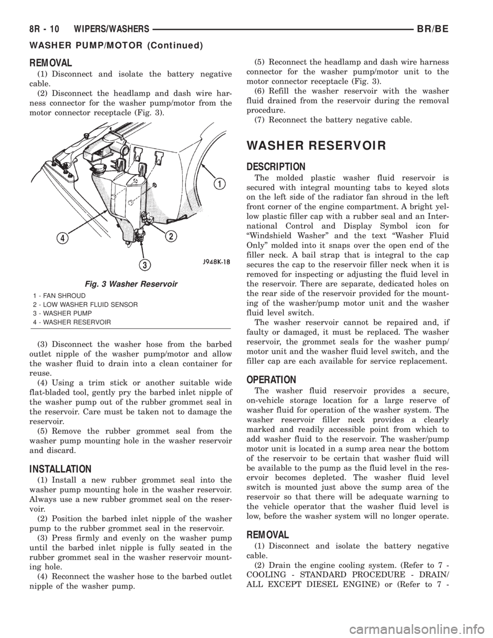
motor connector receptacle (Fig. 3).
(3) Disconnect the washer hose from the barbed
outlet nipple of the washer pump/motor and allow
the washer fluid to drain into a clean container for
reuse.
(4) Using a trim stick or another suitable wide
flat-bladed tool, gently pry the barbed inlet nipple of
the washer pump out of the rubber grommet seal in
the reservoir. Care must be taken not to damage the
reservoir.
(5) Remove the rubber grommet seal from the
washer pump mounting hole in the washer reservoir
and discard.
INSTALLATION
(1) Install a new rubber grommet seal into the
washer pump mounting hole in the washer reservoir.
Always use a new rubber grommet seal on the reser-
voir.
(2) Position the barbed inlet nipple of the washer
pump to the rubber grommet seal in the reservoir.
(3) Press firmly and evenly on the washer pump
until the barbed inlet nipple is fully seated in the
rubber grommet seal in the washer reservoir mount-
ing hole.
(4) Reconnect the washer hose to the barbed outlet
nipple of the washer pump.(5) Reconnect the headlamp and dash wire harness
connector for the washer pump/motor unit to the
motor connector receptacle (Fig. 3).
(6) Refill the washer reservoir with the washer
fluid drained from the reservoir during the removal
procedure.
(7) Reconnect the battery negative cable.
WASHER RESERVOIR
DESCRIPTION
The molded plastic washer fluid reservoir is
secured with integral mounting tabs to keyed slots
on the left side of the radiator fan shroud in the left
front corner of the engine compartment. A bright yel-
low plastic filler cap with a rubber seal and an Inter-
national Control and Display Symbol icon for
ªWindshield Washerº and the text ªWasher Fluid
Onlyº molded into it snaps over the open end of the
filler neck. A bail strap that is integral to the cap
secures the cap to the reservoir filler neck when it is
removed for inspecting or adjusting the fluid level in
the reservoir. There are separate, dedicated holes on
the rear side of the reservoir provided for the mount-
ing of the washer/pump motor unit and the washer
fluid level switch.
The washer reservoir cannot be repaired and, if
faulty or damaged, it must be replaced. The washer
reservoir, the grommet seals for the washer pump/
motor unit and the washer fluid level switch, and the
filler cap are each available for service replacement.
OPERATION
The washer fluid reservoir provides a secure,
on-vehicle storage location for a large reserve of
washer fluid for operation of the washer system. The
washer reservoir filler neck provides a clearly
marked and readily accessible point from which to
add washer fluid to the reservoir. The washer/pump
motor unit is located in a sump area near the bottom
of the reservoir to be certain that washer fluid will
be available to the pump as the fluid level in the res-
ervoir becomes depleted. The washer fluid level
switch is mounted just above the sump area of the
reservoir so that there will be adequate warning to
the vehicle operator that the washer fluid level is
low, before the washer system will no longer operate.
REMOVAL
(1) Disconnect and isolate the battery negative
cable.
(2) Drain the engine cooling system. (Refer to 7 -
COOLING - STANDARD PROCEDURE - DRAIN/
ALL EXCEPT DIESEL ENGINE) or (Refer to 7 -
Fig. 3 Washer Reservoir
1 - FAN SHROUD
2 - LOW WASHER FLUID SENSOR
3 - WASHER PUMP
4 - WASHER RESERVOIR
8R - 10 WIPERS/WASHERSBR/BE
WASHER PUMP/MOTOR (Continued)
Page 654 of 2255
COOLING - STANDARD PROCEDURE - DRAIN/
DIESEL ENGINE).
(3) Disconnect the upper radiator hose from the
radiator.
(4) Disconnect the headlamp and dash wire har-
ness connector for the washer fluid level switch from
the switch connector receptacle.
(5) Disconnect the headlamp and dash wire har-
ness connector for the washer pump/motor unit from
the motor connector receptacle.
(6) Disconnect the washer hose from the barbed
outlet nipple of the washer pump/motor and allow
the washer fluid to drain into a clean container for
reuse.
(7) While pulling the washer reservoir away from
the fan shroud, lift the reservoir upwards far enough
to disengage the reservoir mounting tabs from the
keyed upper and lower mounting slots in the fan
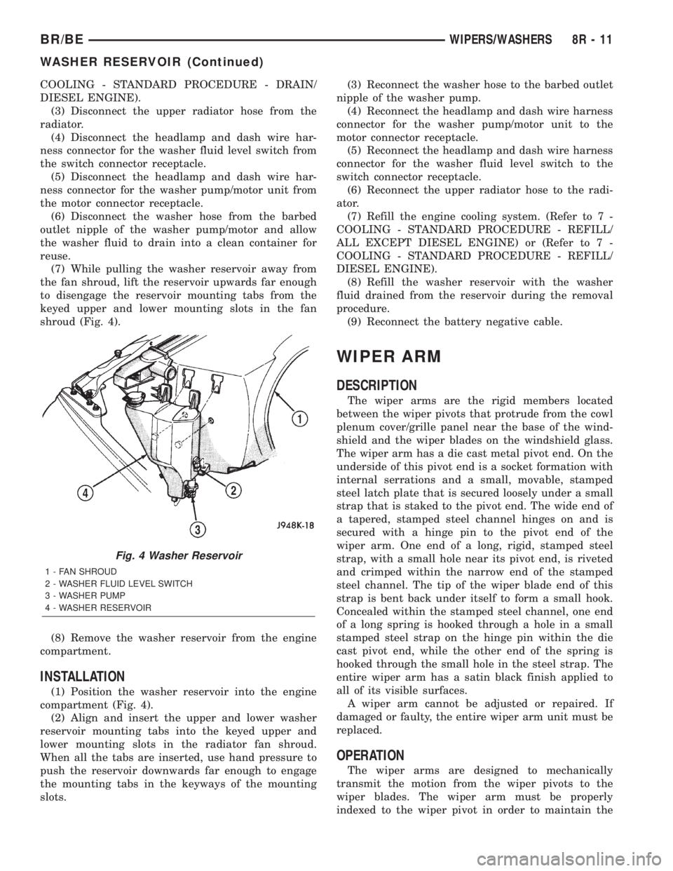
shroud (Fig. 4).
(8) Remove the washer reservoir from the engine
compartment.
INSTALLATION
(1) Position the washer reservoir into the engine
compartment (Fig. 4).
(2) Align and insert the upper and lower washer
reservoir mounting tabs into the keyed upper and
lower mounting slots in the radiator fan shroud.
When all the tabs are inserted, use hand pressure to
push the reservoir downwards far enough to engage
the mounting tabs in the keyways of the mounting
slots.(3) Reconnect the washer hose to the barbed outlet
nipple of the washer pump.
(4) Reconnect the headlamp and dash wire harness
connector for the washer pump/motor unit to the
motor connector receptacle.
(5) Reconnect the headlamp and dash wire harness
connector for the washer fluid level switch to the
switch connector receptacle.
(6) Reconnect the upper radiator hose to the radi-
ator.
(7) Refill the engine cooling system. (Refer to 7 -
COOLING - STANDARD PROCEDURE - REFILL/
ALL EXCEPT DIESEL ENGINE) or (Refer to 7 -
COOLING - STANDARD PROCEDURE - REFILL/
DIESEL ENGINE).
(8) Refill the washer reservoir with the washer
fluid drained from the reservoir during the removal
procedure.
(9) Reconnect the battery negative cable.
WIPER ARM
DESCRIPTION
The wiper arms are the rigid members located
between the wiper pivots that protrude from the cowl
plenum cover/grille panel near the base of the wind-
shield and the wiper blades on the windshield glass.
The wiper arm has a die cast metal pivot end. On the
underside of this pivot end is a socket formation with
internal serrations and a small, movable, stamped
steel latch plate that is secured loosely under a small
strap that is staked to the pivot end. The wide end of
a tapered, stamped steel channel hinges on and is
secured with a hinge pin to the pivot end of the
wiper arm. One end of a long, rigid, stamped steel
strap, with a small hole near its pivot end, is riveted
and crimped within the narrow end of the stamped
steel channel. The tip of the wiper blade end of this
strap is bent back under itself to form a small hook.
Concealed within the stamped steel channel, one end
of a long spring is hooked through a hole in a small
stamped steel strap on the hinge pin within the die
cast pivot end, while the other end of the spring is
hooked through the small hole in the steel strap. The
entire wiper arm has a satin black finish applied to
all of its visible surfaces.
A wiper arm cannot be adjusted or repaired. If
damaged or faulty, the entire wiper arm unit must be
replaced.
OPERATION
The wiper arms are designed to mechanically
transmit the motion from the wiper pivots to the
wiper blades. The wiper arm must be properly
indexed to the wiper pivot in order to maintain the
Fig. 4 Washer Reservoir
1 - FAN SHROUD
2 - WASHER FLUID LEVEL SWITCH
3 - WASHER PUMP
4 - WASHER RESERVOIR
BR/BEWIPERS/WASHERS 8R - 11
WASHER RESERVOIR (Continued)
Page 1186 of 2255
(6) Prime oil pump by squirting oil in the oil filter
mounting hole and filling the J-trap of the front tim-
ing cover. When oil is running out, install oil filter
that has been filled with oil.
(7) Install water pump and housing assembly
using new o-ring (Refer to 7 - COOLING/ENGINE/
WATER PUMP - INSTALLATION).
(8) Install generator, air pump, and bracket assem-
bly.
(9) Install A/C compressor (Refer to 24 - HEATING
& AIR CONDITIONING/PLUMBING/A/C COM-
PRESSOR - INSTALLATION).
(10) (10) Install the radiator fan (Refer to 7 -
COOLING/ENGINE/RADIATOR FAN - INSTALLA-
TION).
(11) Position the fan shroud and install the bolts.
Tighten the bolts to 11 N´m (95 in. lbs.) torque.
(12) Install the serpentine belt (Refer to 7 - COOL-
ING/ACCESSORY DRIVE/DRIVE BELTS - INSTAL-
LATION).
(13) Fill cooling system (Refer to 7 - COOLING -
STANDARD PROCEDURE).
(14) Connect the negative cable to the battery.
(15) Road test vehicle and check for leaks.
TIMING BELT/CHAIN AND
SPROCKETS
REMOVAL
(1) Remove timing chain cover and gasket using
extreme caution to avoid damaging oil pan gasket
(Refer to 9 - ENGINE/VALVE TIMING/TIMING
BELT / CHAIN COVER(S) - REMOVAL).
(2) Aline camshaft and crankshaft centerline.
Remove camshaft sprocket attaching bolt and remove
timing chain and camshaft sprockets.
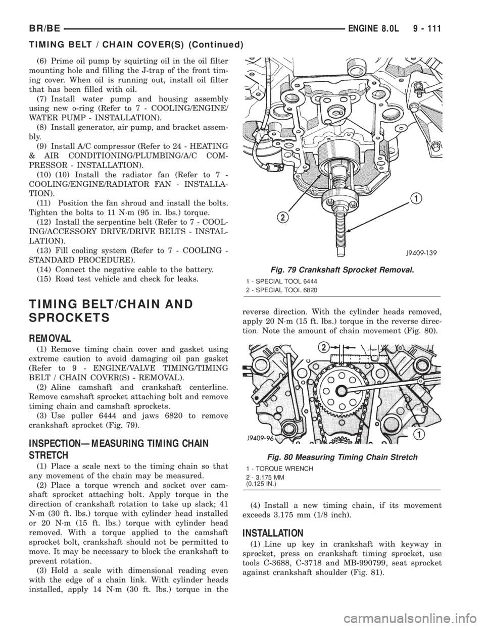
(3) Use puller 6444 and jaws 6820 to remove
crankshaft sprocket (Fig. 79).
INSPECTIONÐMEASURING TIMING CHAIN
STRETCH
(1) Place a scale next to the timing chain so that
any movement of the chain may be measured.
(2) Place a torque wrench and socket over cam-
shaft sprocket attaching bolt. Apply torque in the
direction of crankshaft rotation to take up slack; 41
N´m (30 ft. lbs.) torque with cylinder head installed
or 20 N´m (15 ft. lbs.) torque with cylinder head
removed. With a torque applied to the camshaft
sprocket bolt, crankshaft should not be permitted to
move. It may be necessary to block the crankshaft to
prevent rotation.
(3) Hold a scale with dimensional reading even
with the edge of a chain link. With cylinder heads
installed, apply 14 N´m (30 ft. lbs.) torque in thereverse direction. With the cylinder heads removed,
apply 20 N´m (15 ft. lbs.) torque in the reverse direc-
tion. Note the amount of chain movement (Fig. 80).
(4) Install a new timing chain, if its movement
exceeds 3.175 mm (1/8 inch).
INSTALLATION
(1) Line up key in crankshaft with keyway in
sprocket, press on crankshaft timing sprocket, use
tools C-3688, C-3718 and MB-990799, seat sprocket
against crankshaft shoulder (Fig. 81).
Fig. 79 Crankshaft Sprocket Removal.
1 - SPECIAL TOOL 6444
2 - SPECIAL TOOL 6820
Fig. 80 Measuring Timing Chain Stretch
1 - TORQUE WRENCH
2 - 3.175 MM
(0.125 IN.)
BR/BEENGINE 8.0L 9 - 111
TIMING BELT / CHAIN COVER(S) (Continued)
Page 1262 of 2255
(7) Position the charge air cooler inlet pipe to the
turbocharger. With the clamp in position, tighten the
clamp nut to 8 N´m (72 in. lbs.) torque.
(8) Position the air inlet hose to the turbocharger
(Fig. 170). Tighten the clamp to 8 N´m (72 in. lbs.)
torque.
(9) Raise vehicle on hoist.
(10) Connect the exhaust pipe to the turbocharger
(Fig. 169) and tighten the bolts to 34 N´m (25 ft. lbs.)
torque.
(11) Lower the vehicle.
(12) Connect the battery negative cables.
(13) Start the engine to check for leaks.
VALVE TIMING
STANDARD PROCEDURE - TIMING
VERIFICATION
(1) Remove the cylinder head cover.
(2) Remove fuel injector from cylinder number 1.
(3) Remove the crankcase breather from the gear
housing cover.
(4) Using Special Tool 7471B rotate the engine
until the timing mark on the fuel pump gear is
aligned with the TDC mark on the gear housing
cover.
(5) Using a 8 in.x 1/4 in. dowel rod inserted into
cylinder number 1, rock the crankshaft back and
forth to verify piston number 1 is at TDC.
(6) With piston number 1 at TDC the timing mark
on the fuel pump gear should be aligned with the
TDC mark on the gear housing cover. If marks do not
line up, remove the gear housing cover.
(7) With cylinder number still at TDC, inspect the
keyway on the crankshaft gear for proper alignment
(12 o'clock position).
(8) If the keyway is not at 12 o'clock position
replace the crankshaft gear assembly.
(9) If the keyway is at 12 o'clock position, verify
timing mark alignment between the camshaft gear,
crankshaft gear and the fuel pump gear, if not
aligned inspect keyway on camshaft gear.
(10) Inspect keyway on camshaft gear for proper
alignment with the key in the camshaft, if alignment
is off replace the camshaft/gear assembly.
(11) If timing marks alignment is off and no dam-
age is found at either the crankshaft or camshaft
gear keyways, realign timing marks as necessary.
GEAR HOUSING
REMOVAL
(1) Disconnect the battery negative cables.
(2) Raise vehicle on hoist.(3) Partially drain engine coolant into container
suitable for re-use (Refer to 7 - COOLING - STAN-
DARD PROCEDURE).
(4) Lower vehicle.
(5) Remove radiator upper hose.
(6) Disconnect coolant recovery bottle hose from
radiator filler neck and lift bottle off of fan shroud.
(7) Disconnect windshield washer pump supply
hose and electrical connections and lift washer bottle
off of fan shroud.
(8) Remove the fan shroud-to-radiator mounting
bolts.
(9) Remove viscous fan/drive assembly (Refer to 7 -
COOLING/ENGINE/RADIATOR FAN - REMOVAL).
(10) Remove the accessory drive belt (Refer to 7 -
COOLING/ACCESSORY DRIVE/DRIVE BELTS -
REMOVAL).
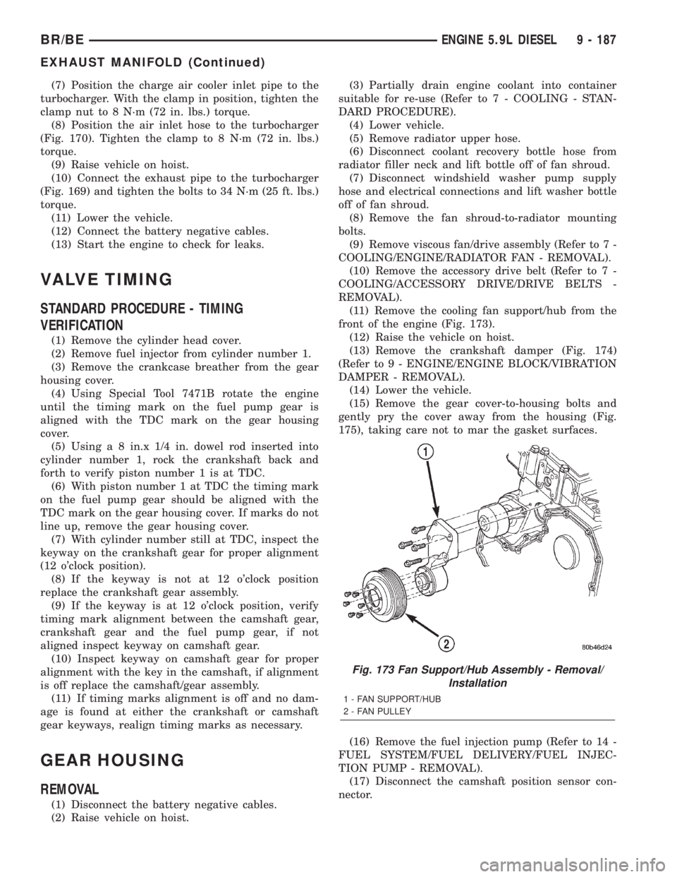
(11) Remove the cooling fan support/hub from the
front of the engine (Fig. 173).
(12) Raise the vehicle on hoist.
(13) Remove the crankshaft damper (Fig. 174)
(Refer to 9 - ENGINE/ENGINE BLOCK/VIBRATION
DAMPER - REMOVAL).
(14) Lower the vehicle.
(15) Remove the gear cover-to-housing bolts and
gently pry the cover away from the housing (Fig.
175), taking care not to mar the gasket surfaces.
(16) Remove the fuel injection pump (Refer to 14 -
FUEL SYSTEM/FUEL DELIVERY/FUEL INJEC-
TION PUMP - REMOVAL).
(17) Disconnect the camshaft position sensor con-
nector.
Fig. 173 Fan Support/Hub Assembly - Removal/
Installation
1 - FAN SUPPORT/HUB
2 - FAN PULLEY
BR/BEENGINE 5.9L DIESEL 9 - 187
EXHAUST MANIFOLD (Continued)
Page 1302 of 2255
(4) Connect the 0-414 kPa (0-60 psi) fuel pressure
test gauge (from Gauge Set 5069) to the test port on
the appropriate Adaptor Tool.The DRBtIII Scan
Tool along with the PEP module, the 500 psi
pressure transducer, and the transducer-to-test
port adapter may also be used in place of the
fuel pressure gauge.
The fittings on both tools must be in good
condition and free from any small leaks before
performing the proceeding test.
(5) Start engine and bring to normal operating
temperature.
(6) Observe test gauge. Normal operating pressure
should be 339 kPa +/±34 kPa (49.2 psi +/±5 psi).
(7) Shut engine off.
(8) Pressure should not fall below30 psi for five
minutes.
(9) If pressure falls below 30 psi, it must be deter-
mined if a fuel injector, the check valve within the
fuel pump module, or a fuel tube/line is leaking.
(10) Again, start engine and bring to normal oper-
ating temperature.
(11) Shut engine off.
(12)Testing for fuel injector or fuel rail leak-
age:Clamp off the rubber hose portion of Adaptor
Tool between the fuel rail and the test port ªTº on
Adapter Tool. If pressure now holds at or above 30
psi, a fuel injector or the fuel rail is leaking.
(13)Testing for fuel pump check valve, filter/
regulator check valve or fuel tube/line leakage:
Clamp off the rubber hose portion of Adaptor Tool
between the vehicle fuel line and test port ªTº on
Adapter Tool. If pressure now holds at or above 30
psi, a leak may be found at a fuel tube/line. If no
leaks are found at fuel tubes or lines, one of the
check valves in either the electric fuel pump or filter/
regulator may be leaking.
Note: A quick loss of pressure usually indicates a
defective check valve in the filter/regulator. A slow
loss of pressure usually indicates a defective check
valve in the electric fuel pump.
The electric fuel pump is not serviced separately.
Replace the fuel pump module assembly. The filter/
regulator may be replaced separately on certain
applications. Refer to Fuel Filter/Fuel Pressure Reg-
ulator Removal/Installation for additional informa-
tion.
STANDARD PROCEDURE - FUEL SYSTEM
PRESSURE RELEASE
Use following procedure if the fuel injector
rail is, or is not equipped with a fuel pressure
test port.
(1) Remove fuel fill cap.(2) Remove fuel pump relay from Power Distribu-
tion Center (PDC). For location of relay, refer to label
on underside of PDC cover.
(3) Start and run engine until it stalls.
(4) Attempt restarting engine until it will no
longer run.
(5) Turn ignition key to OFF position.
CAUTION: Steps 1, 2, 3 and 4 must be performed to
relieve high pressure fuel from within fuel rail. Do
not attempt to use following steps to relieve this
pressure as excessive fuel will be forced into a cyl-
inder chamber.
(6) Unplug connector from any fuel injector.
(7) Attach one end of a jumper wire with alligator
clips (18 gauge or smaller) to either injector terminal.
(8) Connect other end of jumper wire to positive
side of battery.
(9) Connect one end of a second jumper wire to
remaining injector terminal.
CAUTION: Powering an injector for more than a few
seconds will permanently damage the injector.
(10) Momentarily touch other end of jumper wire
to negative terminal of battery for no more than a
few seconds.
(11) Place a rag or towel below fuel line quick-con-
nect fitting at fuel rail.
(12) Disconnect quick-connect fitting at fuel rail.
Refer to Quick-Connect Fittings.
(13) Return fuel pump relay to PDC.
(14) One or more Diagnostic Trouble Codes (DTC's)
may have been stored in PCM memory due to fuel
pump relay removal. The DRBtscan tool must be
used to erase a DTC.
SPECIFICATIONS
SPECIFICATIONS - FUEL SYSTEM PRESSURE -
GAS ENGINES
All Gasoline Powered Engines:339 kPa 34
kPa (49.2 psi 5 psi)
BR/BEFUEL DELIVERY - GASOLINE 14 - 3
FUEL DELIVERY - GASOLINE (Continued)
Page 1310 of 2255
WARNING: BEFORE PROCEEDING TO NEXT STEP,
NOTE THE FUEL PUMP WILL BE ACTIVATED AND
SYSTEM PRESSURE WILL BE PRESENT. THIS WILL
OCCUR AFTER CONNECTING TEST LEADS FROM
LCS ADAPTER INTO FUEL PUMP RELAY CAVITIES.
THE FUEL PUMP WILL OPERATE EVEN WITH IGNI-
TION KEY IN OFF POSITION. BEFORE ATTACHING
TEST LEADS, BE SURE ALL FUEL LINES AND
FUEL SYSTEM COMPONENTS ARE CONNECTED.
CAUTION: To prevent possible damage to the vehi-
cle electrical system and LCS adapter, the test
leads must be connected into relay cavities exactly
as shown in following steps.
Depending upon vehicle model, year or engine con-
figuration, three different types of relays may be
used: Type-1, type-2 and type±3.
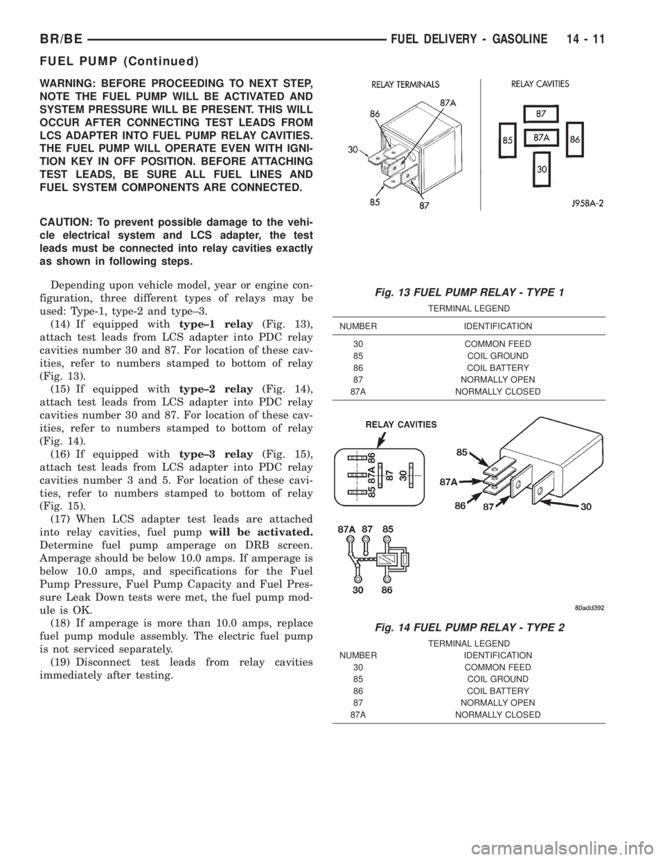
(14) If equipped withtype±1 relay(Fig. 13),
attach test leads from LCS adapter into PDC relay
cavities number 30 and 87. For location of these cav-
ities, refer to numbers stamped to bottom of relay
(Fig. 13).
(15) If equipped withtype±2 relay(Fig. 14),
attach test leads from LCS adapter into PDC relay
cavities number 30 and 87. For location of these cav-
ities, refer to numbers stamped to bottom of relay
(Fig. 14).
(16) If equipped withtype±3 relay(Fig. 15),
attach test leads from LCS adapter into PDC relay
cavities number 3 and 5. For location of these cavi-
ties, refer to numbers stamped to bottom of relay
(Fig. 15).
(17) When LCS adapter test leads are attached
into relay cavities, fuel pumpwill be activated.
Determine fuel pump amperage on DRB screen.
Amperage should be below 10.0 amps. If amperage is
below 10.0 amps, and specifications for the Fuel
Pump Pressure, Fuel Pump Capacity and Fuel Pres-
sure Leak Down tests were met, the fuel pump mod-
ule is OK.
(18) If amperage is more than 10.0 amps, replace
fuel pump module assembly. The electric fuel pump
is not serviced separately.
(19) Disconnect test leads from relay cavities
immediately after testing.
Fig. 13 FUEL PUMP RELAY - TYPE 1
TERMINAL LEGEND
NUMBER IDENTIFICATION
30 COMMON FEED
85 COIL GROUND
86 COIL BATTERY
87 NORMALLY OPEN
87A NORMALLY CLOSED
Fig. 14 FUEL PUMP RELAY - TYPE 2
TERMINAL LEGEND
NUMBER IDENTIFICATION
30 COMMON FEED
85 COIL GROUND
86 COIL BATTERY
87 NORMALLY OPEN
87A NORMALLY CLOSED
BR/BEFUEL DELIVERY - GASOLINE 14 - 11
FUEL PUMP (Continued)
Page 1339 of 2255
CAUTION: Before tightening sensor mounting bolt,
be sure sensor is completely flush to cylinder block
(Fig. 28). If sensor is not flush, damage to sensor
mounting tang may result.
(3) Install mounting bolt and tighten to 8 N´m (70
in. lbs.) torque.
(4) Connect sensor pigtail harness to main engine
wiring harness
(5) Install new plastic tie strap (Fig. 27) to secure
sensor pigtail harness to side of engine block. Thread
tie strap through casting hole on cylinder block.
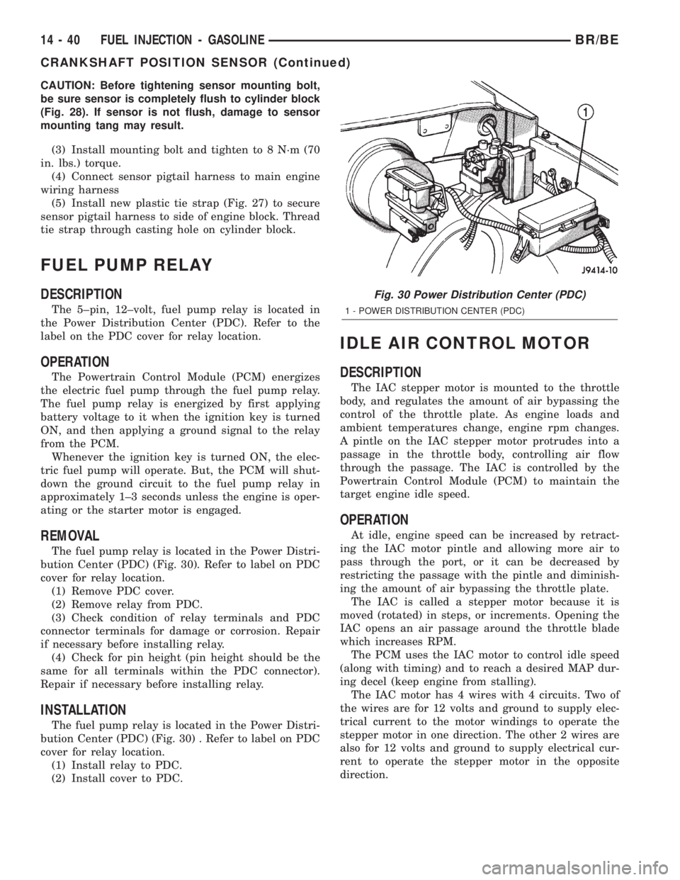
FUEL PUMP RELAY
DESCRIPTION
The 5±pin, 12±volt, fuel pump relay is located in
the Power Distribution Center (PDC). Refer to the
label on the PDC cover for relay location.
OPERATION
The Powertrain Control Module (PCM) energizes
the electric fuel pump through the fuel pump relay.
The fuel pump relay is energized by first applying
battery voltage to it when the ignition key is turned
ON, and then applying a ground signal to the relay
from the PCM.
Whenever the ignition key is turned ON, the elec-
tric fuel pump will operate. But, the PCM will shut-
down the ground circuit to the fuel pump relay in
approximately 1±3 seconds unless the engine is oper-
ating or the starter motor is engaged.
REMOVAL
The fuel pump relay is located in the Power Distri-
bution Center (PDC) (Fig. 30). Refer to label on PDC
cover for relay location.
(1) Remove PDC cover.
(2) Remove relay from PDC.
(3) Check condition of relay terminals and PDC
connector terminals for damage or corrosion. Repair
if necessary before installing relay.
(4) Check for pin height (pin height should be the
same for all terminals within the PDC connector).
Repair if necessary before installing relay.
INSTALLATION
The fuel pump relay is located in the Power Distri-
bution Center (PDC) (Fig. 30) . Refer to label on PDC
cover for relay location.
(1) Install relay to PDC.
(2) Install cover to PDC.
IDLE AIR CONTROL MOTOR
DESCRIPTION
The IAC stepper motor is mounted to the throttle
body, and regulates the amount of air bypassing the
control of the throttle plate. As engine loads and
ambient temperatures change, engine rpm changes.
A pintle on the IAC stepper motor protrudes into a
passage in the throttle body, controlling air flow
through the passage. The IAC is controlled by the
Powertrain Control Module (PCM) to maintain the
target engine idle speed.
OPERATION
At idle, engine speed can be increased by retract-
ing the IAC motor pintle and allowing more air to
pass through the port, or it can be decreased by
restricting the passage with the pintle and diminish-
ing the amount of air bypassing the throttle plate.
The IAC is called a stepper motor because it is
moved (rotated) in steps, or increments. Opening the
IAC opens an air passage around the throttle blade
which increases RPM.
The PCM uses the IAC motor to control idle speed
(along with timing) and to reach a desired MAP dur-
ing decel (keep engine from stalling).
The IAC motor has 4 wires with 4 circuits. Two of
the wires are for 12 volts and ground to supply elec-
trical current to the motor windings to operate the
stepper motor in one direction. The other 2 wires are
also for 12 volts and ground to supply electrical cur-
rent to operate the stepper motor in the opposite
direction.
Fig. 30 Power Distribution Center (PDC)
1 - POWER DISTRIBUTION CENTER (PDC)
14 - 40 FUEL INJECTION - GASOLINEBR/BE
CRANKSHAFT POSITION SENSOR (Continued)
Page 1366 of 2255
Voltage to operate the fuel heater element is sup-
plied from the ignition switch, through the fuel
heater relay (also refer to Fuel Heater Relay), to the
fuel temperature sensor and on to the fuel heater ele-
ment.
The heater element operates on 12 volts, 300 watts
at 0 degrees F. As temperature increases, power
requirements decrease.
A minimum of 7 volts is required to operate the
fuel heater. The resistance value of the heater ele-
ment is less than 1 ohm (cold) and up to 1000 ohms
warm.
TESTING
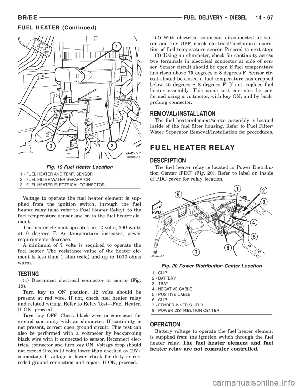
(1) Disconnect electrical connector at sensor (Fig.
19).
Turn key to ON position. 12 volts should be
present at red wire. If not, check fuel heater relay
and related wiring. Refer to Relay TestÐFuel Heater.
If OK, proceed.
Turn key OFF. Check black wire in connector for
ground continuity with an ohmmeter. If continuity is
not present, correct open ground circuit. This test can
also be performed with a voltmeter by backprobing
black wire with it connected to sensor. Reconnect elec-
trical connector and turn key ON. Voltage drop should
not exceed 2 volts (2 volts lower than checked at 12V+
connector). If voltage is lower, check for dirty or cor-
roded ground connection and repair. If OK, proceed.
(2) With electrical connector disconnected at sen-
sor and key OFF, check electrical/mechanical opera-
tion of fuel temperature sensor. Proceed to next step:
(3) Using an ohmmeter, check for continuity across
two terminals in electrical connector at side of sen-
sor. Sensor circuit should be open if fuel temperature
has risen above 75 degrees 8 degrees F. Sensor cir-
cuit should be closed if fuel temperature has dropped
below 45 degrees 8 degrees F. If not, replace fuel
heater assembly. This same test can also be per-
formed using a voltmeter, with key ON, and by back-
probing connector.
REMOVAL/INSTALLATION
The fuel heater/element/sensor assembly is located
inside of the fuel filter housing. Refer to Fuel Filter/
Water Separator Removal/Installation for procedures.
FUEL HEATER RELAY
DESCRIPTION
The fuel heater relay is located in Power Distribu-
tion Center (PDC) (Fig. 20). Refer to label on inside
of PDC cover for relay location.
OPERATION
Battery voltage to operate the fuel heater element
is supplied from the ignition switch through the fuel
heater relay.The fuel heater element and fuel
heater relay are not computer controlled.
Fig. 19 Fuel Heater Location
1 - FUEL HEATER AND TEMP. SENSOR
2 - FUEL FILTER/WATER SEPARATOR
3 - FUEL HEATER ELECTRICAL CONNECTOR
Fig. 20 Power Distribution Center Location
1 - CLIP
2 - BATTERY
3 - TRAY
4 - NEGATIVE CABLE
5 - POSITIVE CABLE
6 - CLIP
7 - FENDER INNER SHIELD
8 - POWER DISTRIBUTION CENTER
BR/BEFUEL DELIVERY - DIESEL 14 - 67
FUEL HEATER (Continued)