stop start DODGE RAM 2002 Service Owner's Guide
[x] Cancel search | Manufacturer: DODGE, Model Year: 2002, Model line: RAM, Model: DODGE RAM 2002Pages: 2255, PDF Size: 62.07 MB
Page 1428 of 2255
WORM THRUST BEARING PRELOAD
(1) Mount the gear carefully into a vise.
CAUTION: Do not overtighten the vise on the gear
case. This may affect the adjustment
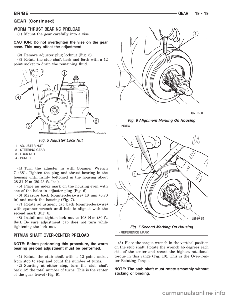
(2) Remove adjuster plug locknut (Fig. 5).
(3) Rotate the stub shaft back and forth with a 12
point socket to drain the remaining fluid.
(4) Turn the adjuster in with Spanner Wrench
C-4381. Tighten the plug and thrust bearing in the
housing until firmly bottomed in the housing about
28-31 N´m (20-23 ft. lbs.).
(5) Place an index mark on the housing even with
one of the holes in adjuster plug (Fig. 6).
(6) Measure back (counterclockwise) 18 mm (0.70
in) and mark the housing (Fig. 7).
(7) Rotate adjustment cap back (counterclockwise)
with spanner wrench until hole is aligned with the
second mark (Fig. 8).
(8) Install and tighten lock nut to 108 N´m (80 ft.
lbs.). Be sure adjustment cap does not turn while
tightening the lock nut.
PITMAN SHAFT OVER-CENTER PRELOAD
NOTE: Before performing this procedure, the worm
bearing preload adjustment must be performed.
(1) Rotate the stub shaft with a 12 point socket
from stop to stop and count the number of turns.
(2) Starting at either stop, turn the stub shaft
back 1/2 the total number of turns. This is the center
of the gear travel (Fig. 9).(3) Place the torque wrench in the vertical position
on the stub shaft. Rotate the wrench 45 degrees each
side of the center and record the highest rotational
torque in this range (Fig. 10). This is the Over-Cen-
ter Rotating Torque.
NOTE: The stub shaft must rotate smoothly without
sticking or binding.
Fig. 5 Adjuster Lock Nut
1 - ADJUSTER NUT
2 - STEERING GEAR
3 - LOCK NUT
4 - PUNCH
Fig. 6 Alignment Marking On Housing
1 - INDEX
Fig. 7 Second Marking On Housing
1 - REFERENCE MARK
BR/BEGEAR 19 - 19
GEAR (Continued)
Page 1444 of 2255
(3) Plug the return line port/ports at the pump.
(4) Position the return line/lines into a large con-
tainer to catch the fluid.
(5) While an assistant is filling the pump reservoir
start the engine.
(6) With the engine running at idle turn the wheel
back and forth.
NOTE: Do not contact or hold the wheel against the
steering stops.
(7) Run a quart of fluid through the system then
stop the engine and install the return line/lines.
(8) Fill the system with fluid and perform Steering
Pump Initial Operation, (Refer to 19 - STEERING/
PUMP - STANDARD PROCEDURE).
(9) Start the engine and run it for fifteen minutes
then stop the engine.
(10) Remove the return line/lines from the pump
and plug the pump port/ports.
(11) Pour fresh fluid into the reservoir and check
the draining fluid for contamination. If the fluid is
still contaminated, disassemble and clean the steer-
ing gear and flush the system again.
(12) Install the return line/lines and perform
Steering Pump Initial Operation, (Refer to 19 -
STEERING/PUMP - STANDARD PROCEDURE).
REMOVAL
REMOVAL - GASOLINE ENGINE
(1) Remove the serpentine drive belt, (Refer to 7 -
COOLING/ACCESSORY DRIVE/DRIVE BELTS -
REMOVAL) OR (Refer to 7 - COOLING/ACCESSORY
DRIVE/DRIVE BELTS - REMOVAL).
(2) Remove the hoses from the power steering
pump and cap the fittings.
(3) Remove battery ground cable and unthread
stud from cylinder head, do not remove from bracket.
(4) Loosen upper bracket bolt and remove the
lower bracket to engine block bolts.
(5) Pivot the pump assembly past the coolant tube.
(6) Remove the upper stud and remove upper bolt
from cylinder head.
(7) Remove steering pump and mounting bracket
from engine as an assembly.
(8) Remove the pump pulley with Puller C-4333, to
access pump attaching bolts, (Refer to 19 - STEER-
ING/PUMP/PULLEY - REMOVAL).
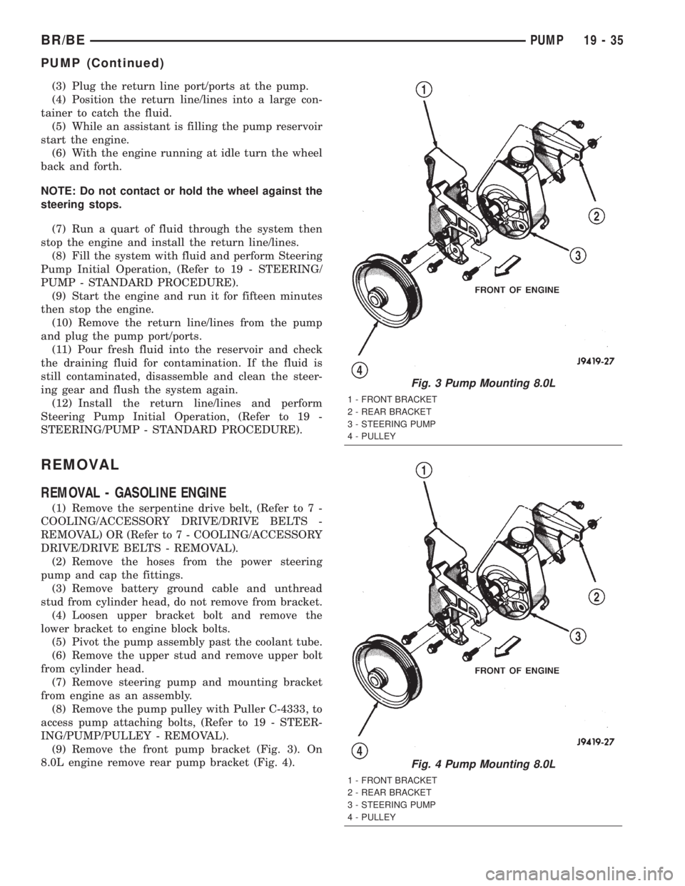
(9) Remove the front pump bracket (Fig. 3). On
8.0L engine remove rear pump bracket (Fig. 4).
Fig. 3 Pump Mounting 8.0L
1 - FRONT BRACKET
2 - REAR BRACKET
3 - STEERING PUMP
4 - PULLEY
Fig. 4 Pump Mounting 8.0L
1 - FRONT BRACKET
2 - REAR BRACKET
3 - STEERING PUMP
4 - PULLEY
BR/BEPUMP 19 - 35
PUMP (Continued)
Page 1478 of 2255
(5) If 1-2 synchro hub and sleeve were disassem-
bled for service, reassemble hub, sleeve, struts and
springs as follows:
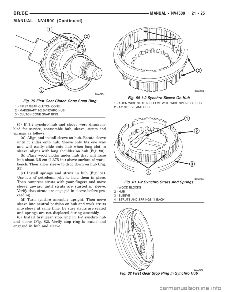
(a) Align and install sleeve on hub. Rotate sleeve
until it slides onto hub. Sleeve only fits one way
and will easily slide onto hub when long slot in
sleeve, aligns with long shoulder on hub (Fig. 80).
(b) Place wood blocks under hub that will raise
hub about 3.5 cm (1.375 in.) above surface of work-
bench. Then allow sleeve to drop down on hub (Fig.
81).
(c) Install springs and struts in hub (Fig. 81).
Use lots of petroleum jelly to hold them in place.
Then compress struts with your fingers and move
sleeve upward until struts are started in sleeve.
Verify that struts are engaged in sleeve before pro-
ceeding.
(d) Turn synchro assembly upright. Then move
sleeve into neutral position on hub and work struts
into sleeve at same time. Be sure struts are seated
and springs are not displaced during assembly.
(6) Install first gear stop ring in 1-2 synchro hub
and sleeve (Fig. 82). Verify stop ring is seated and
engaged in hub and sleeve.
Fig. 79 First Gear Clutch Cone Snap Ring
1 - FIRST GEAR CLUTCH CONE
2 - MAINSHAFT 1-2 SYNCHRO HUB
3 - CLUTCH CONE SNAP RING
Fig. 80 1-2 Synchro Sleeve On Hub
1 - ALIGN WIDE SLOT IN SLEEVE WITH WIDE SPLINE OF HUB
2 - 1-2 SLEEVE AND HUB
Fig. 81 1-2 Synchro Struts And Springs
1 - WOOD BLOCKS
2 - HUB
3 - SLEEVE
4 - STRUTS AND SPRINGS (4 EACH)
Fig. 82 First Gear Stop Ring In Synchro Hub
BR/BEMANUAL - NV4500 21 - 25
MANUAL - NV4500 (Continued)
Page 1482 of 2255
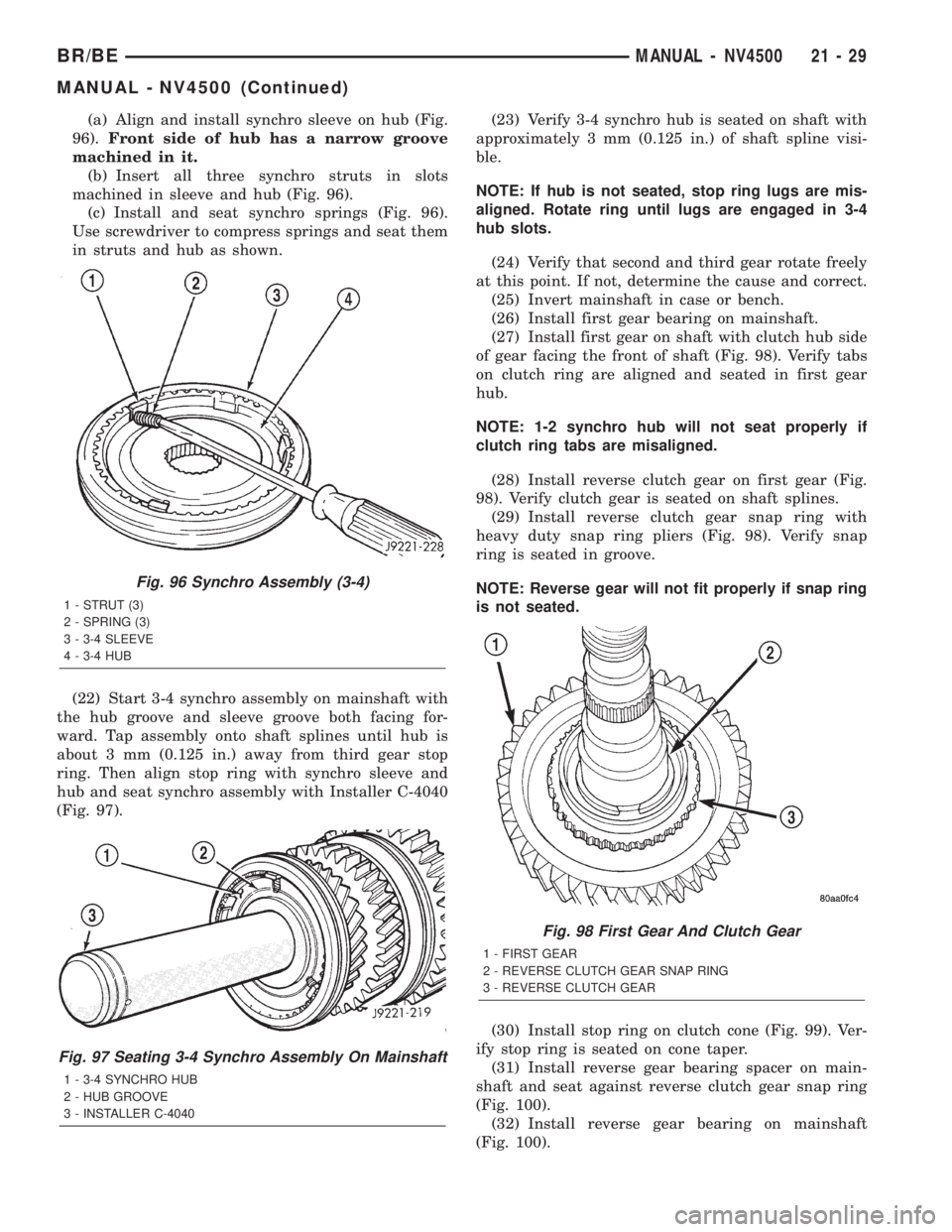
(a) Align and install synchro sleeve on hub (Fig.
96).Front side of hub has a narrow groove
machined in it.
(b) Insert all three synchro struts in slots
machined in sleeve and hub (Fig. 96).
(c) Install and seat synchro springs (Fig. 96).
Use screwdriver to compress springs and seat them
in struts and hub as shown.
(22) Start 3-4 synchro assembly on mainshaft with
the hub groove and sleeve groove both facing for-
ward. Tap assembly onto shaft splines until hub is
about 3 mm (0.125 in.) away from third gear stop
ring. Then align stop ring with synchro sleeve and
hub and seat synchro assembly with Installer C-4040
(Fig. 97).(23) Verify 3-4 synchro hub is seated on shaft with
approximately 3 mm (0.125 in.) of shaft spline visi-
ble.
NOTE: If hub is not seated, stop ring lugs are mis-
aligned. Rotate ring until lugs are engaged in 3-4
hub slots.
(24) Verify that second and third gear rotate freely
at this point. If not, determine the cause and correct.
(25) Invert mainshaft in case or bench.
(26) Install first gear bearing on mainshaft.
(27) Install first gear on shaft with clutch hub side
of gear facing the front of shaft (Fig. 98). Verify tabs
on clutch ring are aligned and seated in first gear
hub.
NOTE: 1-2 synchro hub will not seat properly if
clutch ring tabs are misaligned.
(28) Install reverse clutch gear on first gear (Fig.
98). Verify clutch gear is seated on shaft splines.
(29) Install reverse clutch gear snap ring with
heavy duty snap ring pliers (Fig. 98). Verify snap
ring is seated in groove.
NOTE: Reverse gear will not fit properly if snap ring
is not seated.
(30) Install stop ring on clutch cone (Fig. 99). Ver-
ify stop ring is seated on cone taper.
(31) Install reverse gear bearing spacer on main-
shaft and seat against reverse clutch gear snap ring
(Fig. 100).
(32) Install reverse gear bearing on mainshaft
(Fig. 100).
Fig. 96 Synchro Assembly (3-4)
1 - STRUT (3)
2 - SPRING (3)
3 - 3-4 SLEEVE
4 - 3-4 HUB
Fig. 97 Seating 3-4 Synchro Assembly On Mainshaft
1 - 3-4 SYNCHRO HUB
2 - HUB GROOVE
3 - INSTALLER C-4040
Fig. 98 First Gear And Clutch Gear
1 - FIRST GEAR
2 - REVERSE CLUTCH GEAR SNAP RING
3 - REVERSE CLUTCH GEAR
BR/BEMANUAL - NV4500 21 - 29
MANUAL - NV4500 (Continued)
Page 1488 of 2255
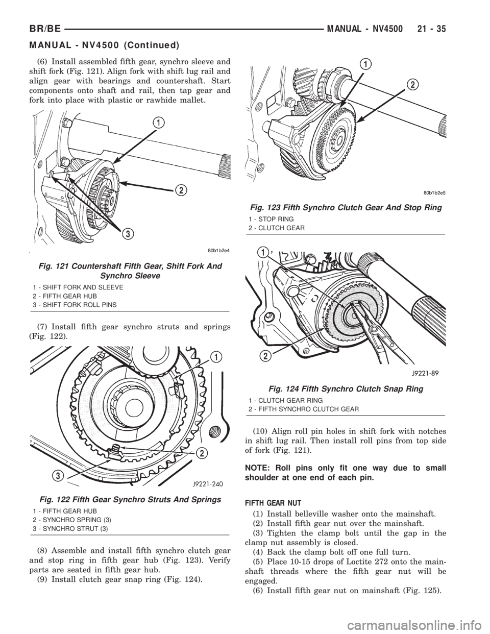
(6) Install assembled fifth gear, synchro sleeve and
shift fork (Fig. 121). Align fork with shift lug rail and
align gear with bearings and countershaft. Start
components onto shaft and rail, then tap gear and
fork into place with plastic or rawhide mallet.
(7) Install fifth gear synchro struts and springs
(Fig. 122).
(8) Assemble and install fifth synchro clutch gear
and stop ring in fifth gear hub (Fig. 123). Verify
parts are seated in fifth gear hub.
(9) Install clutch gear snap ring (Fig. 124).(10) Align roll pin holes in shift fork with notches
in shift lug rail. Then install roll pins from top side
of fork (Fig. 121).
NOTE: Roll pins only fit one way due to small
shoulder at one end of each pin.
FIFTH GEAR NUT
(1) Install belleville washer onto the mainshaft.
(2) Install fifth gear nut over the mainshaft.
(3) Tighten the clamp bolt until the gap in the
clamp nut assembly is closed.
(4) Back the clamp bolt off one full turn.
(5) Place 10-15 drops of Loctite 272 onto the main-
shaft threads where the fifth gear nut will be
engaged.
(6) Install fifth gear nut on mainshaft (Fig. 125).
Fig. 121 Countershaft Fifth Gear, Shift Fork And
Synchro Sleeve
1 - SHIFT FORK AND SLEEVE
2 - FIFTH GEAR HUB
3 - SHIFT FORK ROLL PINS
Fig. 122 Fifth Gear Synchro Struts And Springs
1 - FIFTH GEAR HUB
2 - SYNCHRO SPRING (3)
3 - SYNCHRO STRUT (3)
Fig. 123 Fifth Synchro Clutch Gear And Stop Ring
1 - STOP RING
2 - CLUTCH GEAR
Fig. 124 Fifth Synchro Clutch Snap Ring
1 - CLUTCH GEAR RING
2 - FIFTH SYNCHRO CLUTCH GEAR
BR/BEMANUAL - NV4500 21 - 35
MANUAL - NV4500 (Continued)
Page 1550 of 2255
DIAGNOSIS AND TESTING - PRELIMINARY
Two basic procedures are required. One procedure
for vehicles that are drivable and an alternate proce-
dure for disabled vehicles (will not back up or move
forward).
VEHICLE IS DRIVEABLE
(1) Check for transmission fault codes using DRBt
scan tool.
(2) Check fluid level and condition.
(3) Adjust throttle and gearshift linkage if com-
plaint was based on delayed, erratic, or harsh shifts.
(4) Road test and note how transmission upshifts,
downshifts, and engages.
(5) Perform hydraulic pressure test if shift prob-
lems were noted during road test.
(6) Perform air-pressure test to check clutch-band
operation.
VEHICLE IS DISABLED
(1) Check fluid level and condition.
(2) Check for broken or disconnected gearshift or
throttle linkage.
(3) Check for cracked, leaking cooler lines, or loose
or missing pressure-port plugs.
(4) Raise and support vehicle on safety stands,
start engine, shift transmission into gear, and note
following:
(a) If propeller shaft turns but wheels do not,
problem is with differential or axle shafts.(b) If propeller shaft does not turn and transmis-
sion is noisy, stop engine. Remove oil pan, and
check for debris. If pan is clear, remove transmis-
sion and check for damaged drive plate, converter,
oil pump, or input shaft.
(c) If propeller shaft does not turn and transmis-
sion is not noisy, perform hydraulic-pressure test to
determine if problem is hydraulic or mechanical.
DIAGNOSIS AND TESTING - ROAD TESTING
Before road testing, be sure the fluid level and con-
trol cable adjustments have been checked and
adjusted if necessary. Verify that diagnostic trouble
codes have been resolved.
Observe engine performance during the road test.
A poorly tuned engine will not allow accurate analy-
sis of transmission operation.
Operate the transmission in all gear ranges. Check
for shift variations and engine flare which indicates
slippage. Note if shifts are harsh, spongy, delayed,
early, or if part throttle downshifts are sensitive.
Slippage indicated by engine flare, usually means
clutch, band or overrunning clutch problems. If the
condition is advanced, an overhaul will be necessary
to restore normal operation.
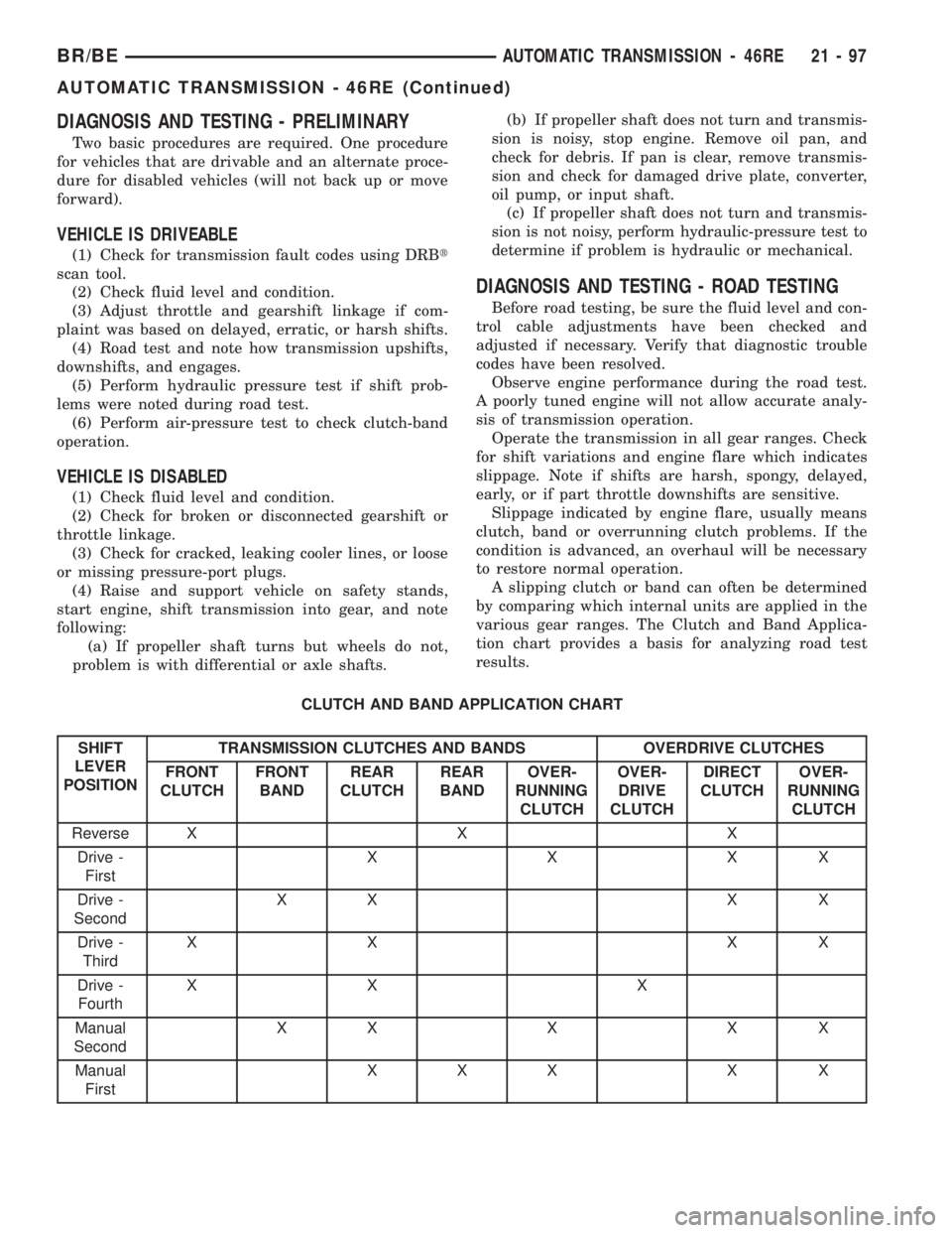
A slipping clutch or band can often be determined
by comparing which internal units are applied in the
various gear ranges. The Clutch and Band Applica-
tion chart provides a basis for analyzing road test
results.
CLUTCH AND BAND APPLICATION CHART
SHIFT
LEVER
POSITIONTRANSMISSION CLUTCHES AND BANDS OVERDRIVE CLUTCHES
FRONT
CLUTCHFRONT
BANDREAR
CLUTCHREAR
BANDOVER-
RUNNING
CLUTCHOVER-
DRIVE
CLUTCHDIRECT
CLUTCHOVER-
RUNNING
CLUTCH
Reverse X X X
Drive -
FirstXXXX
Drive -
SecondXX X X
Drive -
ThirdXX XX
Drive -
FourthXX X
Manual
SecondXXXXX
Manual
FirstXXX X X
BR/BEAUTOMATIC TRANSMISSION - 46RE 21 - 97
AUTOMATIC TRANSMISSION - 46RE (Continued)
Page 1722 of 2255
DIAGNOSIS AND TESTING - PRELIMINARY
Two basic procedures are required. One procedure
for vehicles that are drivable and an alternate proce-
dure for disabled vehicles (will not back up or move
forward).
VEHICLE IS DRIVEABLE
(1) Check for transmission fault codes using DRBt
scan tool.
(2) Check fluid level and condition.
(3) Adjust throttle and gearshift linkage if com-
plaint was based on delayed, erratic, or harsh shifts.
(4) Road test and note how transmission upshifts,
downshifts, and engages.
(5) Perform hydraulic pressure test if shift prob-
lems were noted during road test.
(6) Perform air-pressure test to check clutch-band
operation.
VEHICLE IS DISABLED
(1) Check fluid level and condition.
(2) Check for broken or disconnected gearshift or
throttle linkage.
(3) Check for cracked, leaking cooler lines, or loose
or missing pressure-port plugs.
(4) Raise and support vehicle on safety stands,
start engine, shift transmission into gear, and note
following:
(a) If propeller shaft turns but wheels do not,
problem is with differential or axle shafts.(b) If propeller shaft does not turn and transmis-
sion is noisy, stop engine. Remove oil pan, and
check for debris. If pan is clear, remove transmis-
sion and check for damaged drive plate, converter,
oil pump, or input shaft.
(c) If propeller shaft does not turn and transmis-
sion is not noisy, perform hydraulic-pressure test to
determine if problem is hydraulic or mechanical.
DIAGNOSIS AND TESTING - ROAD TESTING
Before road testing, be sure the fluid level and con-
trol cable adjustments have been checked and
adjusted if necessary. Verify that diagnostic trouble
codes have been resolved.
Observe engine performance during the road test.
A poorly tuned engine will not allow accurate analy-
sis of transmission operation.
Operate the transmission in all gear ranges. Check
for shift variations and engine flare which indicates
slippage. Note if shifts are harsh, spongy, delayed,
early, or if part throttle downshifts are sensitive.
Slippage indicated by engine flare, usually means
clutch, band or overrunning clutch problems. If the
condition is advanced, an overhaul will be necessary
to restore normal operation.
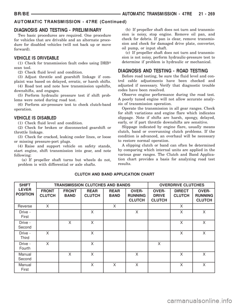
A slipping clutch or band can often be determined
by comparing which internal units are applied in the
various gear ranges. The Clutch and Band Applica-
tion chart provides a basis for analyzing road test
results.
CLUTCH AND BAND APPLICATION CHART
SHIFT
LEVER
POSITIONTRANSMISSION CLUTCHES AND BANDS OVERDRIVE CLUTCHES
FRONT
CLUTCHFRONT
BANDREAR
CLUTCHREAR
BANDOVER-
RUNNING
CLUTCHOVER-
DRIVE
CLUTCHDIRECT
CLUTCHOVER-
RUNNING
CLUTCH
Reverse X X X
Drive -
FirstXXXX
Drive -
SecondXX X X
Drive -
ThirdXX XX
Drive -
FourthXX X
Manual
SecondXXXXX
Manual
FirstXXX X X
BR/BEAUTOMATIC TRANSMISSION - 47RE 21 - 269
AUTOMATIC TRANSMISSION - 47RE (Continued)
Page 1970 of 2255
BRIGHT LIGHT LEAK TEST METHOD
Some water leaks in the luggage compartment can
be detected without water testing. Position the vehi-
cle in a brightly lit area. From inside the darkened
luggage compartment inspect around seals and body
seams. If necessary, have a helper direct a drop light
over the suspected leak areas around the luggage
compartment. If light is visible through a normally
sealed location, water could enter through the open-
ing.
PRESSURIZED LEAK TEST METHOD
When a water leak into the passenger compart-
ment cannot be detected by water testing, pressurize
the passenger compartment and soap test exterior of
the vehicle. To pressurize the passenger compart-
ment, close all doors and windows, start engine, and
set heater control to high blower in HEAT position. If
engine can not be started, connect a charger to the
battery to ensure adequate voltage to the blower.
With interior pressurized, apply dish detergent solu-
tion to suspected leak area on the exterior of the
vehicle. Apply detergent solution with spray device or
soft bristle brush. If soap bubbles occur at a body
seam, joint, seal or gasket, the leak entry point could
be at that location.
DIAGNOSIS AND TESTING - WIND NOISE
Wind noise is the result of most air leaks. Air leaks
can be caused by poor sealing, improper body compo-
nent alignment, body seam porosity, or missing plugs
in the engine compartment or door hinge pillar areas.
All body sealing points should be airtight in normal
driving conditions. Moving sealing surfaces will not
always seal airtight under all conditions. At times,
side glass or door seals will allow wind noise to be
noticed in the passenger compartment during highcross winds. Over compensating on door or glass
adjustments to stop wind noise that occurs under
severe conditions can cause premature seal wear and
excessive closing or latching effort. After a repair pro-
cedure has been performed, test vehicle to verify
noise has stopped before returning vehicle to use.
Wind noise can also be caused by improperly fitted
exterior moldings or body ornamentation. Loose
moldings can flutter, creating a buzzing or chattering
noise. An open cavity or protruding edge can create a
whistling or howling noise. Inspect the exterior of the
vehicle to verify that these conditions do not exist.
VISUAL INSPECTION BEFORE TESTS
Verify that floor and body plugs are in place and
body components are aligned and sealed. If compo-
nent alignment or sealing is necessary, refer to the
appropriate section of this group for proper proce-
dures.
ROAD TESTING WIND NOISE
(1) Drive the vehicle to verify the general location
of the wind noise.
(2) Apply 50 mm (2 in.) masking tape in 150 mm
(6 in.) lengths along weatherstrips, weld seams or
moldings. After each length is applied, drive the vehi-
cle. If noise goes away after a piece of tape is applied,
remove tape, locate, and repair defect.
POSSIBLE CAUSE OF WIND NOISE
²Moldings standing away from body surface can
catch wind and whistle.
²Gaps in sealed areas behind overhanging body
flanges can cause wind-rushing sounds.
²Misaligned movable components.
²Missing or improperly installed plugs in pillars.
²Weld burn through holes.
BR/BEBODY 23 - 3
BODY (Continued)
Page 2131 of 2255
CONTROLS
DIAGNOSIS AND TESTING - VACUUM SYSTEM
Vacuum control is used to operate the mode doors
in the heater-only and HVAC housings. Testing of the
heater-only and a/c heater mode control switch oper-
ation will determine if the vacuum, electrical, and
mechanical controls are functioning. However, it is
possible that a vacuum control system that operates
perfectly at engine idle (high engine vacuum) may
not function properly at high engine speeds or loads
(low engine vacuum). This can be caused by leaks in
the vacuum system, or by a faulty or improperly
installed vacuum check valve.
A vacuum system test will help to identify the
source of poor vacuum system performance or vac-
uum system leaks. Before starting this test, stop the
engine and make certain that the problem is not a
disconnected vacuum supply tube at the engine vac-
uum source or the vacuum reservoir.
Use an adjustable vacuum test set (Special Tool
C-3707) and a suitable vacuum pump to test the
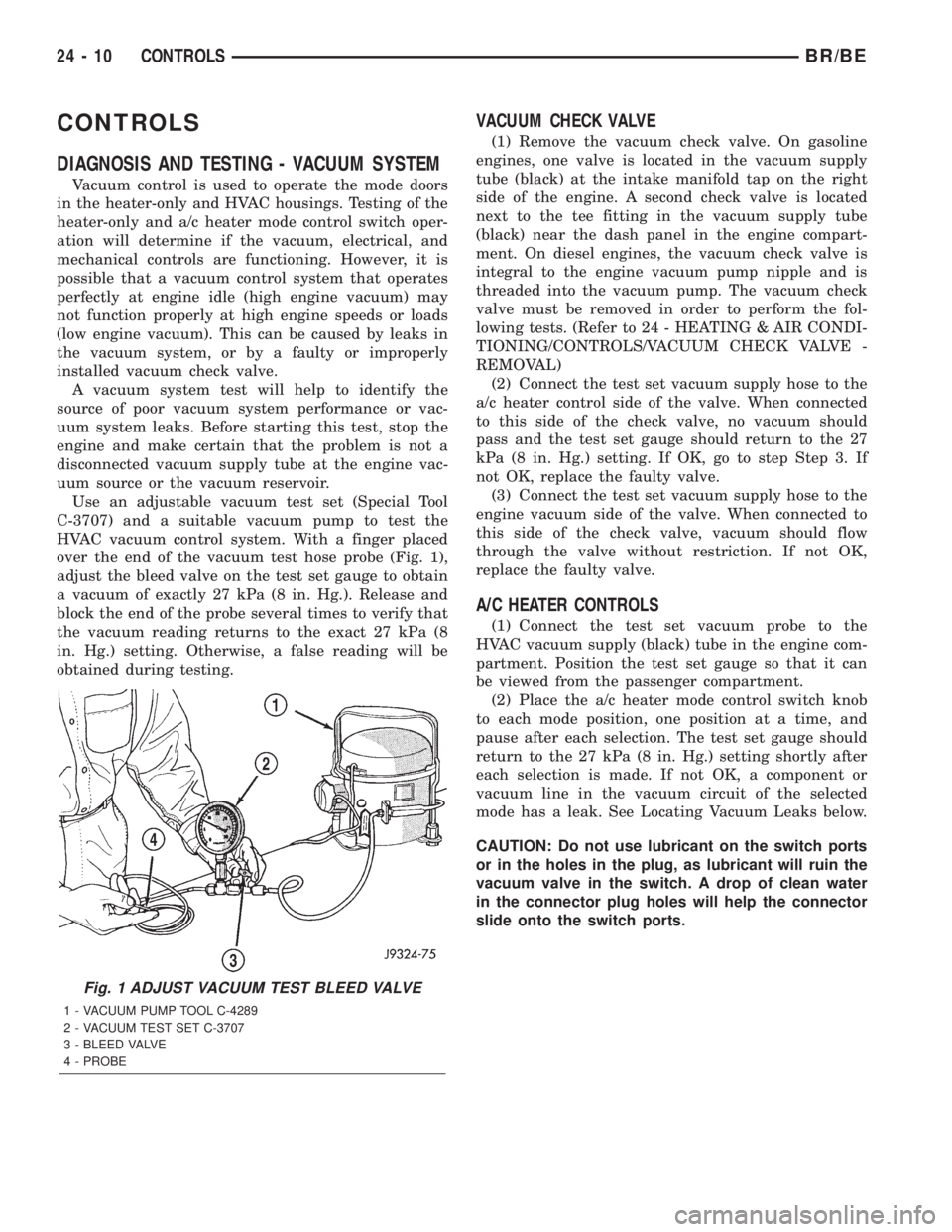
HVAC vacuum control system. With a finger placed
over the end of the vacuum test hose probe (Fig. 1),
adjust the bleed valve on the test set gauge to obtain
a vacuum of exactly 27 kPa (8 in. Hg.). Release and
block the end of the probe several times to verify that
the vacuum reading returns to the exact 27 kPa (8
in. Hg.) setting. Otherwise, a false reading will be
obtained during testing.
VACUUM CHECK VALVE
(1) Remove the vacuum check valve. On gasoline
engines, one valve is located in the vacuum supply
tube (black) at the intake manifold tap on the right
side of the engine. A second check valve is located
next to the tee fitting in the vacuum supply tube
(black) near the dash panel in the engine compart-
ment. On diesel engines, the vacuum check valve is
integral to the engine vacuum pump nipple and is
threaded into the vacuum pump. The vacuum check
valve must be removed in order to perform the fol-
lowing tests. (Refer to 24 - HEATING & AIR CONDI-
TIONING/CONTROLS/VACUUM CHECK VALVE -
REMOVAL)
(2) Connect the test set vacuum supply hose to the
a/c heater control side of the valve. When connected
to this side of the check valve, no vacuum should
pass and the test set gauge should return to the 27
kPa (8 in. Hg.) setting. If OK, go to step Step 3. If
not OK, replace the faulty valve.
(3) Connect the test set vacuum supply hose to the
engine vacuum side of the valve. When connected to
this side of the check valve, vacuum should flow
through the valve without restriction. If not OK,
replace the faulty valve.
A/C HEATER CONTROLS
(1) Connect the test set vacuum probe to the
HVAC vacuum supply (black) tube in the engine com-
partment. Position the test set gauge so that it can
be viewed from the passenger compartment.
(2) Place the a/c heater mode control switch knob
to each mode position, one position at a time, and
pause after each selection. The test set gauge should
return to the 27 kPa (8 in. Hg.) setting shortly after
each selection is made. If not OK, a component or
vacuum line in the vacuum circuit of the selected
mode has a leak. See Locating Vacuum Leaks below.
CAUTION: Do not use lubricant on the switch ports
or in the holes in the plug, as lubricant will ruin the
vacuum valve in the switch. A drop of clean water
in the connector plug holes will help the connector
slide onto the switch ports.
Fig. 1 ADJUST VACUUM TEST BLEED VALVE
1 - VACUUM PUMP TOOL C-4289
2 - VACUUM TEST SET C-3707
3 - BLEED VALVE
4 - PROBE
24 - 10 CONTROLSBR/BE
Page 2184 of 2255
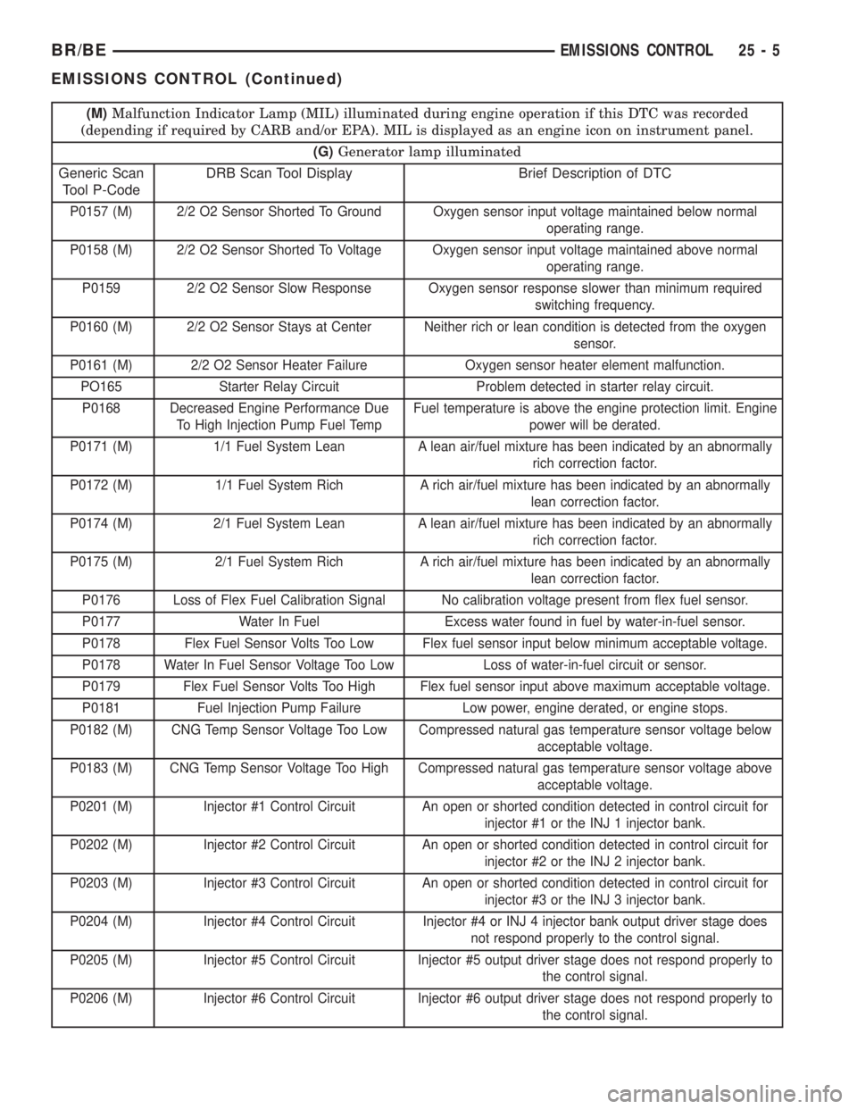
(M)Malfunction Indicator Lamp (MIL) illuminated during engine operation if this DTC was recorded
(depending if required by CARB and/or EPA). MIL is displayed as an engine icon on instrument panel.
(G)Generator lamp illuminated
Generic Scan
Tool P-CodeDRB Scan Tool Display Brief Description of DTC
P0157 (M) 2/2 O2 Sensor Shorted To Ground Oxygen sensor input voltage maintained below normal
operating range.
P0158 (M) 2/2 O2 Sensor Shorted To Voltage Oxygen sensor input voltage maintained above normal
operating range.
P0159 2/2 O2 Sensor Slow Response Oxygen sensor response slower than minimum required
switching frequency.
P0160 (M) 2/2 O2 Sensor Stays at Center Neither rich or lean condition is detected from the oxygen
sensor.
P0161 (M) 2/2 O2 Sensor Heater Failure Oxygen sensor heater element malfunction.
PO165 Starter Relay Circuit Problem detected in starter relay circuit.
P0168 Decreased Engine Performance Due
To High Injection Pump Fuel TempFuel temperature is above the engine protection limit. Engine
power will be derated.
P0171 (M) 1/1 Fuel System Lean A lean air/fuel mixture has been indicated by an abnormally
rich correction factor.
P0172 (M) 1/1 Fuel System Rich A rich air/fuel mixture has been indicated by an abnormally
lean correction factor.
P0174 (M) 2/1 Fuel System Lean A lean air/fuel mixture has been indicated by an abnormally
rich correction factor.
P0175 (M) 2/1 Fuel System Rich A rich air/fuel mixture has been indicated by an abnormally
lean correction factor.
P0176 Loss of Flex Fuel Calibration Signal No calibration voltage present from flex fuel sensor.
P0177 Water In Fuel Excess water found in fuel by water-in-fuel sensor.
P0178 Flex Fuel Sensor Volts Too Low Flex fuel sensor input below minimum acceptable voltage.
P0178 Water In Fuel Sensor Voltage Too Low Loss of water-in-fuel circuit or sensor.
P0179 Flex Fuel Sensor Volts Too High Flex fuel sensor input above maximum acceptable voltage.
P0181 Fuel Injection Pump Failure Low power, engine derated, or engine stops.
P0182 (M) CNG Temp Sensor Voltage Too Low Compressed natural gas temperature sensor voltage below
acceptable voltage.
P0183 (M) CNG Temp Sensor Voltage Too High Compressed natural gas temperature sensor voltage above
acceptable voltage.
P0201 (M) Injector #1 Control Circuit An open or shorted condition detected in control circuit for
injector #1 or the INJ 1 injector bank.
P0202 (M) Injector #2 Control Circuit An open or shorted condition detected in control circuit for
injector #2 or the INJ 2 injector bank.
P0203 (M) Injector #3 Control Circuit An open or shorted condition detected in control circuit for
injector #3 or the INJ 3 injector bank.
P0204 (M) Injector #4 Control Circuit Injector #4 or INJ 4 injector bank output driver stage does
not respond properly to the control signal.
P0205 (M) Injector #5 Control Circuit Injector #5 output driver stage does not respond properly to
the control signal.
P0206 (M) Injector #6 Control Circuit Injector #6 output driver stage does not respond properly to
the control signal.
BR/BEEMISSIONS CONTROL 25 - 5
EMISSIONS CONTROL (Continued)