fuel cap DODGE RAM 2002 Service Workshop Manual
[x] Cancel search | Manufacturer: DODGE, Model Year: 2002, Model line: RAM, Model: DODGE RAM 2002Pages: 2255, PDF Size: 62.07 MB
Page 1370 of 2255
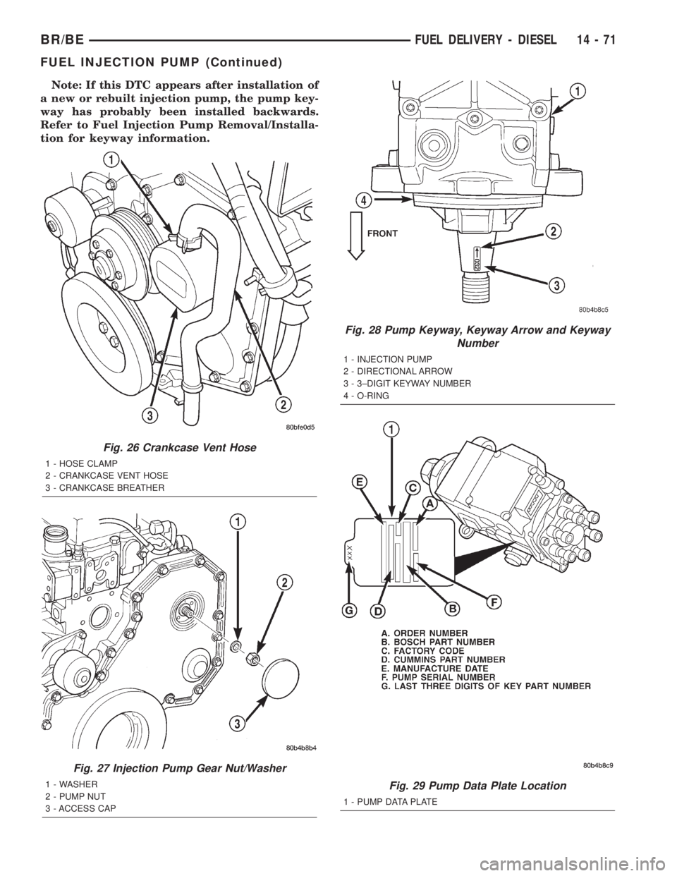
Note: If this DTC appears after installation of
a new or rebuilt injection pump, the pump key-
way has probably been installed backwards.
Refer to Fuel Injection Pump Removal/Installa-
tion for keyway information.
Fig. 26 Crankcase Vent Hose
1 - HOSE CLAMP
2 - CRANKCASE VENT HOSE
3 - CRANKCASE BREATHER
Fig. 27 Injection Pump Gear Nut/Washer
1 - WASHER
2 - PUMP NUT
3 - ACCESS CAP
Fig. 28 Pump Keyway, Keyway Arrow and Keyway
Number
1 - INJECTION PUMP
2 - DIRECTIONAL ARROW
3 - 3±DIGIT KEYWAY NUMBER
4 - O-RING
Fig. 29 Pump Data Plate Location
1 - PUMP DATA PLATE
BR/BEFUEL DELIVERY - DIESEL 14 - 71
FUEL INJECTION PUMP (Continued)
Page 1382 of 2255
REMOVAL
(1) Drain and remove fuel tank. Refer to Fuel
Tank Removal/Installation.
(2) Thoroughly clean area around tank module at
top of tank.
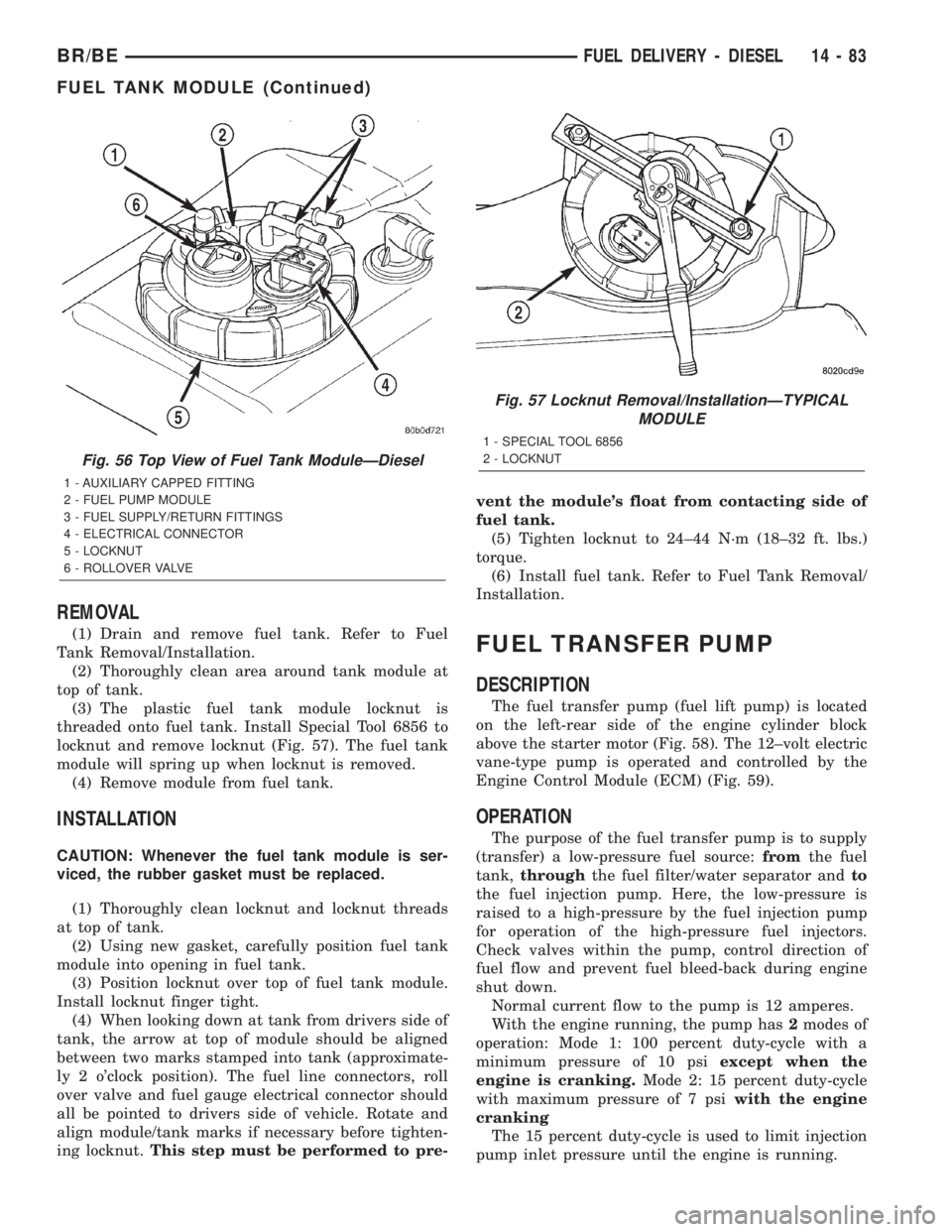
(3) The plastic fuel tank module locknut is
threaded onto fuel tank. Install Special Tool 6856 to
locknut and remove locknut (Fig. 57). The fuel tank
module will spring up when locknut is removed.
(4) Remove module from fuel tank.
INSTALLATION
CAUTION: Whenever the fuel tank module is ser-
viced, the rubber gasket must be replaced.
(1) Thoroughly clean locknut and locknut threads
at top of tank.
(2) Using new gasket, carefully position fuel tank
module into opening in fuel tank.
(3) Position locknut over top of fuel tank module.
Install locknut finger tight.
(4) When looking down at tank from drivers side of
tank, the arrow at top of module should be aligned
between two marks stamped into tank (approximate-
ly 2 o'clock position). The fuel line connectors, roll
over valve and fuel gauge electrical connector should
all be pointed to drivers side of vehicle. Rotate and
align module/tank marks if necessary before tighten-
ing locknut.This step must be performed to pre-vent the module's float from contacting side of
fuel tank.
(5) Tighten locknut to 24±44 N´m (18±32 ft. lbs.)
torque.
(6) Install fuel tank. Refer to Fuel Tank Removal/
Installation.
FUEL TRANSFER PUMP
DESCRIPTION
The fuel transfer pump (fuel lift pump) is located
on the left-rear side of the engine cylinder block
above the starter motor (Fig. 58). The 12±volt electric
vane-type pump is operated and controlled by the
Engine Control Module (ECM) (Fig. 59).
OPERATION
The purpose of the fuel transfer pump is to supply
(transfer) a low-pressure fuel source:fromthe fuel
tank,throughthe fuel filter/water separator andto
the fuel injection pump. Here, the low-pressure is
raised to a high-pressure by the fuel injection pump
for operation of the high-pressure fuel injectors.
Check valves within the pump, control direction of
fuel flow and prevent fuel bleed-back during engine
shut down.
Normal current flow to the pump is 12 amperes.
With the engine running, the pump has2modes of
operation: Mode 1: 100 percent duty-cycle with a
minimum pressure of 10 psiexcept when the
engine is cranking.Mode 2: 15 percent duty-cycle
with maximum pressure of 7 psiwith the engine
cranking
The 15 percent duty-cycle is used to limit injection
pump inlet pressure until the engine is running.
Fig. 56 Top View of Fuel Tank ModuleÐDiesel
1 - AUXILIARY CAPPED FITTING
2 - FUEL PUMP MODULE
3 - FUEL SUPPLY/RETURN FITTINGS
4 - ELECTRICAL CONNECTOR
5 - LOCKNUT
6 - ROLLOVER VALVE
Fig. 57 Locknut Removal/InstallationÐTYPICAL
MODULE
1 - SPECIAL TOOL 6856
2 - LOCKNUT
BR/BEFUEL DELIVERY - DIESEL 14 - 83
FUEL TANK MODULE (Continued)
Page 1384 of 2255
Refer to Fuel Transfer Pump Description/Operation
for an operational description of transfer pump.
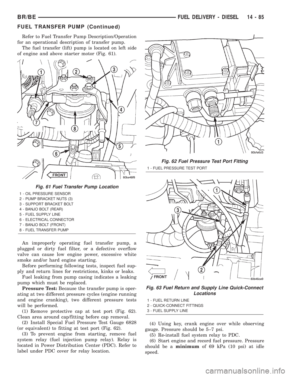
The fuel transfer (lift) pump is located on left side
of engine and above starter motor (Fig. 61).
An improperly operating fuel transfer pump, a
plugged or dirty fuel filter, or a defective overflow
valve can cause low engine power, excessive white
smoke and/or hard engine starting.
Before performing following tests, inspect fuel sup-
ply and return lines for restrictions, kinks or leaks.
Fuel leaking from pump casing indicates a leaking
pump which must be replaced.
Pressure Test:Because the transfer pump is oper-
ating at two different pressure cycles (engine running
and engine cranking), two different pressure tests
will be performed.
(1) Remove protective cap at test port (Fig. 62).
Clean area around cap/fitting before cap removal.
(2) Install Special Fuel Pressure Test Gauge 6828
(or equivalent) to fitting at test port (Fig. 62).
(3) To prevent engine from starting, remove fuel
system relay (fuel injection pump relay). Relay is
located in Power Distribution Center (PDC). Refer to
label under PDC cover for relay location.(4) Using key, crank engine over while observing
gauge. Pressure should be 5±7 psi.
(5) Re-install fuel system relay to PDC.
(6) Start engine and record fuel pressure. Pressure
should be aminimumof 69 kPa (10 psi) at idle
speed.
Fig. 61 Fuel Transfer Pump Location
1 - OIL PRESSURE SENSOR
2 - PUMP BRACKET NUTS (3)
3 - SUPPORT BRACKET BOLT
4 - BANJO BOLT (REAR)
5 - FUEL SUPPLY LINE
6 - ELECTRICAL CONNECTOR
7 - BANJO BOLT (FRONT)
8 - FUEL TRANSFER PUMP
Fig. 62 Fuel Pressure Test Port Fitting
1 - FUEL PRESSURE TEST PORT
Fig. 63 Fuel Return and Supply Line Quick-Connect
Locations
1 - FUEL RETURN LINE
2 - QUICK-CONNECT FITTINGS
3 - FUEL SUPPLY LINE
BR/BEFUEL DELIVERY - DIESEL 14 - 85
FUEL TRANSFER PUMP (Continued)
Page 1385 of 2255
(7) Because fuel pump relay was removed, a Diag-
nostic Trouble Code (DTC) may have been set. After
testing is completed, and relay has been installed,
use DRB scan tool to remove DTC.
Fuel Supply Restriction Test:
Due to very small vacuum specifications, the DRB
scan tool along with the Periphal Expansion Port
(PEP) Module and 0±15 psi transducer must be used.
(8) Verify transfer pump pressure is OK before
performing restriction test.
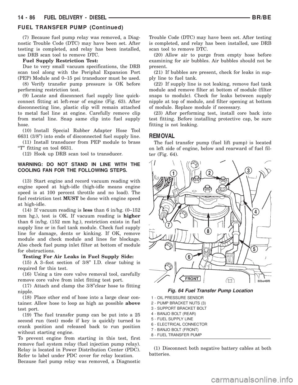
(9) Locate and disconnect fuel supply line quick-
connect fitting at left-rear of engine (Fig. 63). After
disconnecting line, plastic clip will remain attached
to metal fuel line at engine. Carefully remove clip
from metal line. Snap same clip into fuel supply
hose.
(10) Install Special Rubber Adapter Hose Tool
6631 (3/8º) into ends of disconnected fuel supply line.
(11) Install transducer from PEP module to brass
ªTº fitting on tool 6631.
(12) Hook up DRB scan tool to transducer.
WARNING: DO NOT STAND IN LINE WITH THE
COOLING FAN FOR THE FOLLOWING STEPS.
(13) Start engine and record vacuum reading with
engine speed at high-idle (high-idle means engine
speed is at 100 percent throttle and no load). The
fuel restriction testMUSTbe done with engine speed
at high-idle.
(14) If vacuum reading islessthan 6 in/hg. (0±152
mm hg.), test is OK. If vacuum reading ishigher
than 6 in/hg. (152 mm hg.), restriction exists in fuel
supply line or in fuel tank module. Check fuel supply
line for damage, dents or kinking. If OK, remove
module and check module and lines for blockage.
Also check fuel pump inlet filter at bottom of module
for obstructions.
Testing For Air Leaks in Fuel Supply Side:
(15) A 3±foot section of 3/8º I.D. clear tubing is
required for this test.
(16) Using a tire core valve removal tool, carefully
remove core valve from inlet fitting test port.
(17) Attach and clamp the 3/8ºclear hose to fitting
nipple.
(18) Place other end of hose into a large clear con-
tainer. Allow hose to loop as high as possibleabove
test port.
(19) The fuel transfer pump can be put into a 25
second run (test) mode if key is quickly turned to
crank position and released back to run position
without starting engine.
To prevent engine from starting in this test, first
remove fuel system relay (fuel injection pump relay).
Relay is located in Power Distribution Center (PDC).
Refer to label under PDC cover for relay location.
Because fuel pump relay was removed, a DiagnosticTrouble Code (DTC) may have been set. After testing
is completed, and relay has been installed, use DRB
scan tool to remove DTC.
(20) Allow air to purge from empty hose before
examining for air bubbles. Air bubbles should not be
present.
(21) If bubbles are present, check for leaks in sup-
ply line to fuel tank.
(22) If supply line is not leaking, remove fuel tank
module and remove filter at bottom of module (filter
snaps to module). Check for leaks between supply
nipple at top of module, and filter opening at bottom
of module. Replace module if necessary.
(23) After performing test, install core back into
test fitting. Before installing protective cap, be sure
fitting is not leaking.
REMOVAL
The fuel transfer pump (fuel lift pump) is located
on left side of engine, below and rearward of fuel fil-
ter (Fig. 64).
(1) Disconnect both negative battery cables at both
batteries.
Fig. 64 Fuel Transfer Pump Location
1 - OIL PRESSURE SENSOR
2 - PUMP BRACKET NUTS (3)
3 - SUPPORT BRACKET BOLT
4 - BANJO BOLT (REAR)
5 - FUEL SUPPLY LINE
6 - ELECTRICAL CONNECTOR
7 - BANJO BOLT (FRONT)
8 - FUEL TRANSFER PUMP
14 - 86 FUEL DELIVERY - DIESELBR/BE
FUEL TRANSFER PUMP (Continued)
Page 1398 of 2255
lines before opening up any fuel system component.
Always cover or cap any open fuel connections before
a fuel system repair is performed.
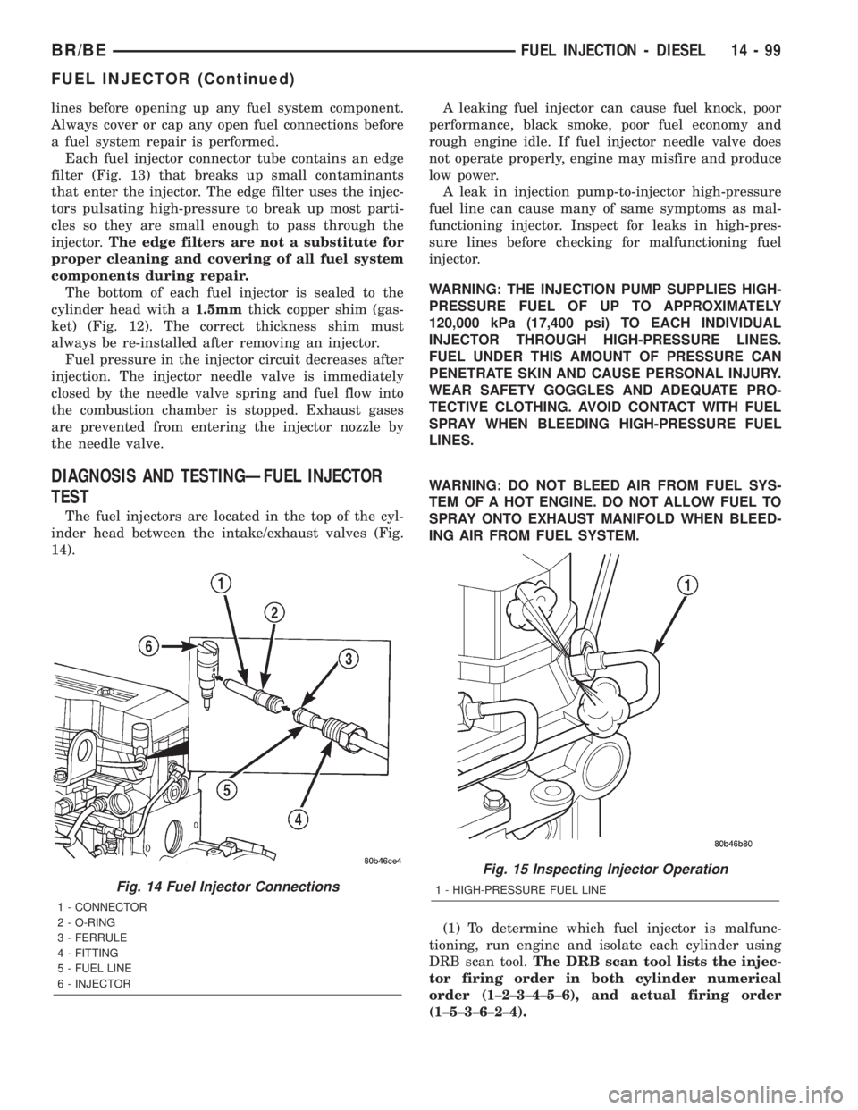
Each fuel injector connector tube contains an edge
filter (Fig. 13) that breaks up small contaminants
that enter the injector. The edge filter uses the injec-
tors pulsating high-pressure to break up most parti-
cles so they are small enough to pass through the
injector.The edge filters are not a substitute for
proper cleaning and covering of all fuel system
components during repair.
The bottom of each fuel injector is sealed to the
cylinder head with a1.5mmthick copper shim (gas-
ket) (Fig. 12). The correct thickness shim must
always be re-installed after removing an injector.
Fuel pressure in the injector circuit decreases after
injection. The injector needle valve is immediately
closed by the needle valve spring and fuel flow into
the combustion chamber is stopped. Exhaust gases
are prevented from entering the injector nozzle by
the needle valve.
DIAGNOSIS AND TESTINGÐFUEL INJECTOR
TEST
The fuel injectors are located in the top of the cyl-
inder head between the intake/exhaust valves (Fig.
14).A leaking fuel injector can cause fuel knock, poor
performance, black smoke, poor fuel economy and
rough engine idle. If fuel injector needle valve does
not operate properly, engine may misfire and produce
low power.
A leak in injection pump-to-injector high-pressure
fuel line can cause many of same symptoms as mal-
functioning injector. Inspect for leaks in high-pres-
sure lines before checking for malfunctioning fuel
injector.
WARNING: THE INJECTION PUMP SUPPLIES HIGH-
PRESSURE FUEL OF UP TO APPROXIMATELY
120,000 kPa (17,400 psi) TO EACH INDIVIDUAL
INJECTOR THROUGH HIGH-PRESSURE LINES.
FUEL UNDER THIS AMOUNT OF PRESSURE CAN
PENETRATE SKIN AND CAUSE PERSONAL INJURY.
WEAR SAFETY GOGGLES AND ADEQUATE PRO-
TECTIVE CLOTHING. AVOID CONTACT WITH FUEL
SPRAY WHEN BLEEDING HIGH-PRESSURE FUEL
LINES.
WARNING: DO NOT BLEED AIR FROM FUEL SYS-
TEM OF A HOT ENGINE. DO NOT ALLOW FUEL TO
SPRAY ONTO EXHAUST MANIFOLD WHEN BLEED-
ING AIR FROM FUEL SYSTEM.
(1) To determine which fuel injector is malfunc-
tioning, run engine and isolate each cylinder using
DRB scan tool.The DRB scan tool lists the injec-
tor firing order in both cylinder numerical
order (1±2±3±4±5±6), and actual firing order
(1±5±3±6±2±4).
Fig. 14 Fuel Injector Connections
1 - CONNECTOR
2 - O-RING
3 - FERRULE
4 - FITTING
5 - FUEL LINE
6 - INJECTOR
Fig. 15 Inspecting Injector Operation
1 - HIGH-PRESSURE FUEL LINE
BR/BEFUEL INJECTION - DIESEL 14 - 99
FUEL INJECTOR (Continued)
Page 1400 of 2255
REMOVAL
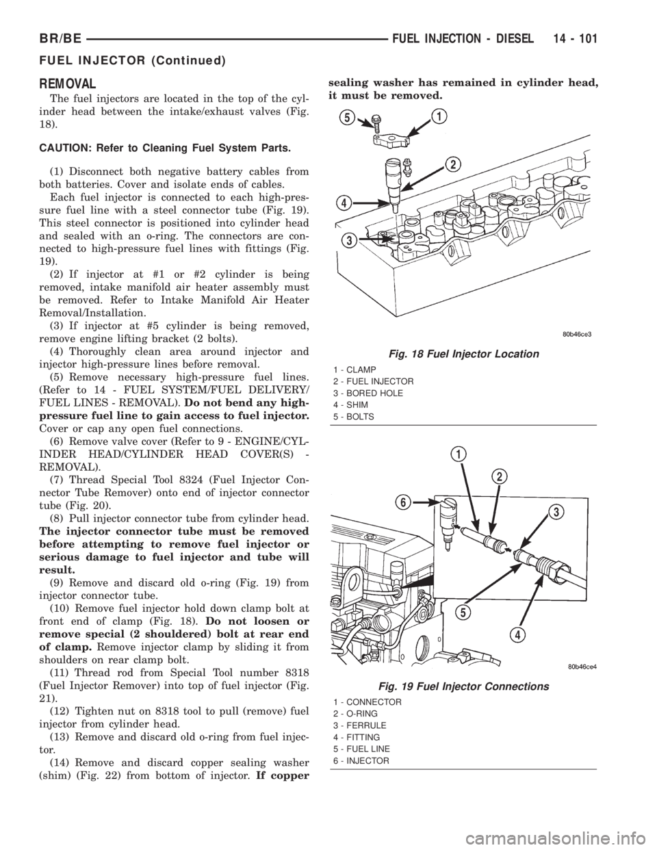
The fuel injectors are located in the top of the cyl-
inder head between the intake/exhaust valves (Fig.
18).
CAUTION: Refer to Cleaning Fuel System Parts.
(1) Disconnect both negative battery cables from
both batteries. Cover and isolate ends of cables.
Each fuel injector is connected to each high-pres-
sure fuel line with a steel connector tube (Fig. 19).
This steel connector is positioned into cylinder head
and sealed with an o-ring. The connectors are con-
nected to high-pressure fuel lines with fittings (Fig.
19).
(2) If injector at #1 or #2 cylinder is being
removed, intake manifold air heater assembly must
be removed. Refer to Intake Manifold Air Heater
Removal/Installation.
(3) If injector at #5 cylinder is being removed,
remove engine lifting bracket (2 bolts).
(4) Thoroughly clean area around injector and
injector high-pressure lines before removal.
(5) Remove necessary high-pressure fuel lines.
(Refer to 14 - FUEL SYSTEM/FUEL DELIVERY/
FUEL LINES - REMOVAL).Do not bend any high-
pressure fuel line to gain access to fuel injector.
Cover or cap any open fuel connections.
(6) Remove valve cover (Refer to 9 - ENGINE/CYL-
INDER HEAD/CYLINDER HEAD COVER(S) -
REMOVAL).
(7) Thread Special Tool 8324 (Fuel Injector Con-
nector Tube Remover) onto end of injector connector
tube (Fig. 20).
(8) Pull injector connector tube from cylinder head.
The injector connector tube must be removed
before attempting to remove fuel injector or
serious damage to fuel injector and tube will
result.
(9) Remove and discard old o-ring (Fig. 19) from
injector connector tube.
(10) Remove fuel injector hold down clamp bolt at
front end of clamp (Fig. 18).Do not loosen or
remove special (2 shouldered) bolt at rear end
of clamp.Remove injector clamp by sliding it from
shoulders on rear clamp bolt.
(11) Thread rod from Special Tool number 8318
(Fuel Injector Remover) into top of fuel injector (Fig.
21).
(12) Tighten nut on 8318 tool to pull (remove) fuel
injector from cylinder head.
(13) Remove and discard old o-ring from fuel injec-
tor.
(14) Remove and discard copper sealing washer
(shim) (Fig. 22) from bottom of injector.If coppersealing washer has remained in cylinder head,
it must be removed.
Fig. 18 Fuel Injector Location
1 - CLAMP
2 - FUEL INJECTOR
3 - BORED HOLE
4 - SHIM
5 - BOLTS
Fig. 19 Fuel Injector Connections
1 - CONNECTOR
2 - O-RING
3 - FERRULE
4 - FITTING
5 - FUEL LINE
6 - INJECTOR
BR/BEFUEL INJECTION - DIESEL 14 - 101
FUEL INJECTOR (Continued)
Page 1962 of 2255
DESCRIPTION - TIRE PRESSURE FOR HIGH
SPEEDS
Where speed limits allow the vehicle to be driven
at high speeds, correct tire inflation pressure is very
important. For speeds up to and including 120 km/h
(75 mph), tires must be inflated to the pressures
shown on the tire placard. For continuous speeds in
excess of 120 km/h (75 mph), tires must be inflated
to the maximum pressure specified on the tire side-
wall.
Vehicles loaded to the maximum capacity should
not be driven at continuous speeds above 75 mph
(120 km/h).
For emergency vehicles that are driven at speeds
over 90 mph (144 km/h), special high speed tires
must be used. Consult tire manufacturer for correct
inflation pressure recommendations.
DESCRIPTION - REPLACEMENT TIRES
The original equipment tires provide a proper bal-
ance of many characteristics such as:
²Ride
²Noise
²Handling
²Durability
²Tread life
²Traction
²Rolling resistance
²Speed capability
It is recommended that tires equivalent to the orig-
inal equipment tires be used when replacement is
needed.
Failure to use equivalent replacement tires may
adversely affect the safety and handling of the vehi-
cle.
The use of oversize tires may cause interference
with vehicle components. Under extremes of suspen-
sion and steering travel, interference with vehicle
components may cause tire damage.
WARNING: FAILURE TO EQUIP THE VEHICLE WITH
TIRES HAVING ADEQUATE SPEED CAPABILITY
CAN RESULT IN SUDDEN TIRE FAILURE.
DESCRIPTION - TIRE INFLATION PRESSURES
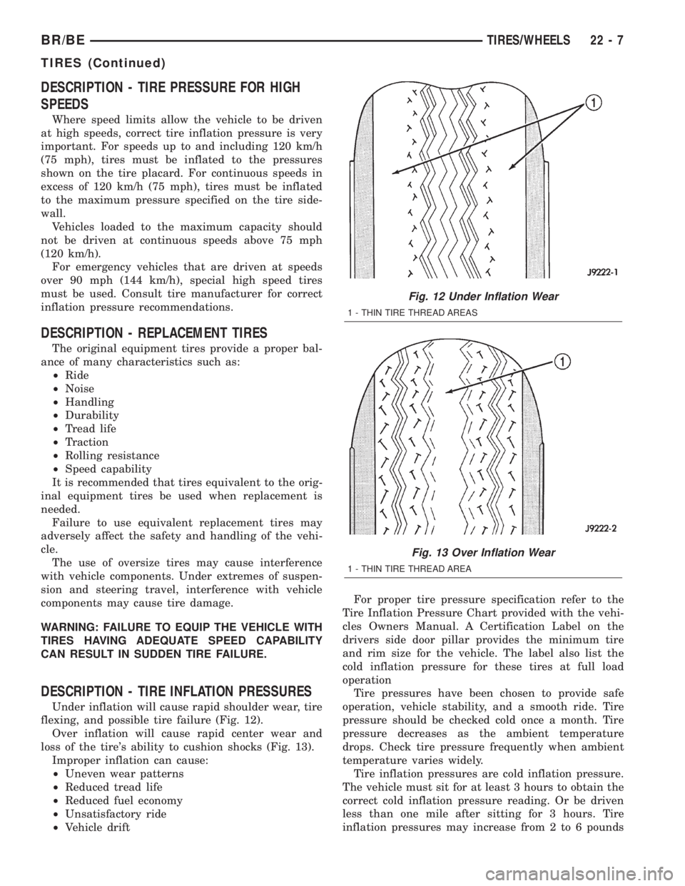
Under inflation will cause rapid shoulder wear, tire
flexing, and possible tire failure (Fig. 12).
Over inflation will cause rapid center wear and
loss of the tire's ability to cushion shocks (Fig. 13).
Improper inflation can cause:
²Uneven wear patterns
²Reduced tread life
²Reduced fuel economy
²Unsatisfactory ride
²Vehicle driftFor proper tire pressure specification refer to the
Tire Inflation Pressure Chart provided with the vehi-
cles Owners Manual. A Certification Label on the
drivers side door pillar provides the minimum tire
and rim size for the vehicle. The label also list the
cold inflation pressure for these tires at full load
operation
Tire pressures have been chosen to provide safe
operation, vehicle stability, and a smooth ride. Tire
pressure should be checked cold once a month. Tire
pressure decreases as the ambient temperature
drops. Check tire pressure frequently when ambient
temperature varies widely.
Tire inflation pressures are cold inflation pressure.
The vehicle must sit for at least 3 hours to obtain the
correct cold inflation pressure reading. Or be driven
less than one mile after sitting for 3 hours. Tire
inflation pressures may increase from 2 to 6 pounds
Fig. 12 Under Inflation Wear
1 - THIN TIRE THREAD AREAS
Fig. 13 Over Inflation Wear
1 - THIN TIRE THREAD AREA
BR/BETIRES/WHEELS 22 - 7
TIRES (Continued)
Page 2198 of 2255
The catalyst monitor uses dual oxygen sensors
(O2S's) to monitor the efficiency of the converter. The
dual O2S's sensor strategy is based on the fact that
as a catalyst deteriorates, its oxygen storage capacity
and its efficiency are both reduced. By monitoring
the oxygen storage capacity of a catalyst, its effi-
ciency can be indirectly calculated. The upstream
O2S is used to detect the amount of oxygen in the
exhaust gas before the gas enters the catalytic con-
verter. The PCM calculates the A/F mixture from the
output of the O2S. A low voltage indicates high oxy-
gen content (lean mixture). A high voltage indicates a
low content of oxygen (rich mixture).
When the upstream O2S detects a lean condition,
there is an abundance of oxygen in the exhaust gas.
A functioning converter would store this oxygen so it
can use it for the oxidation of HC and CO. As the
converter absorbs the oxygen, there will be a lack of
oxygen downstream of the converter. The output of
the downstream O2S will indicate limited activity in
this condition.
As the converter loses the ability to store oxygen,
the condition can be detected from the behavior of
the downstream O2S. When the efficiency drops, no
chemical reaction takes place. This means the con-
centration of oxygen will be the same downstream as
upstream. The output voltage of the downstream
O2S copies the voltage of the upstream sensor. The
only difference is a time lag (seen by the PCM)
between the switching of the O2S's.
To monitor the system, the number of lean-to-rich
switches of upstream and downstream O2S's is
counted. The ratio of downstream switches to
upstream switches is used to determine whether the
catalyst is operating properly. An effective catalyst
will have fewer downstream switches than it has
upstream switches i.e., a ratio closer to zero. For a
totally ineffective catalyst, this ratio will be one-to-
one, indicating that no oxidation occurs in the device.
The system must be monitored so that when cata-
lyst efficiency deteriorates and exhaust emissions
increase to over the legal limit, the MIL will be illu-
minated.
DESCRIPTION - TRIP DEFINITION
The term ªTripº has different meanings depending
on what the circumstances are. If the MIL (Malfunc-
tion Indicator Lamp) is OFF, a Trip is defined as
when the Oxygen Sensor Monitor and the Catalyst
Monitor have been completed in the same drive cycle.
When any Emission DTC is set, the MIL on the
dash is turned ON. When the MIL is ON, it takes 3
good trips to turn the MIL OFF. In this case, it
depends on what type of DTC is set to know what a
ªTripº is.For the Fuel Monitor or Mis-Fire Monitor (contin-
uous monitor), the vehicle must be operated in the
ªSimilar Condition Windowº for a specified amount of
time to be considered a Good Trip.
If a Non-Contiuous OBDII Monitor fails twice in a
row and turns ON the MIL, re-running that monitor
which previously failed, on the next start-up and
passing the monitor, is considered to be a Good Trip.
These will include the following:
²Oxygen Sensor
²Catalyst Monitor
²Purge Flow Monitor
²Leak Detection Pump Monitor (if equipped)
²EGR Monitor (if equipped)
²Oxygen Sensor Heater Monitor
If any other Emission DTC is set (not an OBDII
Monitor), a Good Trip is considered to be when the
Oxygen Sensor Monitor and Catalyst Monitor have
been completed; or 2 Minutes of engine run time if
the Oxygen Sensor Monitor or Catalyst Monitor have
been stopped from running.
It can take up to 2 Failures in a row to turn on the
MIL. After the MIL is ON, it takes 3 Good Trips to
turn the MIL OFF. After the MIL is OFF, the PCM
will self-erase the DTC after 40 Warm-up cycles. A
Warm-up cycle is counted when the ECT (Engine
Coolant Temperature Sensor) has crossed 160ÉF and
has risen by at least 40ÉF since the engine has been
started.
DESCRIPTION - COMPONENT MONITORS -
GAS ENGINES
There are several components that will affect vehi-
cle emissions if they malfunction. If one of these com-
ponents malfunctions the Malfunction Indicator
Lamp (MIL) will illuminate.
Some of the component monitors are checking for
proper operation of the part. Electrically operated
components now have input (rationality) and output
(functionality) checks. Previously, a component like
the Throttle Position sensor (TPS) was checked by
the PCM for an open or shorted circuit. If one of
these conditions occurred, a DTC was set. Now there
is a check to ensure that the component is working.
This is done by watching for a TPS indication of a
greater or lesser throttle opening than MAP and
engine rpm indicate. In the case of the TPS, if engine
vacuum is high and engine rpm is 1600 or greater,
and the TPS indicates a large throttle opening, a
DTC will be set. The same applies to low vacuum if
the TPS indicates a small throttle opening.
All open/short circuit checks, or any component
that has an associated limp-in, will set a fault after 1
trip with the malfunction present. Components with-
out an associated limp-in will take two trips to illu-
minate the MIL.
BR/BEEMISSIONS CONTROL 25 - 19
EMISSIONS CONTROL (Continued)
Page 2211 of 2255
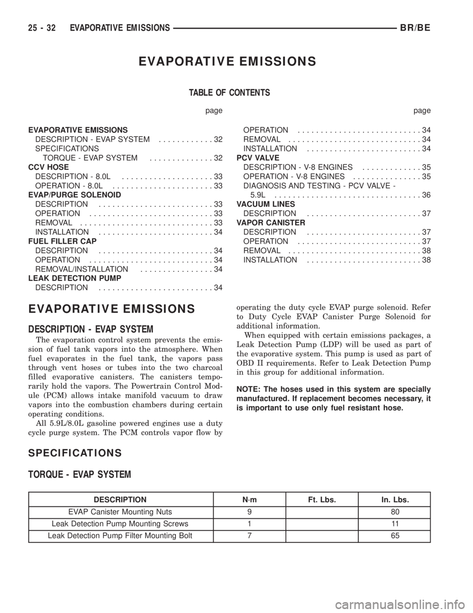
EVAPORATIVE EMISSIONS
TABLE OF CONTENTS
page page
EVAPORATIVE EMISSIONS
DESCRIPTION - EVAP SYSTEM............32
SPECIFICATIONS
TORQUE - EVAP SYSTEM..............32
CCV HOSE
DESCRIPTION - 8.0L....................33
OPERATION - 8.0L......................33
EVAP/PURGE SOLENOID
DESCRIPTION.........................33
OPERATION...........................33
REMOVAL.............................33
INSTALLATION.........................34
FUEL FILLER CAP
DESCRIPTION.........................34
OPERATION...........................34
REMOVAL/INSTALLATION................34
LEAK DETECTION PUMP
DESCRIPTION.........................34OPERATION...........................34
REMOVAL.............................34
INSTALLATION.........................34
P C V VA LV E
DESCRIPTION - V-8 ENGINES.............35
OPERATION - V-8 ENGINES...............35
DIAGNOSIS AND TESTING - PCV VALVE -
5.9L................................36
VACUUM LINES
DESCRIPTION.........................37
VAPOR CANISTER
DESCRIPTION.........................37
OPERATION...........................37
REMOVAL.............................38
INSTALLATION.........................38
EVAPORATIVE EMISSIONS
DESCRIPTION - EVAP SYSTEM
The evaporation control system prevents the emis-
sion of fuel tank vapors into the atmosphere. When
fuel evaporates in the fuel tank, the vapors pass
through vent hoses or tubes into the two charcoal
filled evaporative canisters. The canisters tempo-
rarily hold the vapors. The Powertrain Control Mod-
ule (PCM) allows intake manifold vacuum to draw
vapors into the combustion chambers during certain
operating conditions.
All 5.9L/8.0L gasoline powered engines use a duty
cycle purge system. The PCM controls vapor flow byoperating the duty cycle EVAP purge solenoid. Refer
to Duty Cycle EVAP Canister Purge Solenoid for
additional information.
When equipped with certain emissions packages, a
Leak Detection Pump (LDP) will be used as part of
the evaporative system. This pump is used as part of
OBD II requirements. Refer to Leak Detection Pump
in this group for additional information.
NOTE: The hoses used in this system are specially
manufactured. If replacement becomes necessary, it
is important to use only fuel resistant hose.
SPECIFICATIONS
TORQUE - EVAP SYSTEM
DESCRIPTION N´m Ft. Lbs. In. Lbs.
EVAP Canister Mounting Nuts 9 80
Leak Detection Pump Mounting Screws 1 11
Leak Detection Pump Filter Mounting Bolt 7 65
25 - 32 EVAPORATIVE EMISSIONSBR/BE
Page 2213 of 2255
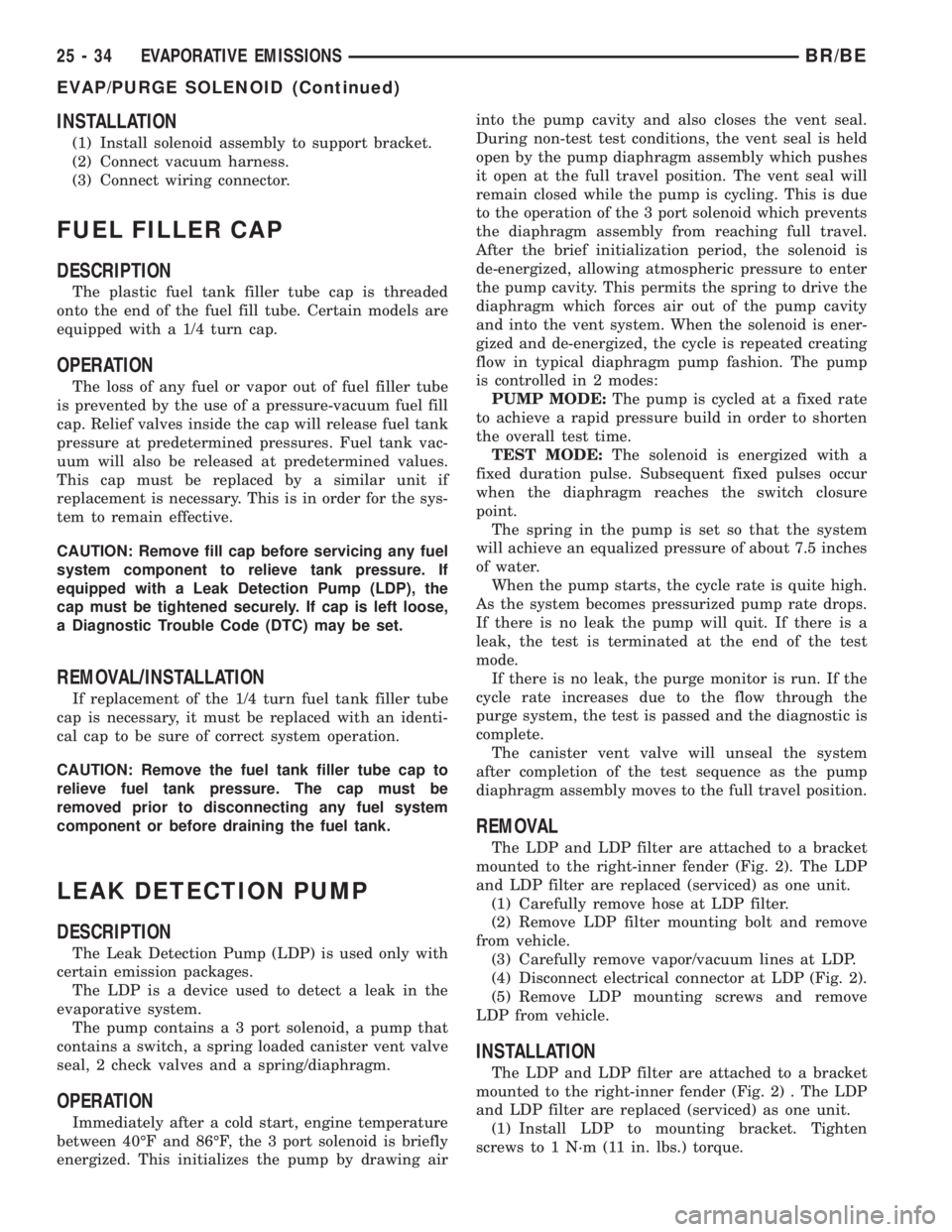
INSTALLATION
(1) Install solenoid assembly to support bracket.
(2) Connect vacuum harness.
(3) Connect wiring connector.
FUEL FILLER CAP
DESCRIPTION
The plastic fuel tank filler tube cap is threaded
onto the end of the fuel fill tube. Certain models are
equipped with a 1/4 turn cap.
OPERATION
The loss of any fuel or vapor out of fuel filler tube
is prevented by the use of a pressure-vacuum fuel fill
cap. Relief valves inside the cap will release fuel tank
pressure at predetermined pressures. Fuel tank vac-
uum will also be released at predetermined values.
This cap must be replaced by a similar unit if
replacement is necessary. This is in order for the sys-
tem to remain effective.
CAUTION: Remove fill cap before servicing any fuel
system component to relieve tank pressure. If
equipped with a Leak Detection Pump (LDP), the
cap must be tightened securely. If cap is left loose,
a Diagnostic Trouble Code (DTC) may be set.
REMOVAL/INSTALLATION
If replacement of the 1/4 turn fuel tank filler tube
cap is necessary, it must be replaced with an identi-
cal cap to be sure of correct system operation.
CAUTION: Remove the fuel tank filler tube cap to
relieve fuel tank pressure. The cap must be
removed prior to disconnecting any fuel system
component or before draining the fuel tank.
LEAK DETECTION PUMP
DESCRIPTION
The Leak Detection Pump (LDP) is used only with
certain emission packages.
The LDP is a device used to detect a leak in the
evaporative system.
The pump contains a 3 port solenoid, a pump that
contains a switch, a spring loaded canister vent valve
seal, 2 check valves and a spring/diaphragm.
OPERATION
Immediately after a cold start, engine temperature
between 40ÉF and 86ÉF, the 3 port solenoid is briefly
energized. This initializes the pump by drawing airinto the pump cavity and also closes the vent seal.
During non-test test conditions, the vent seal is held
open by the pump diaphragm assembly which pushes
it open at the full travel position. The vent seal will
remain closed while the pump is cycling. This is due
to the operation of the 3 port solenoid which prevents
the diaphragm assembly from reaching full travel.
After the brief initialization period, the solenoid is
de-energized, allowing atmospheric pressure to enter
the pump cavity. This permits the spring to drive the
diaphragm which forces air out of the pump cavity
and into the vent system. When the solenoid is ener-
gized and de-energized, the cycle is repeated creating
flow in typical diaphragm pump fashion. The pump
is controlled in 2 modes:
PUMP MODE:The pump is cycled at a fixed rate
to achieve a rapid pressure build in order to shorten
the overall test time.
TEST MODE:The solenoid is energized with a
fixed duration pulse. Subsequent fixed pulses occur
when the diaphragm reaches the switch closure
point.
The spring in the pump is set so that the system
will achieve an equalized pressure of about 7.5 inches
of water.
When the pump starts, the cycle rate is quite high.
As the system becomes pressurized pump rate drops.
If there is no leak the pump will quit. If there is a
leak, the test is terminated at the end of the test
mode.
If there is no leak, the purge monitor is run. If the
cycle rate increases due to the flow through the
purge system, the test is passed and the diagnostic is
complete.
The canister vent valve will unseal the system
after completion of the test sequence as the pump
diaphragm assembly moves to the full travel position.
REMOVAL
The LDP and LDP filter are attached to a bracket
mounted to the right-inner fender (Fig. 2). The LDP
and LDP filter are replaced (serviced) as one unit.
(1) Carefully remove hose at LDP filter.
(2) Remove LDP filter mounting bolt and remove
from vehicle.
(3) Carefully remove vapor/vacuum lines at LDP.
(4) Disconnect electrical connector at LDP (Fig. 2).
(5) Remove LDP mounting screws and remove
LDP from vehicle.
INSTALLATION
The LDP and LDP filter are attached to a bracket
mounted to the right-inner fender (Fig. 2) . The LDP
and LDP filter are replaced (serviced) as one unit.
(1) Install LDP to mounting bracket. Tighten
screws to 1 N´m (11 in. lbs.) torque.
25 - 34 EVAPORATIVE EMISSIONSBR/BE
EVAP/PURGE SOLENOID (Continued)