washer fluid DODGE RAM 2002 Service Workshop Manual
[x] Cancel search | Manufacturer: DODGE, Model Year: 2002, Model line: RAM, Model: DODGE RAM 2002Pages: 2255, PDF Size: 62.07 MB
Page 1658 of 2255
Inspect the piston and retainer seal surfaces for
nicks or scratches. Minor scratches can be removed
with crocus cloth. However, replace the piston and/or
retainer if the seal surfaces are seriously scored.
Check condition of the fiber thrust washer and
metal output shaft thrust washer. Replace either
washer if worn or damaged.
Check condition of the seal rings on the input shaft
and clutch retainer hub. Replace the seal rings only
if worn, distorted, or damaged. The input shaft front
seal ring is teflon with chamfered ends. The rear ring
is metal with interlocking ends.
Check the input shaft for wear, or damage. Replace
the shaft if worn, scored or damaged in any way.
ASSEMBLY
(1) Soak clutch discs in transmission fluid while
assembling other clutch parts.
(2) Install new seal rings on clutch retainer hub
and input shaft if necessary.
(a) Be sure clutch hub seal ring is fully seated in
groove and is not twisted.(3) Lubricate splined end of input shaft and clutch
retainer with transmission fluid. Then partially press
input shaft into retainer (Fig. 224). Use a suitably
sized press tool to support retainer as close to input
shaft as possible.
(4) Install input shaft retaining ring.
(5) Press the input shaft the remainder of the way
into the clutch retainer.
(6) Install new seals on clutch piston. Be sure lip
of each seal faces interior of clutch retainer.
(7)
Lubricate lip of piston seals with generous quan-
tity of MopartDoor Ease. Then lubricate retainer hub
and bore with light coat of transmission fluid.
(8) Install clutch piston in retainer. Use twisting
motion to seat piston in bottom of retainer. A thin
strip of plastic (about 0.0209thick), can be used to
guide seals into place if necessary.
CAUTION: Never push the clutch piston straight in.
This will fold the seals over causing leakage and
clutch slip. In addition, never use any type of metal
tool to help ease the piston seals into place. Metal
tools will cut, shave, or score the seals.
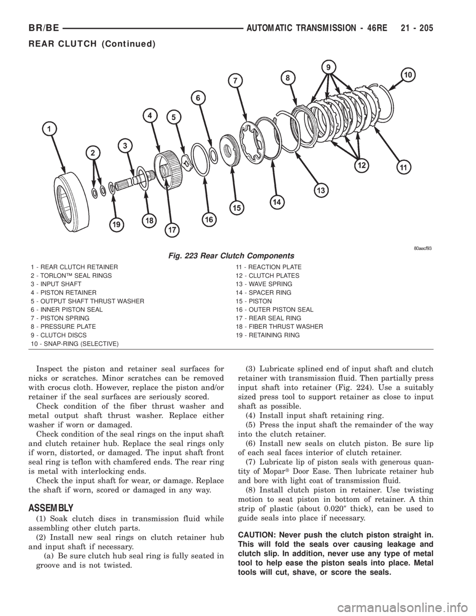
Fig. 223 Rear Clutch Components
1 - REAR CLUTCH RETAINER 11 - REACTION PLATE
2 - TORLONŸ SEAL RINGS 12 - CLUTCH PLATES
3 - INPUT SHAFT 13 - WAVE SPRING
4 - PISTON RETAINER 14 - SPACER RING
5 - OUTPUT SHAFT THRUST WASHER 15 - PISTON
6 - INNER PISTON SEAL 16 - OUTER PISTON SEAL
7 - PISTON SPRING 17 - REAR SEAL RING
8 - PRESSURE PLATE 18 - FIBER THRUST WASHER
9 - CLUTCH DISCS 19 - RETAINING RING
10 - SNAP-RING (SELECTIVE)
BR/BEAUTOMATIC TRANSMISSION - 46RE 21 - 205
REAR CLUTCH (Continued)
Page 1668 of 2255
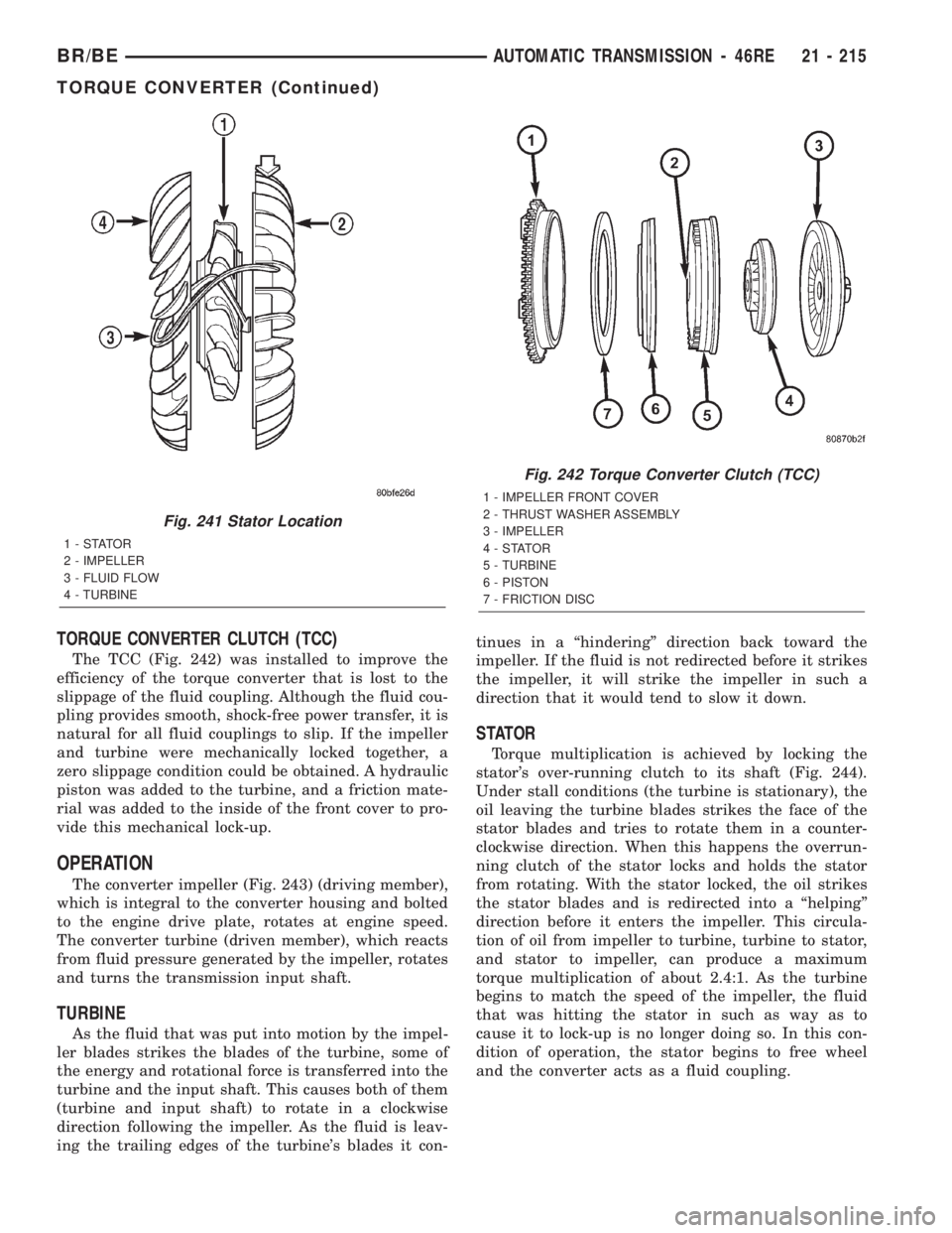
TORQUE CONVERTER CLUTCH (TCC)
The TCC (Fig. 242) was installed to improve the
efficiency of the torque converter that is lost to the
slippage of the fluid coupling. Although the fluid cou-
pling provides smooth, shock-free power transfer, it is
natural for all fluid couplings to slip. If the impeller
and turbine were mechanically locked together, a
zero slippage condition could be obtained. A hydraulic
piston was added to the turbine, and a friction mate-
rial was added to the inside of the front cover to pro-
vide this mechanical lock-up.
OPERATION
The converter impeller (Fig. 243) (driving member),
which is integral to the converter housing and bolted
to the engine drive plate, rotates at engine speed.
The converter turbine (driven member), which reacts
from fluid pressure generated by the impeller, rotates
and turns the transmission input shaft.
TURBINE
As the fluid that was put into motion by the impel-
ler blades strikes the blades of the turbine, some of
the energy and rotational force is transferred into the
turbine and the input shaft. This causes both of them
(turbine and input shaft) to rotate in a clockwise
direction following the impeller. As the fluid is leav-
ing the trailing edges of the turbine's blades it con-tinues in a ªhinderingº direction back toward the
impeller. If the fluid is not redirected before it strikes
the impeller, it will strike the impeller in such a
direction that it would tend to slow it down.
STATOR
Torque multiplication is achieved by locking the
stator's over-running clutch to its shaft (Fig. 244).
Under stall conditions (the turbine is stationary), the
oil leaving the turbine blades strikes the face of the
stator blades and tries to rotate them in a counter-
clockwise direction. When this happens the overrun-
ning clutch of the stator locks and holds the stator
from rotating. With the stator locked, the oil strikes
the stator blades and is redirected into a ªhelpingº
direction before it enters the impeller. This circula-
tion of oil from impeller to turbine, turbine to stator,
and stator to impeller, can produce a maximum
torque multiplication of about 2.4:1. As the turbine
begins to match the speed of the impeller, the fluid
that was hitting the stator in such as way as to
cause it to lock-up is no longer doing so. In this con-
dition of operation, the stator begins to free wheel
and the converter acts as a fluid coupling.
Fig. 241 Stator Location
1-STATOR
2 - IMPELLER
3 - FLUID FLOW
4 - TURBINE
Fig. 242 Torque Converter Clutch (TCC)
1 - IMPELLER FRONT COVER
2 - THRUST WASHER ASSEMBLY
3 - IMPELLER
4-STATOR
5 - TURBINE
6 - PISTON
7 - FRICTION DISC
BR/BEAUTOMATIC TRANSMISSION - 46RE 21 - 215
TORQUE CONVERTER (Continued)
Page 1689 of 2255
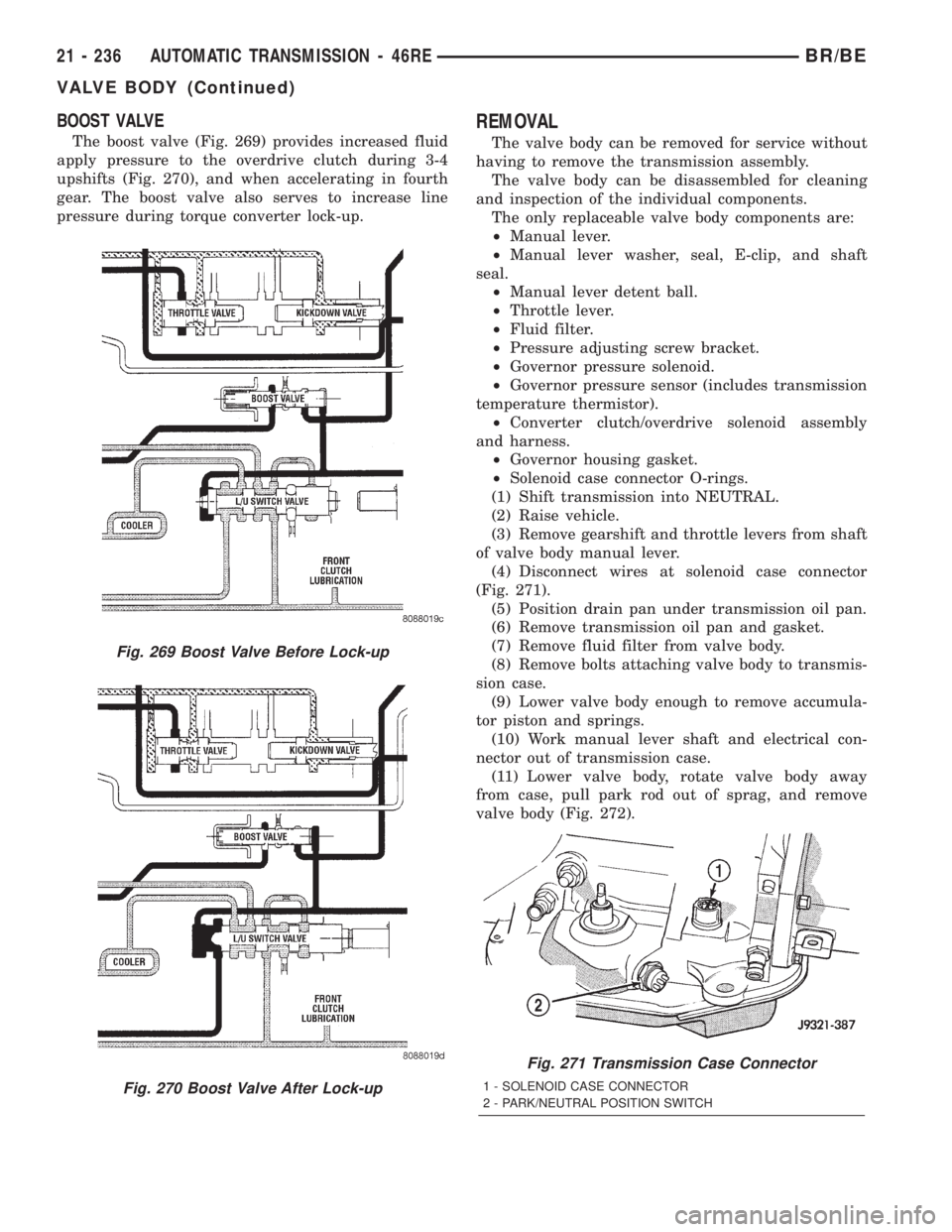
BOOST VALVE
The boost valve (Fig. 269) provides increased fluid
apply pressure to the overdrive clutch during 3-4
upshifts (Fig. 270), and when accelerating in fourth
gear. The boost valve also serves to increase line
pressure during torque converter lock-up.
REMOVAL
The valve body can be removed for service without
having to remove the transmission assembly.
The valve body can be disassembled for cleaning
and inspection of the individual components.
The only replaceable valve body components are:
²Manual lever.
²Manual lever washer, seal, E-clip, and shaft
seal.
²Manual lever detent ball.
²Throttle lever.
²Fluid filter.
²Pressure adjusting screw bracket.
²Governor pressure solenoid.
²Governor pressure sensor (includes transmission
temperature thermistor).
²Converter clutch/overdrive solenoid assembly
and harness.
²Governor housing gasket.
²Solenoid case connector O-rings.
(1) Shift transmission into NEUTRAL.
(2) Raise vehicle.
(3) Remove gearshift and throttle levers from shaft
of valve body manual lever.
(4) Disconnect wires at solenoid case connector
(Fig. 271).
(5) Position drain pan under transmission oil pan.
(6) Remove transmission oil pan and gasket.
(7) Remove fluid filter from valve body.
(8) Remove bolts attaching valve body to transmis-
sion case.
(9) Lower valve body enough to remove accumula-
tor piston and springs.
(10) Work manual lever shaft and electrical con-
nector out of transmission case.
(11) Lower valve body, rotate valve body away
from case, pull park rod out of sprag, and remove
valve body (Fig. 272).
Fig. 269 Boost Valve Before Lock-up
Fig. 270 Boost Valve After Lock-up
Fig. 271 Transmission Case Connector
1 - SOLENOID CASE CONNECTOR
2 - PARK/NEUTRAL POSITION SWITCH
21 - 236 AUTOMATIC TRANSMISSION - 46REBR/BE
VALVE BODY (Continued)
Page 1699 of 2255
Check the two separator plates for distortion or
damage of any kind. Inspect the upper housing,
lower housing, 3-4 accumulator housing, and transfer
plate carefully. Be sure all fluid passages are clean
and clear. Check condition of the upper housing and
transfer plate check balls as well. The check balls
and ball seats must not be worn or damaged.
Trial fit each valve and plug in its bore to check
freedom of operation. When clean and dry, the valves
and plugs should drop freely into the bores.
Valve body bores do not change dimensionally with
use. If the valve body functioned correctly when new,
it will continue to operate properly after cleaning and
inspection. It should not be necessary to replace a
valve body assembly unless it is damaged in han-
dling.
The only serviceable valve body components are
listed below. The remaining valve body components
are serviced only as part of a complete valve body
assembly. Serviceable parts are:²dual solenoid and harness assembly
²solenoid gasket
²solenoid case connector O-rings and shoulder
bolt
²switch valve and spring
²pressure adjusting screw and bracket assembly
²throttle lever
²manual lever and shaft seal
²throttle lever shaft seal, washer, and E-clip
²fluid filter and screws
²detent ball and spring
²valve body screws
²governor pressure solenoid
²governor pressure sensor and retaining clip
²park lock rod and E-clip
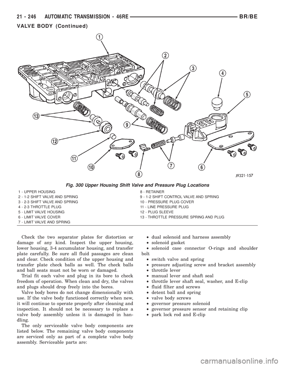
Fig. 300 Upper Housing Shift Valve and Pressure Plug Locations
1 - UPPER HOUSING 8 - RETAINER
2 - 1-2 SHIFT VALVE AND SPRING 9 - 1-2 SHIFT CONTROL VALVE AND SPRING
3 - 2-3 SHIFT VALVE AND SPRING 10 - PRESSURE PLUG COVER
4 - 2-3 THROTTLE PLUG 11 - LINE PRESSURE PLUG
5 - LIMIT VALVE HOUSING 12 - PLUG SLEEVE
6 - LIMIT VALVE COVER 13 - THROTTLE PRESSURE SPRING AND PLUG
7 - LIMIT VALVE AND SPRING
21 - 246 AUTOMATIC TRANSMISSION - 46REBR/BE
VALVE BODY (Continued)
Page 1746 of 2255
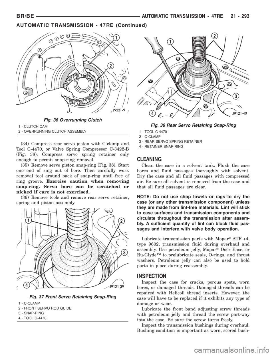
(34) Compress rear servo piston with C-clamp and
Tool C-4470, or Valve Spring Compressor C-3422-B
(Fig. 38). Compress servo spring retainer only
enough to permit snap-ring removal.
(35) Remove servo piston snap-ring (Fig. 38). Start
one end of ring out of bore. Then carefully work
removal tool around back of snap-ring until free of
ring groove.Exercise caution when removing
snap-ring. Servo bore can be scratched or
nicked if care is not exercised.
(36) Remove tools and remove rear servo retainer,
spring and piston assembly.
CLEANING
Clean the case in a solvent tank. Flush the case
bores and fluid passages thoroughly with solvent.
Dry the case and all fluid passages with compressed
air. Be sure all solvent is removed from the case and
that all fluid passages are clear.
NOTE: Do not use shop towels or rags to dry the
case (or any other transmission component) unless
they are made from lint-free materials. Lint will stick
to case surfaces and transmission components and
circulate throughout the transmission after assem-
bly. A sufficient quantity of lint can block fluid pas-
sages and interfere with valve body operation.
Lubricate transmission parts with MopartATF +4,
type 9602, transmission fluid during overhaul and
assembly. Use petroleum jelly, MopartDoor Ease, or
Ru-GlydeŸ to prelubricate seals, O-rings, and thrust
washers. Petroleum jelly can also be used to hold
parts in place during reassembly.
INSPECTION
Inspect the case for cracks, porous spots, worn
bores, or damaged threads. Damaged threads can be
repaired with Helicoil thread inserts. However, the
case will have to be replaced if it exhibits any type of
damage or wear.
Lubricate the front band adjusting screw threads
with petroleum jelly and thread the screw part-way
into the case. Be sure the screw turns freely.
Inspect the transmission bushings during overhaul.
Bushing condition is important as worn, scored bush-
Fig. 36 Overrunning Clutch
1 - CLUTCH CAM
2 - OVERRUNNING CLUTCH ASSEMBLY
Fig. 37 Front Servo Retaining Snap-Ring
1 - C-CLAMP
2 - FRONT SERVO ROD GUIDE
3 - SNAP-RING
4 - TOOL C-4470
Fig. 38 Rear Servo Retaining Snap-Ring
1 - TOOL C-4470
2 - C-CLAMP
3 - REAR SERVO SPRING RETAINER
4 - RETAINER SNAP-RING
BR/BEAUTOMATIC TRANSMISSION - 47RE 21 - 293
AUTOMATIC TRANSMISSION - 47RE (Continued)
Page 1747 of 2255
ings contribute to low pressures, clutch slip and
accelerated wear of other components. However, do
not replace bushings as a matter of course. Replace
bushings only when they are actually worn, or
scored.
Use recommended tools to replace bushings. The
tools are sized and designed to remove, install, and
seat bushings correctly. The bushing replacement
tools are included in Bushing Tool Set C-3887-B.
Pre-sized service bushings are available for
replacement purposes. Only the sun gear bushings
are not serviced.
The use of crocus cloth is permissible where neces-
sary, providing it is used carefully. When used on
shafts, or valves, use extreme care to avoid rounding
off sharp edges. Sharp edges are vital as they pre-
vent foreign matter from getting between the valve
and valve bore.
Do not reuse oil seals, gaskets, seal rings, or
O-rings during overhaul. Replace these parts as a
matter of course. Also do not reuse snap rings or
E-clips that are bent or distorted. Replace these parts
as well.
ASSEMBLY
Do not allow dirt, grease, or foreign material to
enter the case or transmission components during
assembly. Keep the transmission case and compo-
nents clean. Also make sure the tools and workbench
area used for reassembly operations are equally
clean.
Shop towels used for wiping off tools and your
hands must be made fromlint freematerials. Lint
will stick to transmission parts and could interfere
with valve operation or even restrict fluid passages.
Lubricate transmission clutch and gear compo-
nents with MopartATF +4, type 9602, during reas-
sembly. Soak clutch discs in transmission fluid before
installation.
Use MopartDoor Ease, or Ru-GlydeŸ on piston
seals and o-rings to ease installation. Petroleum jelly
can also be used to lubricate and hold thrust washers
and plates in position during assembly.
Do not use chassis grease, bearing grease,
white grease, or similar lubricants on any part.
These types of lubricants can eventually block or
restrict fluid passages and valve operation. Use
petroleum jelly only.
Do not force parts into place. The transmission
components and sub-assemblies are easily installed
by hand when properly aligned. If a part seems dif-
ficult to install, it is either misaligned or incorrectly
assembled. Verify that thrust washers, thrust plates
and seal rings are correctly positioned.
The planetary geartrain, front/rear clutch assem-
blies and oil pump are all much easier to installwhen the transmission case is upright. Either tilt the
case upward with wood blocks, or cut a hole in the
bench large enough for the intermediate shaft and
rear support. Then lower the shaft and support into
the hole and support the rear of the case directly on
the bench.
FRONT/REAR SERVO
(1) Lubricate rear servo piston seal with Mopart
Door Ease or ATF +4. Lubricate servo bore in case
with ATF +4.
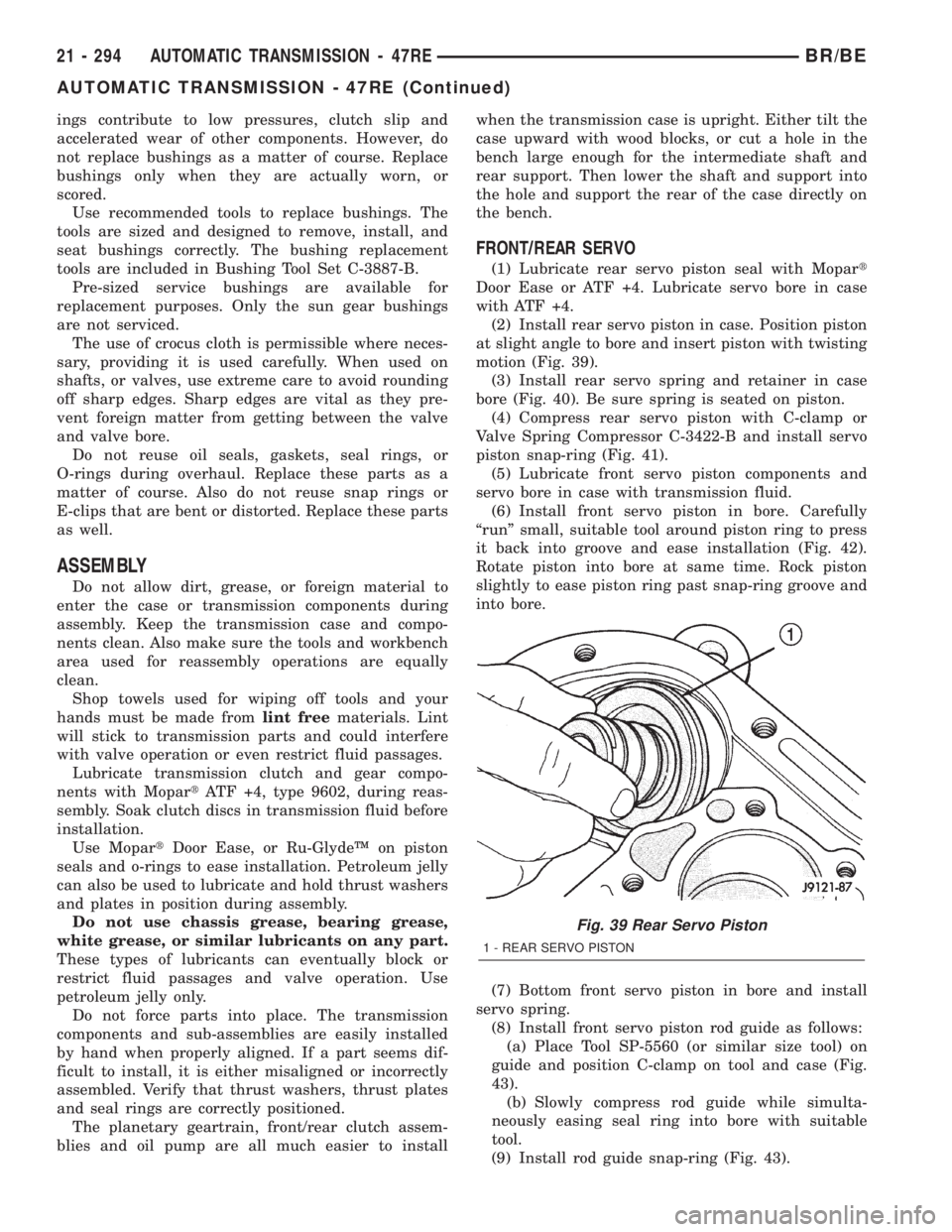
(2) Install rear servo piston in case. Position piston
at slight angle to bore and insert piston with twisting
motion (Fig. 39).
(3) Install rear servo spring and retainer in case
bore (Fig. 40). Be sure spring is seated on piston.
(4) Compress rear servo piston with C-clamp or
Valve Spring Compressor C-3422-B and install servo
piston snap-ring (Fig. 41).
(5) Lubricate front servo piston components and
servo bore in case with transmission fluid.
(6) Install front servo piston in bore. Carefully
ªrunº small, suitable tool around piston ring to press
it back into groove and ease installation (Fig. 42).
Rotate piston into bore at same time. Rock piston
slightly to ease piston ring past snap-ring groove and
into bore.
(7) Bottom front servo piston in bore and install
servo spring.
(8) Install front servo piston rod guide as follows:
(a) Place Tool SP-5560 (or similar size tool) on
guide and position C-clamp on tool and case (Fig.
43).
(b) Slowly compress rod guide while simulta-
neously easing seal ring into bore with suitable
tool.
(9) Install rod guide snap-ring (Fig. 43).
Fig. 39 Rear Servo Piston
1 - REAR SERVO PISTON
21 - 294 AUTOMATIC TRANSMISSION - 47REBR/BE
AUTOMATIC TRANSMISSION - 47RE (Continued)
Page 1750 of 2255
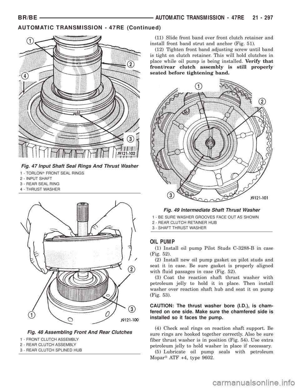
(11) Slide front band over front clutch retainer and
install front band strut and anchor (Fig. 51).
(12) Tighten front band adjusting screw until band
is tight on clutch retainer. This will hold clutches in
place while oil pump is being installed.Verify that
front/rear clutch assembly is still properly
seated before tightening band.
OIL PUMP
(1) Install oil pump Pilot Studs C-3288-B in case
(Fig. 52).
(2) Install new oil pump gasket on pilot studs and
seat it in case. Be sure gasket is properly aligned
with fluid passages in case (Fig. 52).
(3) Coat the reaction shaft thrust washer with
petroleum jelly to hold it in place. Then install
washer over reaction shaft hub and seat it on pump
(Fig. 53).
CAUTION: The thrust washer bore (I.D.), is cham-
fered on one side. Make sure the chamfered side is
installed so it faces the pump.
(4) Check seal rings on reaction shaft support. Be
sure rings are hooked together correctly. Also be sure
fiber thrust washer is in position (Fig. 54). Use extra
petroleum jelly to hold washer in place if necessary.
(5) Lubricate oil pump seals with petroleum
MopartATF +4, type 9602.
Fig. 47 Input Shaft Seal Rings And Thrust Washer
1 - TORLONTFRONT SEAL RINGS
2 - INPUT SHAFT
3 - REAR SEAL RING
4 - THRUST WASHER
Fig. 48 Assembling Front And Rear Clutches
1 - FRONT CLUTCH ASSEMBLY
2 - REAR CLUTCH ASSEMBLY
3 - REAR CLUTCH SPLINED HUB
Fig. 49 Intermediate Shaft Thrust Washer
1 - BE SURE WASHER GROOVES FACE OUT AS SHOWN
2 - REAR CLUTCH RETAINER HUB
3 - SHAFT THRUST WASHER
BR/BEAUTOMATIC TRANSMISSION - 47RE 21 - 297
AUTOMATIC TRANSMISSION - 47RE (Continued)
Page 1767 of 2255
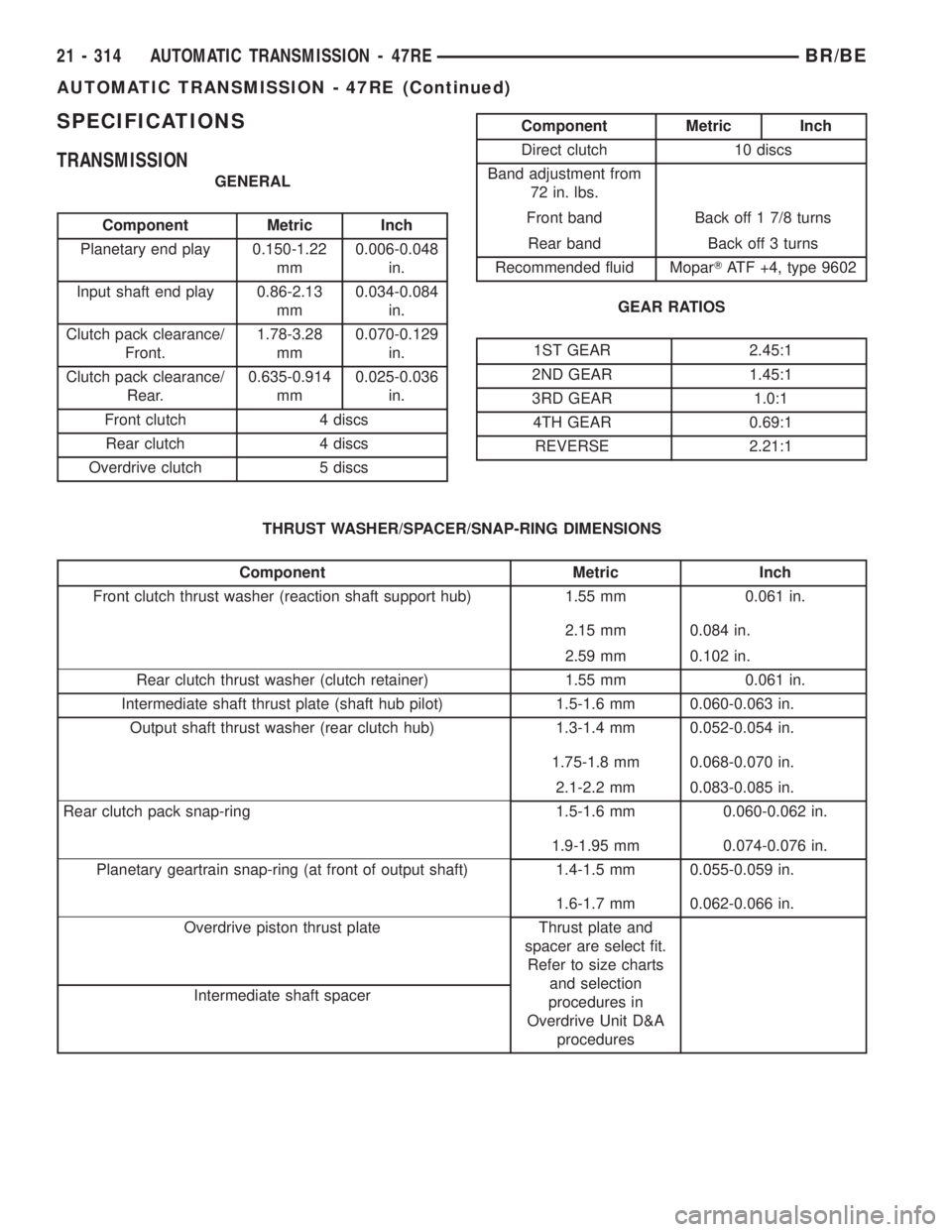
SPECIFICATIONS
TRANSMISSION
GENERAL
Component Metric Inch
Planetary end play 0.150-1.22
mm0.006-0.048
in.
Input shaft end play 0.86-2.13
mm0.034-0.084
in.
Clutch pack clearance/
Front.1.78-3.28
mm0.070-0.129
in.
Clutch pack clearance/
Rear.0.635-0.914
mm0.025-0.036
in.
Front clutch 4 discs
Rear clutch 4 discs
Overdrive clutch 5 discs
Component Metric Inch
Direct clutch 10 discs
Band adjustment from
72 in. lbs.
Front band Back off 1 7/8 turns
Rear band Back off 3 turns
Recommended fluid MoparTATF +4, type 9602
GEAR RATIOS
1ST GEAR 2.45:1
2ND GEAR 1.45:1
3RD GEAR 1.0:1
4TH GEAR 0.69:1
REVERSE 2.21:1
THRUST WASHER/SPACER/SNAP-RING DIMENSIONS
Component Metric Inch
Front clutch thrust washer (reaction shaft support hub) 1.55 mm 0.061 in.
2.15 mm 0.084 in.
2.59 mm 0.102 in.
Rear clutch thrust washer (clutch retainer) 1.55 mm 0.061 in.
Intermediate shaft thrust plate (shaft hub pilot) 1.5-1.6 mm 0.060-0.063 in.
Output shaft thrust washer (rear clutch hub) 1.3-1.4 mm 0.052-0.054 in.
1.75-1.8 mm 0.068-0.070 in.
2.1-2.2 mm 0.083-0.085 in.
Rear clutch pack snap-ring 1.5-1.6 mm 0.060-0.062 in.
1.9-1.95 mm 0.074-0.076 in.
Planetary geartrain snap-ring (at front of output shaft) 1.4-1.5 mm 0.055-0.059 in.
1.6-1.7 mm 0.062-0.066 in.
Overdrive piston thrust plate Thrust plate and
spacer are select fit.
Refer to size charts
and selection
procedures in
Overdrive Unit D&A
procedures Intermediate shaft spacer
21 - 314 AUTOMATIC TRANSMISSION - 47REBR/BE
AUTOMATIC TRANSMISSION - 47RE (Continued)
Page 1789 of 2255
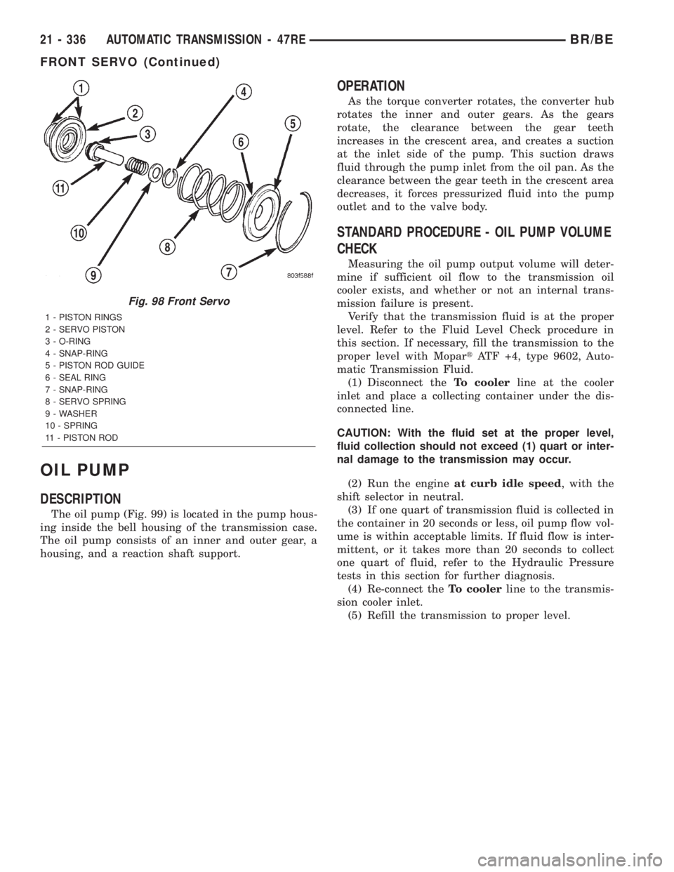
OIL PUMP
DESCRIPTION
The oil pump (Fig. 99) is located in the pump hous-
ing inside the bell housing of the transmission case.
The oil pump consists of an inner and outer gear, a
housing, and a reaction shaft support.
OPERATION
As the torque converter rotates, the converter hub
rotates the inner and outer gears. As the gears
rotate, the clearance between the gear teeth
increases in the crescent area, and creates a suction
at the inlet side of the pump. This suction draws
fluid through the pump inlet from the oil pan. As the
clearance between the gear teeth in the crescent area
decreases, it forces pressurized fluid into the pump
outlet and to the valve body.
STANDARD PROCEDURE - OIL PUMP VOLUME
CHECK
Measuring the oil pump output volume will deter-
mine if sufficient oil flow to the transmission oil
cooler exists, and whether or not an internal trans-
mission failure is present.
Verify that the transmission fluid is at the proper
level. Refer to the Fluid Level Check procedure in
this section. If necessary, fill the transmission to the
proper level with MopartATF +4, type 9602, Auto-
matic Transmission Fluid.
(1) Disconnect theTo coolerline at the cooler
inlet and place a collecting container under the dis-
connected line.
CAUTION: With the fluid set at the proper level,
fluid collection should not exceed (1) quart or inter-
nal damage to the transmission may occur.
(2) Run the engineat curb idle speed, with the
shift selector in neutral.
(3) If one quart of transmission fluid is collected in
the container in 20 seconds or less, oil pump flow vol-
ume is within acceptable limits. If fluid flow is inter-
mittent, or it takes more than 20 seconds to collect
one quart of fluid, refer to the Hydraulic Pressure
tests in this section for further diagnosis.
(4) Re-connect theTo coolerline to the transmis-
sion cooler inlet.
(5) Refill the transmission to proper level.
Fig. 98 Front Servo
1 - PISTON RINGS
2 - SERVO PISTON
3 - O-RING
4 - SNAP-RING
5 - PISTON ROD GUIDE
6 - SEAL RING
7 - SNAP-RING
8 - SERVO SPRING
9 - WASHER
10 - SPRING
11 - PISTON ROD
21 - 336 AUTOMATIC TRANSMISSION - 47REBR/BE
FRONT SERVO (Continued)
Page 1794 of 2255
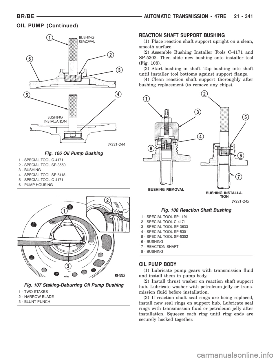
REACTION SHAFT SUPPORT BUSHING
(1) Place reaction shaft support upright on a clean,
smooth surface.
(2) Assemble Bushing Installer Tools C-4171 and
SP-5302. Then slide new bushing onto installer tool
(Fig. 108).
(3) Start bushing in shaft. Tap bushing into shaft
until installer tool bottoms against support flange.
(4) Clean reaction shaft support thoroughly after
bushing replacement (to remove any chips).
OIL PUMP BODY
(1) Lubricate pump gears with transmission fluid
and install them in pump body.
(2) Install thrust washer on reaction shaft support
hub. Lubricate washer with petroleum jelly or trans-
mission fluid before installation.
(3) If reaction shaft seal rings are being replaced,
install new seal rings on support hub. Lubricate seal
rings with transmission fluid or petroleum jelly after
installation. Squeeze each ring until ring ends are
securely hooked together.
Fig. 106 Oil Pump Bushing
1 - SPECIAL TOOL C-4171
2 - SPECIAL TOOL SP-3550
3 - BUSHING
4 - SPECIAL TOOL SP-5118
5 - SPECIAL TOOL C-4171
6 - PUMP HOUSING
Fig. 107 Staking-Deburring Oil Pump Bushing
1 - TWO STAKES
2 - NARROW BLADE
3 - BLUNT PUNCH
Fig. 108 Reaction Shaft Bushing
1 - SPECIAL TOOL SP-1191
2 - SPECIAL TOOL C-4171
3 - SPECIAL TOOL SP-3633
4 - SPECIAL TOOL SP-5301
5 - SPECIAL TOOL SP-5302
6 - BUSHING
7 - REACTION SHAFT
8 - BUSHING
BR/BEAUTOMATIC TRANSMISSION - 47RE 21 - 341
OIL PUMP (Continued)