Crankshaft DODGE RAM 2002 Service Repair Manual
[x] Cancel search | Manufacturer: DODGE, Model Year: 2002, Model line: RAM, Model: DODGE RAM 2002Pages: 2255, PDF Size: 62.07 MB
Page 232 of 2255
CLUTCH
TABLE OF CONTENTS
page page
CLUTCH
DESCRIPTION..........................1
OPERATION............................2
WARNING.............................2
DIAGNOSIS AND TESTING - CLUTCH........2
SPECIFICATIONS - CLUTCH...............7
CLUTCH DISC
REMOVAL.............................7
INSTALLATION..........................8
CLUTCH HOUSING
DIAGNOSIS AND TESTING - CLUTCH
HOUSING............................9
REMOVAL.............................11
INSTALLATION.........................11
CLUTCH RELEASE BEARING
REMOVAL.............................12
INSTALLATION.........................12FLYWHEEL
DIAGNOSIS AND TESTING - FLYWHEEL.....13
DISASSEMBLY.........................13
ASSEMBLY............................14
PILOT BEARING
REMOVAL.............................14
INSTALLATION.........................14
CLUTCH PEDAL
REMOVAL.............................15
INSTALLATION.........................15
LINKAGE
REMOVAL.............................15
INSTALLATION.........................16
CLUTCH PEDAL POSITION SWITCH
DESCRIPTION.........................17
OPERATION...........................17
CLUTCH
DESCRIPTION
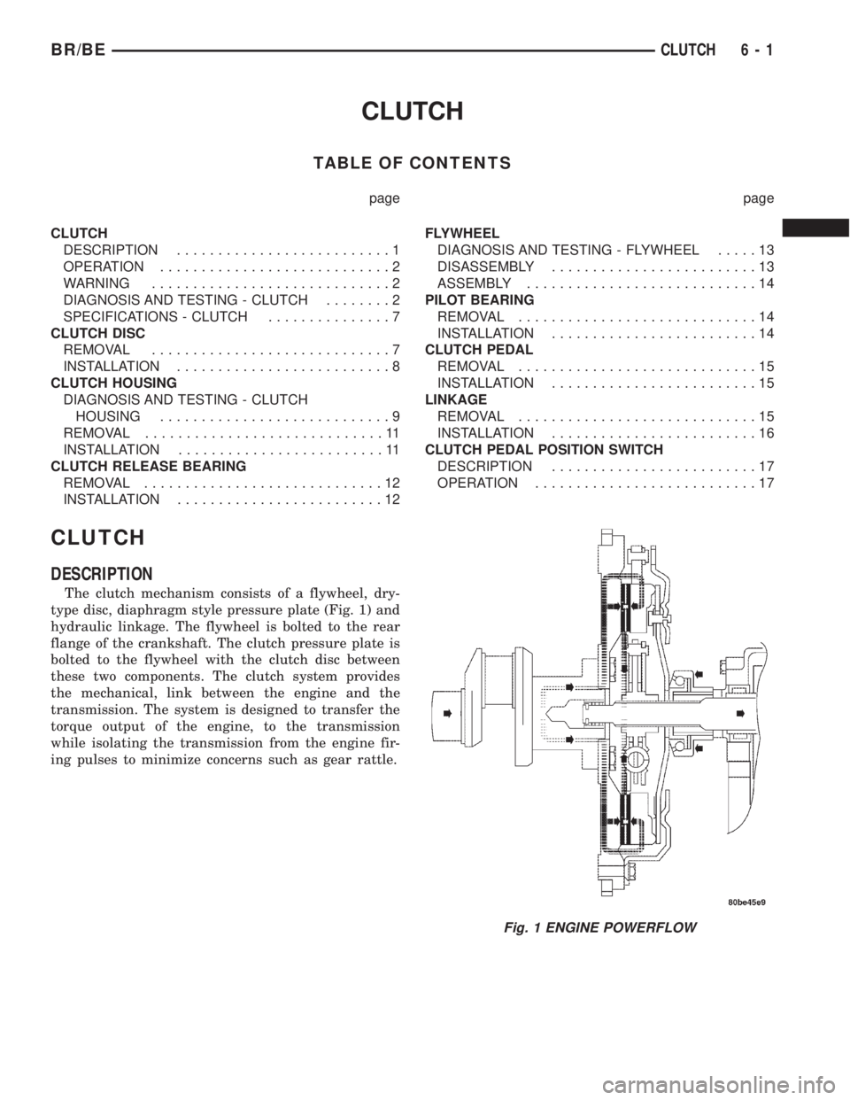
The clutch mechanism consists of a flywheel, dry-
type disc, diaphragm style pressure plate (Fig. 1) and
hydraulic linkage. The flywheel is bolted to the rear
flange of the crankshaft. The clutch pressure plate is
bolted to the flywheel with the clutch disc between
these two components. The clutch system provides
the mechanical, link between the engine and the
transmission. The system is designed to transfer the
torque output of the engine, to the transmission
while isolating the transmission from the engine fir-
ing pulses to minimize concerns such as gear rattle.
Fig. 1 ENGINE POWERFLOW
BR/BECLUTCH 6 - 1
Page 233 of 2255
OPERATION
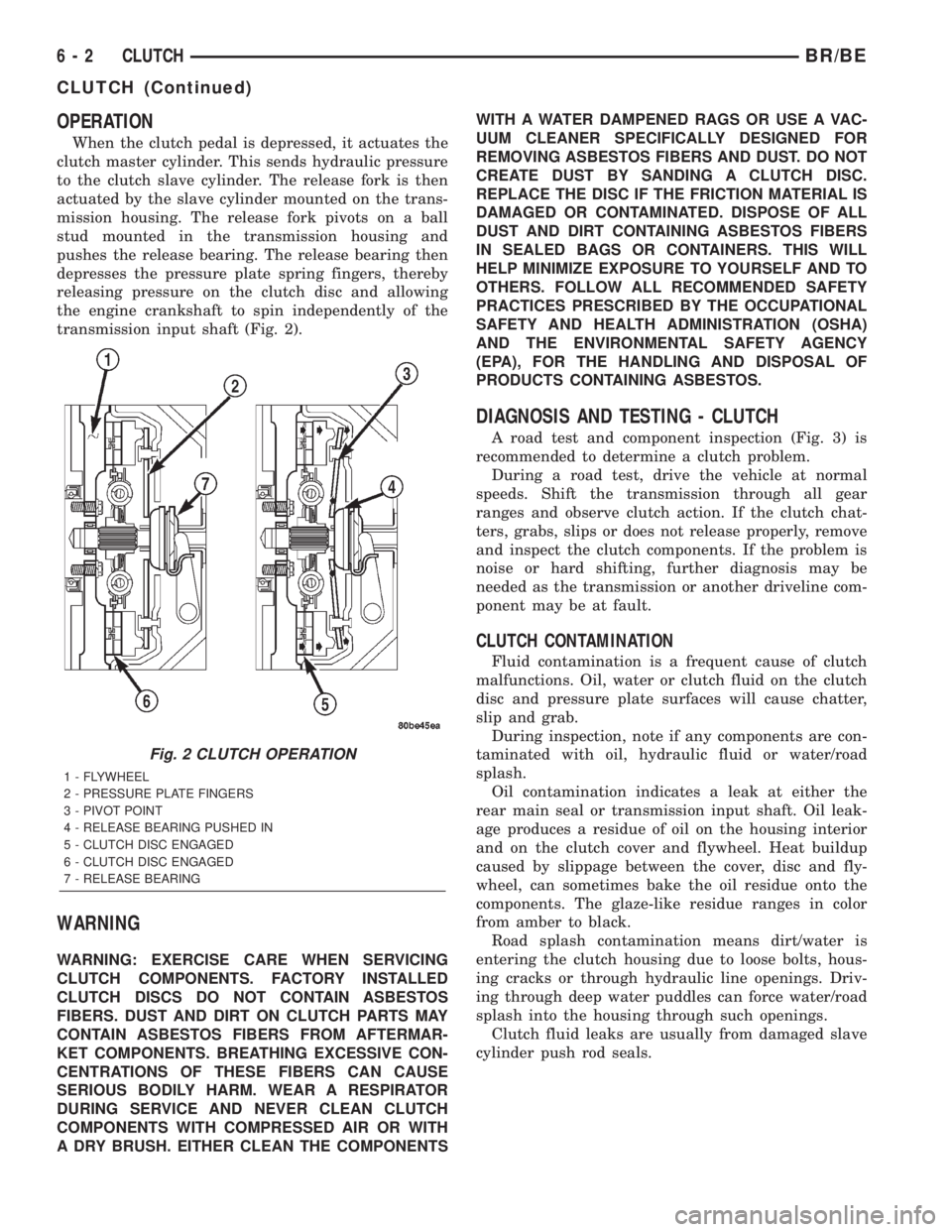
When the clutch pedal is depressed, it actuates the
clutch master cylinder. This sends hydraulic pressure
to the clutch slave cylinder. The release fork is then
actuated by the slave cylinder mounted on the trans-
mission housing. The release fork pivots on a ball
stud mounted in the transmission housing and
pushes the release bearing. The release bearing then
depresses the pressure plate spring fingers, thereby
releasing pressure on the clutch disc and allowing
the engine crankshaft to spin independently of the
transmission input shaft (Fig. 2).
WARNING
WARNING: EXERCISE CARE WHEN SERVICING
CLUTCH COMPONENTS. FACTORY INSTALLED
CLUTCH DISCS DO NOT CONTAIN ASBESTOS
FIBERS. DUST AND DIRT ON CLUTCH PARTS MAY
CONTAIN ASBESTOS FIBERS FROM AFTERMAR-
KET COMPONENTS. BREATHING EXCESSIVE CON-
CENTRATIONS OF THESE FIBERS CAN CAUSE
SERIOUS BODILY HARM. WEAR A RESPIRATOR
DURING SERVICE AND NEVER CLEAN CLUTCH
COMPONENTS WITH COMPRESSED AIR OR WITH
A DRY BRUSH. EITHER CLEAN THE COMPONENTSWITH A WATER DAMPENED RAGS OR USE A VAC-
UUM CLEANER SPECIFICALLY DESIGNED FOR
REMOVING ASBESTOS FIBERS AND DUST. DO NOT
CREATE DUST BY SANDING A CLUTCH DISC.
REPLACE THE DISC IF THE FRICTION MATERIAL IS
DAMAGED OR CONTAMINATED. DISPOSE OF ALL
DUST AND DIRT CONTAINING ASBESTOS FIBERS
IN SEALED BAGS OR CONTAINERS. THIS WILL
HELP MINIMIZE EXPOSURE TO YOURSELF AND TO
OTHERS. FOLLOW ALL RECOMMENDED SAFETY
PRACTICES PRESCRIBED BY THE OCCUPATIONAL
SAFETY AND HEALTH ADMINISTRATION (OSHA)
AND THE ENVIRONMENTAL SAFETY AGENCY
(EPA), FOR THE HANDLING AND DISPOSAL OF
PRODUCTS CONTAINING ASBESTOS.
DIAGNOSIS AND TESTING - CLUTCH
A road test and component inspection (Fig. 3) is
recommended to determine a clutch problem.
During a road test, drive the vehicle at normal
speeds. Shift the transmission through all gear
ranges and observe clutch action. If the clutch chat-
ters, grabs, slips or does not release properly, remove
and inspect the clutch components. If the problem is
noise or hard shifting, further diagnosis may be
needed as the transmission or another driveline com-
ponent may be at fault.
CLUTCH CONTAMINATION
Fluid contamination is a frequent cause of clutch
malfunctions. Oil, water or clutch fluid on the clutch
disc and pressure plate surfaces will cause chatter,
slip and grab.
During inspection, note if any components are con-
taminated with oil, hydraulic fluid or water/road
splash.
Oil contamination indicates a leak at either the
rear main seal or transmission input shaft. Oil leak-
age produces a residue of oil on the housing interior
and on the clutch cover and flywheel. Heat buildup
caused by slippage between the cover, disc and fly-
wheel, can sometimes bake the oil residue onto the
components. The glaze-like residue ranges in color
from amber to black.
Road splash contamination means dirt/water is
entering the clutch housing due to loose bolts, hous-
ing cracks or through hydraulic line openings. Driv-
ing through deep water puddles can force water/road
splash into the housing through such openings.
Clutch fluid leaks are usually from damaged slave
cylinder push rod seals.
Fig. 2 CLUTCH OPERATION
1 - FLYWHEEL
2 - PRESSURE PLATE FINGERS
3 - PIVOT POINT
4 - RELEASE BEARING PUSHED IN
5 - CLUTCH DISC ENGAGED
6 - CLUTCH DISC ENGAGED
7 - RELEASE BEARING
6 - 2 CLUTCHBR/BE
CLUTCH (Continued)
Page 235 of 2255
IMPROPER RELEASE OR CLUTCH ENGAGEMENT
Clutch release or engagement problems are caused
by wear or damage to one or more clutch compo-
nents. A visual inspection of the release components
will usually reveal the problem part.
Release problems can result in hard shifting and
noise. Items to look for are: leaks at the clutch cylin-
ders and interconnecting line; loose slave cylinder
bolts; worn/loose release fork and pivot stud; dam-
aged release bearing; and a worn clutch disc, or pres-
sure plate.
Normal condensation in vehicles that are stored or
out of service for long periods of time can generate
enough corrosion to make the disc stick to the fly-
wheel, or pressure plate. If this condition is experi-
enced, correction only requires that the disc be
loosened manually through the inspection plate open-
ing.
Engagement problems usually result in slip, chat-
ter/shudder, and noisy operation. The primary causes
are clutch disc contamination; clutch disc wear; mis-
alignment, or distortion; flywheel damage; or a com-
bination of the foregoing. A visual inspection is
required to determine the part actually causing the
problem.
CLUTCH MISALIGNMENT
Clutch components must be in proper alignment
with the crankshaft and transmission input shaft.
Misalignment caused by excessive runout or warpage
of any clutch component will cause grab, chatter and
improper clutch release.
CLUTCH COVER AND DISC RUNOUT
Check the clutch disc before installation. Axial
(face) runout of anewdisc should not exceed 0.50
mm (0.020 in.). Measure runout about 6 mm (1/4 in.)
from the outer edge of the disc facing. Obtain
another disc if runout is excessive.
Check condition of the clutch before installation. A
warped cover or diaphragm spring will cause grab
and incomplete release or engagement. Be careful
when handling the cover and disc. Impact can distort
the cover, diaphragm spring, release fingers and the
hub of the clutch disc.
Use an alignment tool when positioning the disc on
the flywheel. The tool prevents accidental misalign-
ment which could result in cover distortion and disc
damage.
A frequent cause of clutch cover distortion (and
consequent misalignment) is improper bolt tighten-
ing.
DIAGNOSIS CHART
The clutch inspection chart (Fig. 3) outlines items
to be checked before and during clutch installation.
Use the chart as a check list to help avoid overlook-
ing potential problem sources during service opera-
tions.
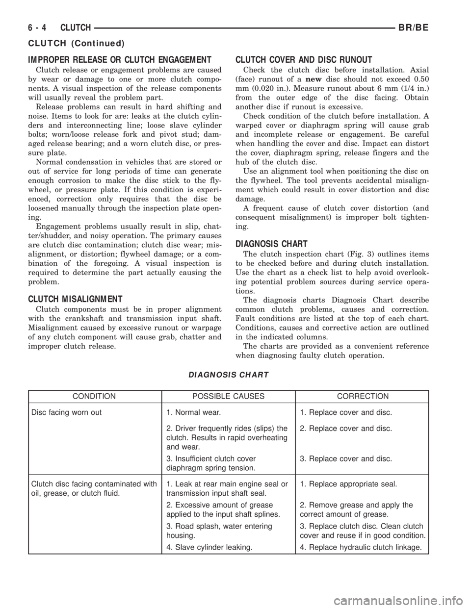
The diagnosis charts Diagnosis Chart describe
common clutch problems, causes and correction.
Fault conditions are listed at the top of each chart.
Conditions, causes and corrective action are outlined
in the indicated columns.
The charts are provided as a convenient reference
when diagnosing faulty clutch operation.
DIAGNOSIS CHART
CONDITION POSSIBLE CAUSES CORRECTION
Disc facing worn out 1. Normal wear. 1. Replace cover and disc.
2. Driver frequently rides (slips) the
clutch. Results in rapid overheating
and wear.2. Replace cover and disc.
3. Insufficient clutch cover
diaphragm spring tension.3. Replace cover and disc.
Clutch disc facing contaminated with
oil, grease, or clutch fluid.1. Leak at rear main engine seal or
transmission input shaft seal.1. Replace appropriate seal.
2. Excessive amount of grease
applied to the input shaft splines.2. Remove grease and apply the
correct amount of grease.
3. Road splash, water entering
housing.3. Replace clutch disc. Clean clutch
cover and reuse if in good condition.
4. Slave cylinder leaking. 4. Replace hydraulic clutch linkage.
6 - 4 CLUTCHBR/BE
CLUTCH (Continued)
Page 240 of 2255
CLUTCH HOUSING
DIAGNOSIS AND TESTING - CLUTCH HOUSING
The clutch housing maintains alignment between
the crankshaft and transmission input shaft. Mis-
alignment can cause clutch noise, hard shifting,
incomplete release and chatter. Also premature pilot
bearing, cover release fingers and clutch disc wear.
In severe cases, it can cause premature wear of the
transmission input shaft and front bearing.
NOTE: Only the NV4500 clutch housing can be
checked using the following bore and face runout
procedures. The NV5600 clutch housing is a inte-
gral part of the transmission and can only be
checked off the vehicle.
CLUTCH HOUSING BORE RUNOUT
CAUTION: On diesel engines if housing bore runout
exceeds 0.015 inch, the clutch housing/transmis-
sion adapter plate must be replaced. On gas
engines if housing bore runout exceeds 0.053 in.
the clutch housing must be replaced.
NOTE: Offset dowels are available for gas engines
to correct housing bore runout. They are not avail-
able for diesel engines.
(1) Remove the clutch housing and strut.
(2) Remove the clutch cover and disc.
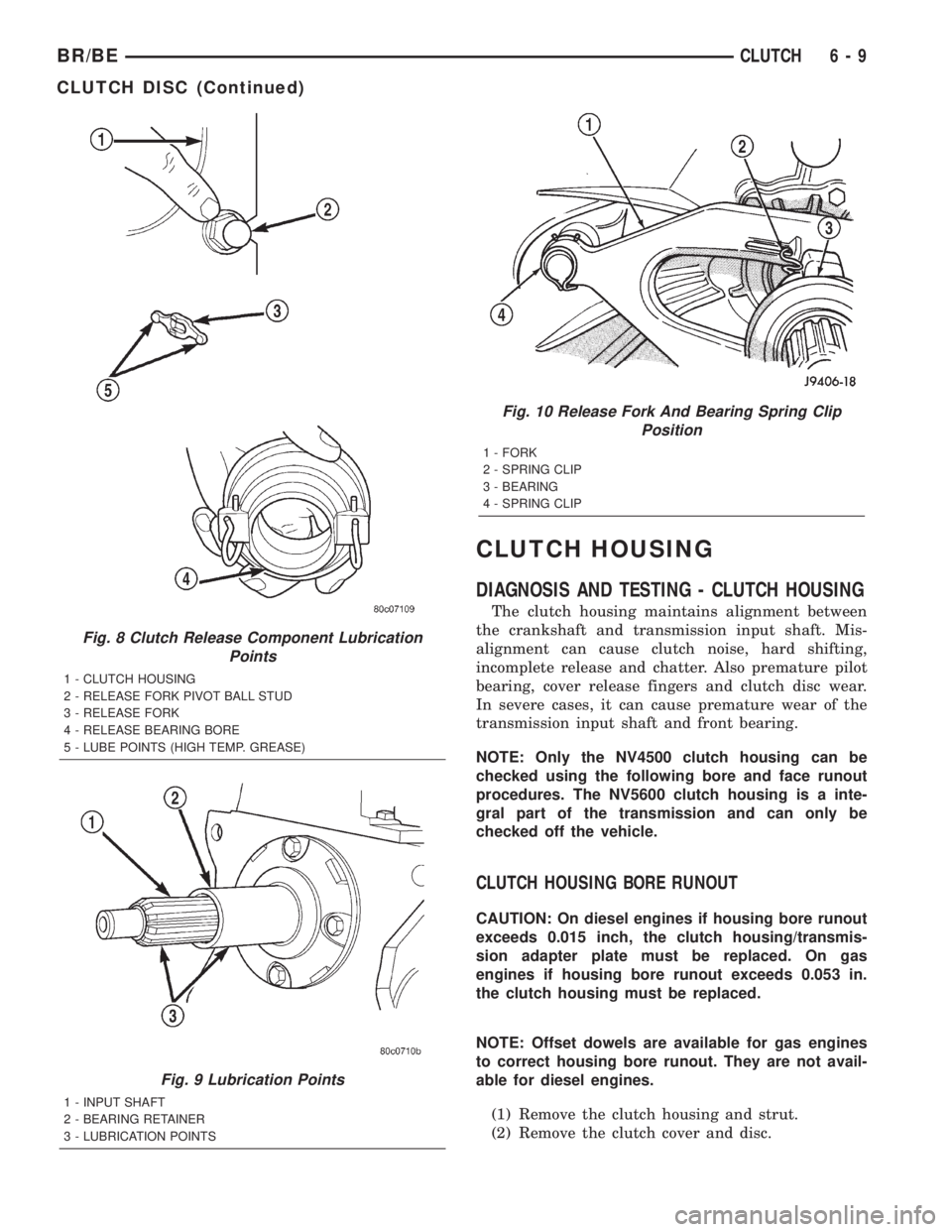
Fig. 8 Clutch Release Component Lubrication
Points
1 - CLUTCH HOUSING
2 - RELEASE FORK PIVOT BALL STUD
3 - RELEASE FORK
4 - RELEASE BEARING BORE
5 - LUBE POINTS (HIGH TEMP. GREASE)
Fig. 9 Lubrication Points
1 - INPUT SHAFT
2 - BEARING RETAINER
3 - LUBRICATION POINTS
Fig. 10 Release Fork And Bearing Spring Clip
Position
1 - FORK
2 - SPRING CLIP
3 - BEARING
4 - SPRING CLIP
BR/BECLUTCH 6 - 9
CLUTCH DISC (Continued)
Page 241 of 2255
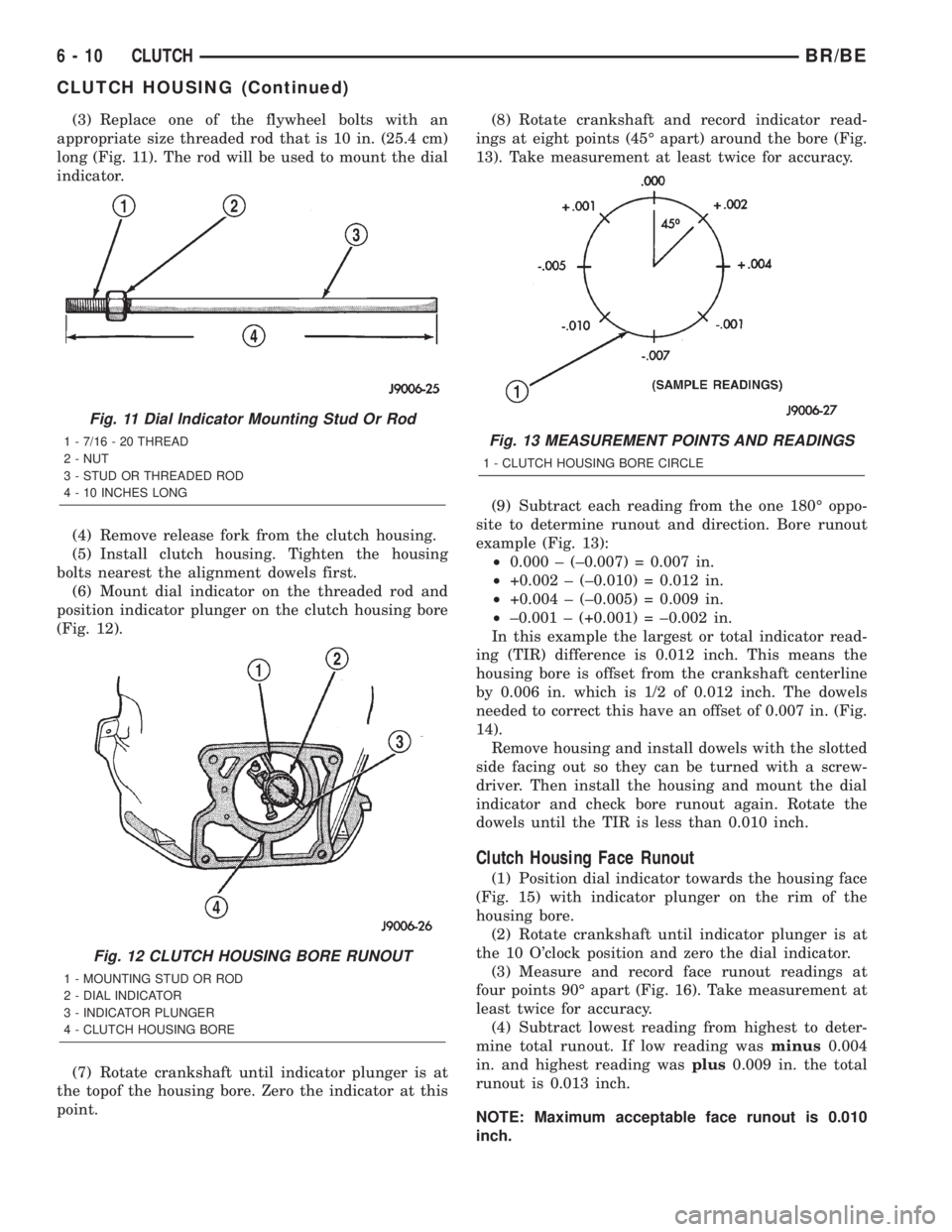
(3) Replace one of the flywheel bolts with an
appropriate size threaded rod that is 10 in. (25.4 cm)
long (Fig. 11). The rod will be used to mount the dial
indicator.
(4) Remove release fork from the clutch housing.
(5) Install clutch housing. Tighten the housing
bolts nearest the alignment dowels first.
(6) Mount dial indicator on the threaded rod and
position indicator plunger on the clutch housing bore
(Fig. 12).
(7) Rotate crankshaft until indicator plunger is at
the topof the housing bore. Zero the indicator at this
point.(8) Rotate crankshaft and record indicator read-
ings at eight points (45É apart) around the bore (Fig.
13). Take measurement at least twice for accuracy.
(9) Subtract each reading from the one 180É oppo-
site to determine runout and direction. Bore runout
example (Fig. 13):
²0.000 ± (±0.007) = 0.007 in.
²+0.002 ± (±0.010) = 0.012 in.
²+0.004 ± (±0.005) = 0.009 in.
²±0.001 ± (+0.001) = ±0.002 in.
In this example the largest or total indicator read-
ing (TIR) difference is 0.012 inch. This means the
housing bore is offset from the crankshaft centerline
by 0.006 in. which is 1/2 of 0.012 inch. The dowels
needed to correct this have an offset of 0.007 in. (Fig.
14).
Remove housing and install dowels with the slotted
side facing out so they can be turned with a screw-
driver. Then install the housing and mount the dial
indicator and check bore runout again. Rotate the
dowels until the TIR is less than 0.010 inch.
Clutch Housing Face Runout
(1) Position dial indicator towards the housing face
(Fig. 15) with indicator plunger on the rim of the
housing bore.
(2) Rotate crankshaft until indicator plunger is at
the 10 O'clock position and zero the dial indicator.
(3) Measure and record face runout readings at
four points 90É apart (Fig. 16). Take measurement at
least twice for accuracy.
(4) Subtract lowest reading from highest to deter-
mine total runout. If low reading wasminus0.004
in. and highest reading wasplus0.009 in. the total
runout is 0.013 inch.
NOTE: Maximum acceptable face runout is 0.010
inch.
Fig. 11 Dial Indicator Mounting Stud Or Rod
1 - 7/16 - 20 THREAD
2 - NUT
3 - STUD OR THREADED ROD
4 - 10 INCHES LONG
Fig. 12 CLUTCH HOUSING BORE RUNOUT
1 - MOUNTING STUD OR ROD
2 - DIAL INDICATOR
3 - INDICATOR PLUNGER
4 - CLUTCH HOUSING BORE
Fig. 13 MEASUREMENT POINTS AND READINGS
1 - CLUTCH HOUSING BORE CIRCLE
6 - 10 CLUTCHBR/BE
CLUTCH HOUSING (Continued)
Page 244 of 2255
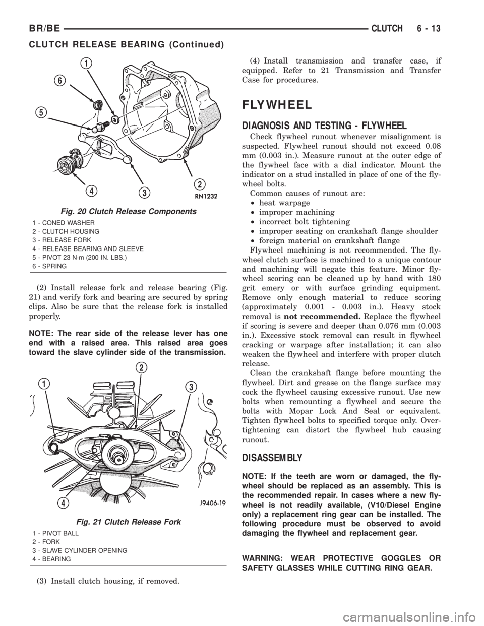
(2) Install release fork and release bearing (Fig.
21) and verify fork and bearing are secured by spring
clips. Also be sure that the release fork is installed
properly.
NOTE: The rear side of the release lever has one
end with a raised area. This raised area goes
toward the slave cylinder side of the transmission.
(3) Install clutch housing, if removed.(4) Install transmission and transfer case, if
equipped. Refer to 21 Transmission and Transfer
Case for procedures.
FLYWHEEL
DIAGNOSIS AND TESTING - FLYWHEEL
Check flywheel runout whenever misalignment is
suspected. Flywheel runout should not exceed 0.08
mm (0.003 in.). Measure runout at the outer edge of
the flywheel face with a dial indicator. Mount the
indicator on a stud installed in place of one of the fly-
wheel bolts.
Common causes of runout are:
²heat warpage
²improper machining
²incorrect bolt tightening
²improper seating on crankshaft flange shoulder
²foreign material on crankshaft flange
Flywheel machining is not recommended. The fly-
wheel clutch surface is machined to a unique contour
and machining will negate this feature. Minor fly-
wheel scoring can be cleaned up by hand with 180
grit emery or with surface grinding equipment.
Remove only enough material to reduce scoring
(approximately 0.001 - 0.003 in.). Heavy stock
removal isnot recommended.Replace the flywheel
if scoring is severe and deeper than 0.076 mm (0.003
in.). Excessive stock removal can result in flywheel
cracking or warpage after installation; it can also
weaken the flywheel and interfere with proper clutch
release.
Clean the crankshaft flange before mounting the
flywheel. Dirt and grease on the flange surface may
cock the flywheel causing excessive runout. Use new
bolts when remounting a flywheel and secure the
bolts with Mopar Lock And Seal or equivalent.
Tighten flywheel bolts to specified torque only. Over-
tightening can distort the flywheel hub causing
runout.
DISASSEMBLY
NOTE: If the teeth are worn or damaged, the fly-
wheel should be replaced as an assembly. This is
the recommended repair. In cases where a new fly-
wheel is not readily available, (V10/Diesel Engine
only) a replacement ring gear can be installed. The
following procedure must be observed to avoid
damaging the flywheel and replacement gear.
WARNING: WEAR PROTECTIVE GOGGLES OR
SAFETY GLASSES WHILE CUTTING RING GEAR.
Fig. 20 Clutch Release Components
1 - CONED WASHER
2 - CLUTCH HOUSING
3 - RELEASE FORK
4 - RELEASE BEARING AND SLEEVE
5 - PIVOT 23 N´m (200 IN. LBS.)
6 - SPRING
Fig. 21 Clutch Release Fork
1 - PIVOT BALL
2 - FORK
3 - SLAVE CYLINDER OPENING
4 - BEARING
BR/BECLUTCH 6 - 13
CLUTCH RELEASE BEARING (Continued)
Page 275 of 2255
REMOVAL
NOTE: The belt routing schematics are published
from the latest information available at the time of
publication. If anything differs between these sche-
matics and the Belt Routing Label, use the sche-
matics on Belt Routing Label. This label is located
in the engine compartment.
CAUTION: Do not attempt to check belt tension with
a belt tension gauge on vehicles equipped with an
automatic belt tensioner. Refer to Automatic Belt
Tensioner in this group.
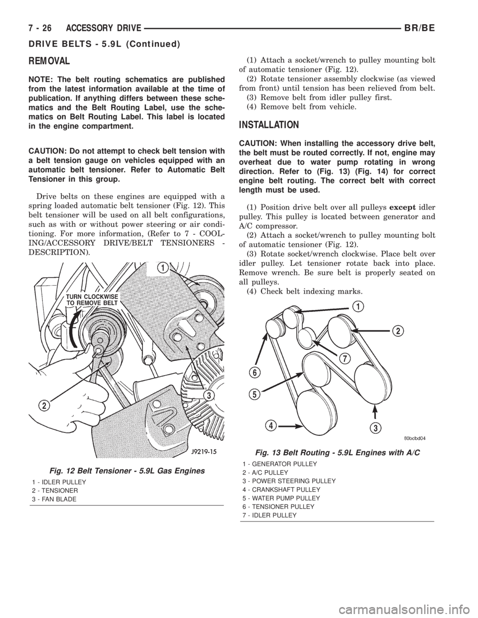
Drive belts on these engines are equipped with a
spring loaded automatic belt tensioner (Fig. 12). This
belt tensioner will be used on all belt configurations,
such as with or without power steering or air condi-
tioning. For more information, (Refer to 7 - COOL-
ING/ACCESSORY DRIVE/BELT TENSIONERS -
DESCRIPTION).(1) Attach a socket/wrench to pulley mounting bolt
of automatic tensioner (Fig. 12).
(2) Rotate tensioner assembly clockwise (as viewed
from front) until tension has been relieved from belt.
(3) Remove belt from idler pulley first.
(4) Remove belt from vehicle.
INSTALLATION
CAUTION: When installing the accessory drive belt,
the belt must be routed correctly. If not, engine may
overheat due to water pump rotating in wrong
direction. Refer to (Fig. 13) (Fig. 14) for correct
engine belt routing. The correct belt with correct
length must be used.
(1) Position drive belt over all pulleysexceptidler
pulley. This pulley is located between generator and
A/C compressor.
(2) Attach a socket/wrench to pulley mounting bolt
of automatic tensioner (Fig. 12).
(3) Rotate socket/wrench clockwise. Place belt over
idler pulley. Let tensioner rotate back into place.
Remove wrench. Be sure belt is properly seated on
all pulleys.
(4) Check belt indexing marks.
Fig. 12 Belt Tensioner - 5.9L Gas Engines
1 - IDLER PULLEY
2 - TENSIONER
3 - FAN BLADE
Fig. 13 Belt Routing - 5.9L Engines with A/C
1 - GENERATOR PULLEY
2 - A/C PULLEY
3 - POWER STEERING PULLEY
4 - CRANKSHAFT PULLEY
5 - WATER PUMP PULLEY
6 - TENSIONER PULLEY
7 - IDLER PULLEY
7 - 26 ACCESSORY DRIVEBR/BE
DRIVE BELTS - 5.9L (Continued)
Page 276 of 2255
DRIVE BELTS - 8.0L
DIAGNOSIS AND TESTINGÐACCESSORY
DRIVE BELT
VISUAL DIAGNOSIS
When diagnosing serpentine accessory drive belts,
small cracks that run across the ribbed surface of the
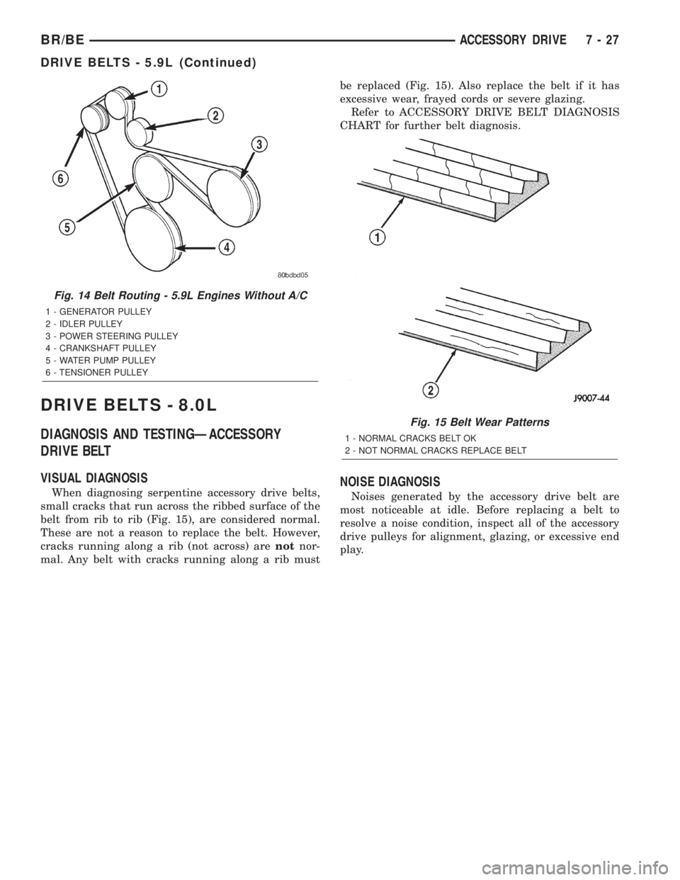
belt from rib to rib (Fig. 15), are considered normal.
These are not a reason to replace the belt. However,
cracks running along a rib (not across) arenotnor-
mal. Any belt with cracks running along a rib mustbe replaced (Fig. 15). Also replace the belt if it has
excessive wear, frayed cords or severe glazing.
Refer to ACCESSORY DRIVE BELT DIAGNOSIS
CHART for further belt diagnosis.NOISE DIAGNOSIS
Noises generated by the accessory drive belt are
most noticeable at idle. Before replacing a belt to
resolve a noise condition, inspect all of the accessory
drive pulleys for alignment, glazing, or excessive end
play.
Fig. 14 Belt Routing - 5.9L Engines Without A/C
1 - GENERATOR PULLEY
2 - IDLER PULLEY
3 - POWER STEERING PULLEY
4 - CRANKSHAFT PULLEY
5 - WATER PUMP PULLEY
6 - TENSIONER PULLEY
Fig. 15 Belt Wear Patterns
1 - NORMAL CRACKS BELT OK
2 - NOT NORMAL CRACKS REPLACE BELT
BR/BEACCESSORY DRIVE 7 - 27
DRIVE BELTS - 5.9L (Continued)
Page 279 of 2255
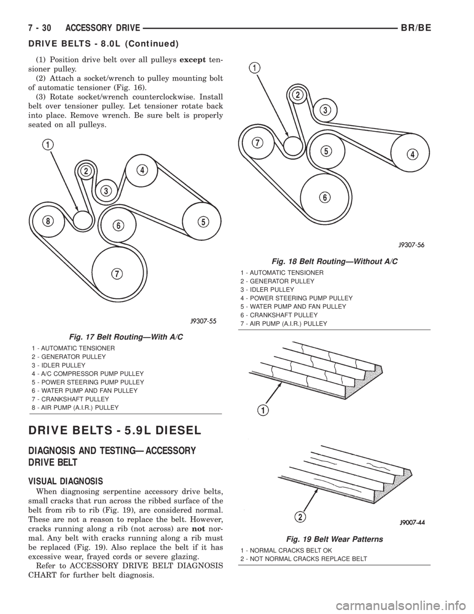
(1) Position drive belt over all pulleysexceptten-
sioner pulley.
(2) Attach a socket/wrench to pulley mounting bolt
of automatic tensioner (Fig. 16).
(3) Rotate socket/wrench counterclockwise. Install
belt over tensioner pulley. Let tensioner rotate back
into place. Remove wrench. Be sure belt is properly
seated on all pulleys.
DRIVE BELTS - 5.9L DIESEL
DIAGNOSIS AND TESTINGÐACCESSORY
DRIVE BELT
VISUAL DIAGNOSIS
When diagnosing serpentine accessory drive belts,
small cracks that run across the ribbed surface of the
belt from rib to rib (Fig. 19), are considered normal.
These are not a reason to replace the belt. However,
cracks running along a rib (not across) arenotnor-
mal. Any belt with cracks running along a rib must
be replaced (Fig. 19). Also replace the belt if it has
excessive wear, frayed cords or severe glazing.
Refer to ACCESSORY DRIVE BELT DIAGNOSIS
CHART for further belt diagnosis.
Fig. 17 Belt RoutingÐWith A/C
1 - AUTOMATIC TENSIONER
2 - GENERATOR PULLEY
3 - IDLER PULLEY
4 - A/C COMPRESSOR PUMP PULLEY
5 - POWER STEERING PUMP PULLEY
6 - WATER PUMP AND FAN PULLEY
7 - CRANKSHAFT PULLEY
8 - AIR PUMP (A.I.R.) PULLEY
Fig. 18 Belt RoutingÐWithout A/C
1 - AUTOMATIC TENSIONER
2 - GENERATOR PULLEY
3 - IDLER PULLEY
4 - POWER STEERING PUMP PULLEY
5 - WATER PUMP AND FAN PULLEY
6 - CRANKSHAFT PULLEY
7 - AIR PUMP (A.I.R.) PULLEY
Fig. 19 Belt Wear Patterns
1 - NORMAL CRACKS BELT OK
2 - NOT NORMAL CRACKS REPLACE BELT
7 - 30 ACCESSORY DRIVEBR/BE
DRIVE BELTS - 8.0L (Continued)
Page 282 of 2255
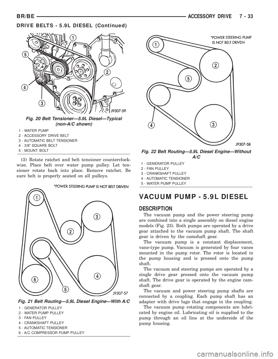
(3) Rotate ratchet and belt tensioner counterclock-
wise. Place belt over water pump pulley. Let ten-
sioner rotate back into place. Remove ratchet. Be
sure belt is properly seated on all pulleys.
VACUUM PUMP - 5.9L DIESEL
DESCRIPTION
The vacuum pump and the power steering pump
are combined into a single assembly on diesel engine
models (Fig. 23). Both pumps are operated by a drive
gear attached to the vacuum pump shaft. The shaft
gear is driven by the camshaft gear.
The vacuum pump is a constant displacement,
vane-type pump. Vacuum is generated by four vanes
mounted in the pump rotor. The rotor is located in
the pump housing and is pressed onto the pump
shaft.
The vacuum and steering pumps are operated by a
single drive gear pressed onto the vacuum pump
shaft. The drive gear is operated by the engine cam-
shaft gear.
The vacuum and power steering pump shafts are
connected by a coupling. Each pump shaft has an
adapter with drive lugs that engage in the coupling.
The vacuum pump rotating components are lubri-
cated by engine oil. Lubricating oil is supplied to the
pump through an oil line at the underside of the
pump housing.
Fig. 20 Belt TensionerÐ5.9L DieselÐTypical
(non-A/C shown)
1 - WATER PUMP
2 - ACCESSORY DRIVE BELT
3 - AUTOMATIC BELT TENSIONER
4 - 3/89SQUARE BOLT
5 - MOUNT. BOLT
Fig. 21 Belt RoutingÐ5.9L Diesel EngineÐWith A/C
1 - GENERATOR PULLEY
2 - WATER PUMP PULLEY
3 - FAN PULLEY
4 - CRANKSHAFT PULLEY
5 - AUTOMATIC TENSIONER
6 - A/C COMPRESSOR PUMP PULLEY
Fig. 22 Belt RoutingÐ5.9L Diesel EngineÐWithout
A/C
1 - GENERATOR PULLEY
2 - FAN PULLEY
3 - CRANKSHAFT PULLEY
4 - AUTOMATIC TENSIONER
5 - WATER PUMP PULLEY
BR/BEACCESSORY DRIVE 7 - 33
DRIVE BELTS - 5.9L DIESEL (Continued)