battery location DODGE RAM 2002 Service Repair Manual
[x] Cancel search | Manufacturer: DODGE, Model Year: 2002, Model line: RAM, Model: DODGE RAM 2002Pages: 2255, PDF Size: 62.07 MB
Page 315 of 2255
INSPECTION
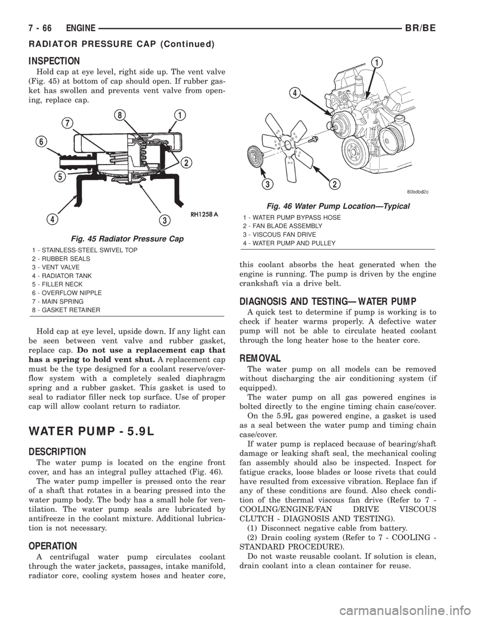
Hold cap at eye level, right side up. The vent valve
(Fig. 45) at bottom of cap should open. If rubber gas-
ket has swollen and prevents vent valve from open-
ing, replace cap.
Hold cap at eye level, upside down. If any light can
be seen between vent valve and rubber gasket,
replace cap.Do not use a replacement cap that
has a spring to hold vent shut.A replacement cap
must be the type designed for a coolant reserve/over-
flow system with a completely sealed diaphragm
spring and a rubber gasket. This gasket is used to
seal to radiator filler neck top surface. Use of proper
cap will allow coolant return to radiator.
WATER PUMP - 5.9L
DESCRIPTION
The water pump is located on the engine front
cover, and has an integral pulley attached (Fig. 46).
The water pump impeller is pressed onto the rear
of a shaft that rotates in a bearing pressed into the
water pump body. The body has a small hole for ven-
tilation. The water pump seals are lubricated by
antifreeze in the coolant mixture. Additional lubrica-
tion is not necessary.
OPERATION
A centrifugal water pump circulates coolant
through the water jackets, passages, intake manifold,
radiator core, cooling system hoses and heater core,this coolant absorbs the heat generated when the
engine is running. The pump is driven by the engine
crankshaft via a drive belt.
DIAGNOSIS AND TESTINGÐWATER PUMP
A quick test to determine if pump is working is to
check if heater warms properly. A defective water
pump will not be able to circulate heated coolant
through the long heater hose to the heater core.
REMOVAL
The water pump on all models can be removed
without discharging the air conditioning system (if
equipped).
The water pump on all gas powered engines is
bolted directly to the engine timing chain case/cover.
On the 5.9L gas powered engine, a gasket is used
as a seal between the water pump and timing chain
case/cover.
If water pump is replaced because of bearing/shaft
damage or leaking shaft seal, the mechanical cooling
fan assembly should also be inspected. Inspect for
fatigue cracks, loose blades or loose rivets that could
have resulted from excessive vibration. Replace fan if
any of these conditions are found. Also check condi-
tion of the thermal viscous fan drive (Refer to 7 -
COOLING/ENGINE/FAN DRIVE VISCOUS
CLUTCH - DIAGNOSIS AND TESTING).
(1) Disconnect negative cable from battery.
(2) Drain cooling system (Refer to 7 - COOLING -
STANDARD PROCEDURE).
Do not waste reusable coolant. If solution is clean,
drain coolant into a clean container for reuse.
Fig. 45 Radiator Pressure Cap
1 - STAINLESS-STEEL SWIVEL TOP
2 - RUBBER SEALS
3 - VENT VALVE
4 - RADIATOR TANK
5 - FILLER NECK
6 - OVERFLOW NIPPLE
7 - MAIN SPRING
8 - GASKET RETAINER
Fig. 46 Water Pump LocationÐTypical
1 - WATER PUMP BYPASS HOSE
2 - FAN BLADE ASSEMBLY
3 - VISCOUS FAN DRIVE
4 - WATER PUMP AND PULLEY
7 - 66 ENGINEBR/BE
RADIATOR PRESSURE CAP (Continued)
Page 338 of 2255
AUDIO
TABLE OF CONTENTS
page page
AUDIO
DESCRIPTION..........................1
OPERATION............................2
DIAGNOSIS AND TESTING - AUDIO..........2
SPECIAL TOOLS
AUDIO SYSTEMS......................4
ANTENNA BODY & CABLE
DESCRIPTION..........................4
OPERATION............................4
DIAGNOSIS AND TESTING - ANTENNA.......5
REMOVAL.............................6
INSTALLATION..........................6
RADIO CHOKE RELAY
DESCRIPTION..........................7
OPERATION............................8
DIAGNOSIS AND TESTING - RADIO CHOKE
RELAY...............................8
REMOVAL.............................8
INSTALLATION..........................9
INSTRUMENT PANEL ANTENNA CABLE
REMOVAL.............................9
INSTALLATION..........................9
RADIO
DESCRIPTION.........................10
OPERATION...........................10
DIAGNOSIS AND TESTING - RADIO.........10
REMOVAL.............................11
INSTALLATION.........................11
RADIO NOISE SUPPRESSION COMPONENTS
DESCRIPTION.........................12
DIAGNOSIS AND TESTING - RADIO NOISE
SUPPRESSION COMPONENTS...........12ENGINE-TO-BODY GROUND STRAP
REMOVAL.............................12
INSTALLATION.........................13
CAB-TO- BED GROUND STRAP
REMOVAL.............................13
INSTALLATION.........................14
HEATER CORE GROUND STRAP
REMOVAL.............................14
INSTALLATION.........................14
REMOTE SWITCHES
DESCRIPTION.........................14
OPERATION...........................15
DIAGNOSIS AND TESTING - REMOTE
SWITCHES..........................15
REMOVAL.............................16
INSTALLATION.........................16
SPEAKER
DESCRIPTION.........................17
OPERATION...........................17
DIAGNOSIS AND TESTING - SPEAKER......17
A-PILLAR TWEETER SPEAKER
REMOVAL.............................18
INSTALLATION.........................19
FRONT DOOR SPEAKER
REMOVAL.............................19
INSTALLATION.........................19
REAR CAB SIDE PANEL SPEAKER
REMOVAL.............................20
INSTALLATION.........................20
REAR DOOR SPEAKER
REMOVAL.............................20
INSTALLATION.........................21
AUDIO
DESCRIPTION
An audio system is standard factory-installed
equipment on this model, unless the vehicle is
ordered with an available radio delete option. The
standard equipment audio system includes an
AM/FM/cassette (RAS sales code) receiver, and
speakers in four locations. Several combinations of
radio receivers and speaker systems are offered as
optional equipment on this model. The audio system
uses an ignition switched source of battery current so
that the system will only operate when the ignition
switch is in the On or Accessory positions. The audio
system includes the following components:²Antenna
²Clockspring (with remote radio switches only)
²Filter, choke and speaker relay (with premium
speaker system only)
²High-line or premium Central Timer Module
(CTM) (with remote radio switches)
²Radio noise suppression components
²Radio receiver
²Remote radio switches (optional with RAZ radio
receiver only)
²Speakers
Refer to Electrical, Restraints for more information
on the clockspring. Refer to Electrical, Body Control/
Central Control Module for more information on the
Central Timer Module. Refer to the appropriate wir-
ing information. The wiring information includes wir-
BR/BEAUDIO 8A - 1
Page 339 of 2255
ing diagrams, proper wire and connector repair
procedures, details of wire harness routing and
retention, connector pin-out information and location
views for the various wire harness connectors, splices
and grounds. Following are general descriptions of
the remaining major components in the standard and
optional factory-installed audio systems.
OPERATION
See the owner's manual in the vehicle glove box for
more information on the features, use and operation
of each of the available audio systems.
CENTRAL TIMER MODULE
The high-line or premium Central Timer Module
(CTM) can also control some features of the audio
system when the vehicle is equipped with the
optional RAZ radio receiver and remote radio
switches. A high-line CTM is used on high-line ver-
sions of this vehicle. A premium CTM is used on
vehicles equipped with the optional heated seats. The
CTM combines the functions of a chime/buzzer mod-
ule, an intermittent wipe module, an illuminated
entry module, a remote keyless entry module, and a
vehicle theft security system module in a single unit.
The high-line or premium CTM also controls and
integrates many of the additional electronic functions
and features included on models with this option.
The RAZ radio receiver with a remote radio switch
option is one of the features that the CTM controls.
The CTM is programmed to send switch status mes-sages over the Chrysler Collision Detection (CCD)
data bus to control the volume, seek, and pre-set sta-
tion advance functions of the RAZ radio receiver. The
CTM monitors the status of the remote radio
switches located on the steering wheel through a
hard wired circuit. The CTM then sends the proper
switch status messages to the radio receiver. The
electronic circuitry within the radio receiver responds
to the switch status messages it receives by adjusting
the radio settings as requested.
Refer to Electrical, Body Control/Central Timer
Module for more information on the high-line CTM.
Refer to Remote Radio Switch in Description and
Operation for more information on this component.
In addition, radio receivers connected to the CCD
data bus have several audio system functions that
can be diagnosed using a DRBIIItscan tool. Refer to
the proper Diagnostic Procedures manual for more
information on DRBIIIttesting of the audio systems.
DIAGNOSIS AND TESTING - AUDIO
WARNING: ON VEHICLES EQUIPPED WITH AIR-
BAGS, REFER TO ELECTRICAL, RESTRAINTS
BEFORE ATTEMPTING ANY STEERING WHEEL,
STEERING COLUMN, OR INSTRUMENT PANEL
COMPONENT DIAGNOSIS OR SERVICE. FAILURE
TO TAKE THE PROPER PRECAUTIONS COULD
RESULT IN ACCIDENTAL AIRBAG DEPLOYMENT
AND POSSIBLE PERSONAL INJURY.
Audio System Diagnosis
CONDITION POSSIBLE CAUSE CORRECTION
NO AUDIO 1. Fuse faulty. 1. Check radio fuses in junction block. Replace faulty
fuses, if required.
2. Radio connector faulty. 2. Check for loose or corroded radio connections. Repair,
if required.
3. Wiring faulty. 3. Check for battery voltage at radio connector. Repair
wiring, if required.
4. Ground faulty. 4. Check for continuity between radio chassis and a
known good ground. There should be continuity. Repair
ground, if required.
5. Radio faulty. 5. Refer to Radio in the Diagnosis and Testing section of
this group.
6. Speakers faulty. 6. Refer to Speaker in the Diagnosis and Testing section
of this group.
7. Amplifier faulty (if
equipped).7. Refer to Speaker in the Diagnosis and Testing section
of this group.
8A - 2 AUDIOBR/BE
AUDIO (Continued)
Page 345 of 2255
OPERATION
The filter, choke, and speaker relay unit is used to
control the supply of fused battery current to the
front door speaker-mounted dual amplifiers. The
speaker relay is energized by a fused 12 volt output
from the radio receiver whenever the radio is turned
on. For complete circuit diagrams, refer to the appro-
priate wiring information. The wiring information
includes wiring diagrams, proper wire and connector
repair procedures, details of wire harness routing
and retention, connector pin-out information and
location views for the various wire harness connec-
tors, splices and grounds.
DIAGNOSIS AND TESTING - RADIO CHOKE
RELAY
The filter, choke and speaker relay is used to
switch power to the individual speaker amplifiers
used with the Infinity premium speaker package.
The choke and relay are serviced only as a unit. If all
of the speakers are inoperative the filter, choke and
speaker relay unit should be considered suspect.
However, before replacement make the following
checks of the filter, choke and speaker relay circuits.
For complete circuit diagrams, refer to the appropri-
ate wiring information. The wiring information
includes wiring diagrams, proper wire and connector
repair procedures, details of wire harness routing
and retention, connector pin-out information and
location views for the various wire harness connec-
tors, splices and grounds.
(1) Check the fused B(+) fuse in the junction block.
If OK, go to Step 2. If not OK, replace the faulty
fuse.
(2) Check for battery voltage at the fused B(+) fuse
in the junction block. If OK, go to Step 3. If not OK,
repair the open fused B(+) circuit to the battery as
required.
(3) Disconnect the instrument panel wire harness
connector from the filter, choke and speaker relay
unit. Check for battery voltage at the fused B(+) cir-
cuit cavity of the instrument panel wire harness con-
nector for the filter, choke and speaker relay unit. If
OK, go to Step 4. If not OK, repair the open fused
B(+) circuit to the junction block fuse as required.
(4) Probe the ground circuit cavity of the instru-
ment panel wire harness connector for the filter,
choke and speaker relay unit. Check for continuity to
a good ground. There should be continuity. If OK, go
to Step 5. If not OK, repair the open ground circuit to
ground as required.
(5) Turn the ignition switch to the On position and
turn the radio on. Check for battery voltage at the
radio 12-volt output circuit cavity of the instrument
panel wire harness connector for the filter, choke and
speaker relay unit. If OK, go to Step 6. If not OK,repair the open radio 12-volt output circuit to the
radio as required.
(6) Turn the radio and ignition switches to the Off
position. Reconnect the instrument panel wire har-
ness connector to the filter, choke and speaker relay
unit. Check for battery voltage at the amplified
speaker (+) circuit cavity of the instrument panel
wire harness connector for the filter, choke and
speaker relay unit. There should be zero volts. Turn
the ignition and radio switches to the On position.
There should now be battery voltage. If OK, repair
the open amplified speaker (+) circuits to the speak-
er-mounted amplifiers as required. If not OK, replace
the faulty filter, choke and speaker relay unit.
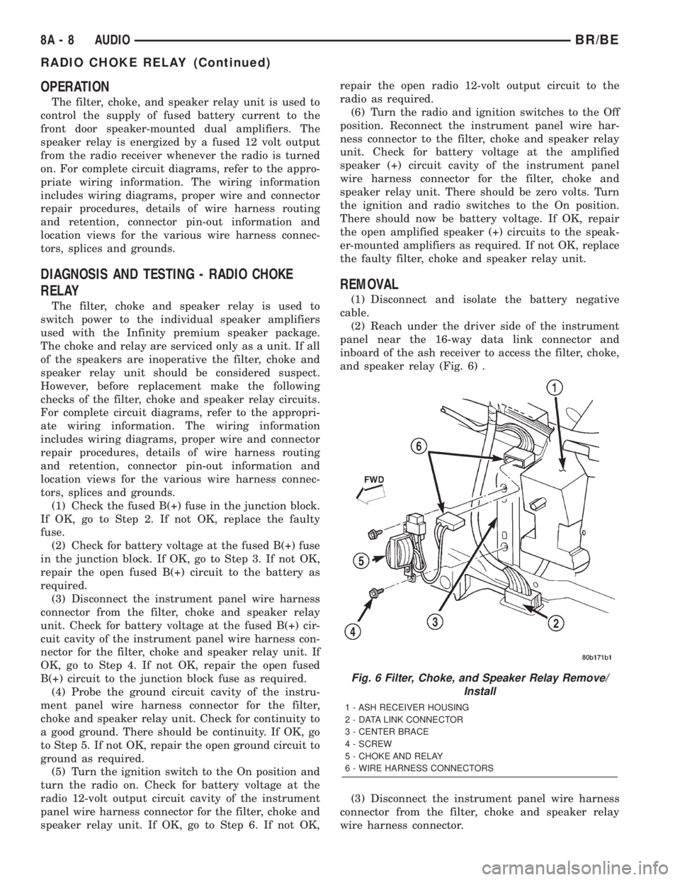
REMOVAL
(1) Disconnect and isolate the battery negative
cable.
(2) Reach under the driver side of the instrument
panel near the 16-way data link connector and
inboard of the ash receiver to access the filter, choke,
and speaker relay (Fig. 6) .
(3) Disconnect the instrument panel wire harness
connector from the filter, choke and speaker relay
wire harness connector.
Fig. 6 Filter, Choke, and Speaker Relay Remove/
Install
1 - ASH RECEIVER HOUSING
2 - DATA LINK CONNECTOR
3 - CENTER BRACE
4 - SCREW
5 - CHOKE AND RELAY
6 - WIRE HARNESS CONNECTORS
8A - 8 AUDIOBR/BE
RADIO CHOKE RELAY (Continued)
Page 347 of 2255
RADIO
DESCRIPTION
Available factory-installed radio receivers for this
model include an AM/FM/cassette (RAS sales code),
an AM/FM/CD/3-band graphic equalizer (RBR sales
code), or an AM/FM/CD/cassette/3-band graphic
equalizer (RAZ sales code). The factory-installed RAZ
sales code radio receivers can also communicate on
the Chrysler Collision Detection (CCD) data bus net-
work through a separate two-way wire harness con-
nector. All factory-installed receivers are stereo
Electronically Tuned Radios (ETR) and include an
electronic digital clock function.
These radio receivers can only be serviced by an
authorized radio repair station. See the latest War-
ranty Policies and Procedures manual for a current
listing of authorized radio repair stations.
All vehicles are equipped with an Ignition-Off
Draw (IOD) fuse that is removed when the vehicle is
shipped from the factory. This fuse feeds various
accessories that require battery current when the
ignition switch is in the Off position, including the
clock. The IOD fuse is removed to prevent battery
discharge during vehicle storage.
When removing or installing the IOD fuse, it is
important that the ignition switch be in the Off posi-
tion. Failure to place the ignition switch in the Off
position can cause the radio display to become scram-
bled when the IOD fuse is removed and replaced.
Removing and replacing the IOD fuse again, with the
ignition switch in the Off position, will correct the
scrambled display condition.
The IOD fuse should be checked if the radio or
clock displays are inoperative. The IOD fuse is
located in the junction block. Refer to the fuse layout
label on the back of the instrument panel fuse access
panel for IOD fuse identification and location.
OPERATION
The radio receiver operates on fused battery cur-
rent that is available only when the ignition switch is
in the On or Accessory positions. The electronic digi-
tal clock function of the radio operates on fused bat-
tery current supplied through the IOD fuse,
regardless of the ignition switch position.
For more information on the features, setting pro-
cedures, and control functions for each of the avail-
able factory-installed radio receivers, see the owner's
manual in the vehicle glove box. For complete circuit
diagrams, refer to the appropriate wiring informa-
tion. The wiring information includes wiring dia-
grams, proper wire and connector repair procedures,
details of wire harness routing and retention, connec-
tor pin-out information and location views for the
various wire harness connectors, splices and grounds.
DIAGNOSIS AND TESTING - RADIO
If the vehicle is equipped with the optional remote
radio switches located on the steering wheel and the
problem being diagnosed is related to one of the
symptoms listed below, be certain to check the
remote radio switches and circuits. Refer to Audio,
Remote Radio Switch prior to attempting radio diag-
nosis or repair.
²Stations changing with no remote radio switch
input
²Radio memory presets not working properly
²Volume changes with no remote radio switch
input
²Remote radio switch buttons taking on other
functions
²CD player skipping tracks
²Remote radio switch inoperative.
For complete circuit diagrams, refer to the appro-
priate wiring information. The wiring information
includes wiring diagrams, proper wire and connector
repair procedures, details of wire harness routing
and retention, connector pin-out information and
location views for the various wire harness connec-
tors, splices and grounds.
WARNING: ON VEHICLES EQUIPPED WITH AIR-
BAGS, REFER TO ELECTRICAL, RESTRAINTS
BEFORE ATTEMPTING ANY STEERING WHEEL,
STEERING COLUMN, OR INSTRUMENT PANEL
COMPONENT DIAGNOSIS OR SERVICE. FAILURE
TO TAKE THE PROPER PRECAUTIONS COULD
RESULT IN ACCIDENTAL AIRBAG DEPLOYMENT
AND POSSIBLE PERSONAL INJURY.
CAUTION: The speaker output of the radio receiver
is a ªfloating groundº system. Do not allow any
speaker lead to short to ground, as damage to the
radio receiver may result.
(1) Check the fused B(+) fuse in the junction block.
If OK, go to Step 2. If not OK, repair the shorted cir-
cuit or component as required and replace the faulty
fuse.
(2) Check for battery voltage at the fused B(+) fuse
in the junction block. If OK, go to Step 3. If not OK,
repair the open fused B(+) circuit to the Power Dis-
tribution Center (PDC) as required.
(3) Check the fused ignition switch output (acc/
run) fuse in the junction block. If OK, go to Step 4. If
not OK, repair the shorted circuit or component as
required and replace the faulty fuse(s).
(4) Turn the ignition switch to the On position.
Check for battery voltage at the fused ignition switch
output (acc/run) fuse in the junction block. If OK, go
to Step 5. If not OK, repair the open fused ignition
8A - 10 AUDIOBR/BE
Page 349 of 2255
RADIO NOISE SUPPRESSION
COMPONENTS
DESCRIPTION
Radio Frequency Interference (RFI) and Electro-
Magnetic Interference (EMI) noise suppression is
accomplished primarily through circuitry internal to
the radio receivers. These internal suppression
devices are only serviced as part of the radio receiver.
External suppression devices that are used on this
vehicle to control RFI or EMI noise include the fol-
lowing:
²Radio antenna base ground
²Radio receiver chassis ground wire or strap
²Engine-to-body ground straps
²Cab-to-bed ground strap
²Heater core ground strap
²Resistor-type spark plugs
²Radio suppression-type secondary ignition wir-
ing.
For more information on the spark plugs and sec-
ondary ignition components, refer to Electrical, Igni-
tion Control.
DIAGNOSIS AND TESTING - RADIO NOISE
SUPPRESSION COMPONENTS
WARNING: ON VEHICLES EQUIPPED WITH AIR-
BAGS, REFER TO ELECTRICAL, RESTRAINTS
BEFORE ATTEMPTING ANY STEERING WHEEL,
STEERING COLUMN, OR INSTRUMENT PANEL
COMPONENT DIAGNOSIS OR SERVICE. FAILURE
TO TAKE THE PROPER PRECAUTIONS COULD
RESULT IN ACCIDENTAL AIRBAG DEPLOYMENT
AND POSSIBLE PERSONAL INJURY.
For complete circuit diagrams, refer to the appro-
priate wiring information. The wiring information
includes wiring diagrams, proper wire and connector
repair procedures, details of wire harness routing
and retention, connector pin-out information and
location views for the various wire harness connec-
tors, splices and grounds. Inspect the ground paths
and connections at the following locations:
²Blower motor
²Cab-to-bed ground strap
²Electric fuel pump
²Engine-to-body ground straps
²Generator
²Ignition module
²Heater core ground strap
²Radio antenna base ground
²Radio receiver chassis ground wire or strap
²Wiper motor.If the source of RFI or EMI noise is identified as a
component on the vehicle (i.e., generator, blower
motor, etc.), the ground path for that component
should be checked. If excessive resistance is found in
any ground circuit, clean, tighten, or repair the
ground circuits or connections to ground as required
before considering any component replacement.
For service and inspection of secondary ignition
components, refer to Electrical, Ignition Control.
Inspect the following secondary ignition system com-
ponents:
²Distributor cap and rotor
²Ignition coil
²Spark plugs
²Spark plug wire routing and condition.
Reroute the spark plug wires or replace the faulty
components as required.
If the source of the RFI or EMI noise is identified
as two-way mobile radio or telephone equipment,
check the equipment installation for the following:
²Power connections should be made directly to
the battery, and fused as closely to the battery as
possible.
²The antenna should be mounted on the roof or
toward the rear of the vehicle. Remember that mag-
netic antenna mounts on the roof panel can adversely
affect the operation of an overhead console compass,
if the vehicle is so equipped.
²The antenna cable should be fully shielded coax-
ial cable, should be as short as is practical, and
should be routed away from the factory-installed
vehicle wire harnesses whenever possible.
²The antenna and cable must be carefully
matched to ensure a low Standing Wave Ratio
(SWR).
Fleet vehicles are available with an extra-cost RFI-
suppressed Powertrain Control Module (PCM). This
unit reduces interference generated by the PCM on
some radio frequencies used in two-way radio com-
munications. However, this unit will not resolve com-
plaints of RFI in the commercial AM or FM radio
frequency ranges.
ENGINE-TO-BODY GROUND
STRAP
REMOVAL
(1) Remove the screw that secures the engine-to-
body ground strap eyelet to the dash panel (Fig. 10).
(2) Remove the screw that secures the engine-to-
body ground strap eyelet to the back of the engine
cylinder head (Fig. 11) or (Fig. 12).
8A - 12 AUDIOBR/BE
Page 354 of 2255
(5) Install the driver side airbag module onto the
steering wheel. Refer to Electrical, Restraints for the
procedures.
(6) Reconnect the battery negative cable.
SPEAKER
DESCRIPTION
STANDARD
The standard equipment speaker system includes
speakers in four locations. One full-range 15.2 by
22.9 centimeter (6.0 by 9.0 inch) speaker is located in
each front door. There is also one full-range 13.3 cen-
timeter (5.25 inch) diameter speaker located in each
rear cab side panel for the standard cab and the club
cab models, or in each rear door of the quad cab mod-
els.
PREMIUM
The optional premium speaker system features
Infinity model speakers in six locations. Each of the
standard front door speakers are replaced with Infin-
ity model speakers that include integral dual 30 watt
amplifiers. Each of the standard rear speakers is also
replaced by an Infinity model speaker. The premium
speaker system also includes an additional Infinity
tweeter mounted in the A-pillar garnish molding. The
total available power of the premium speaker system
is about 120 watts.
OPERATION
STANDARD
Each of the four full-range speakers used in the
standard speaker system is driven by the amplifier
that is integral to the factory-installed radio receiver.
For complete circuit diagrams, refer to the appropri-
ate wiring information. The wiring information
includes wiring diagrams, proper wire and connector
repair procedures, details of wire harness routing
and retention, connector pin-out information and
location views for the various wire harness connec-
tors, splices and grounds.
PREMIUM
The Infinity speakers used in the premium speaker
system are driven by dual amplifiers that are inte-
gral to each of the front door speakers. One of these
dual amplifiers drives the front door speaker and the
A-pillar mounted tweeter for that side of the vehicle,
while the other amplifier drives the rear speaker for
that side of the vehicle. For complete circuit dia-
grams, to refer to the appropriate wiring information.
The wiring information includes wiring diagrams,proper wire and connector repair procedures, details
of wire harness routing and retention, connector pin-
out information and location views for the various
wire harness connectors, splices and grounds.
DIAGNOSIS AND TESTING - SPEAKER
For complete circuit diagrams, refer to the appro-
priate wiring information. The wiring information
includes wiring diagrams, proper wire and connector
repair procedures, details of wire harness routing
and retention, connector pin-out information and
location views for the various wire harness connec-
tors, splices and grounds.
WARNING: ON VEHICLES EQUIPPED WITH AIR-
BAGS, REFER TO ELECTRICAL, RESTRAINTS
BEFORE ATTEMPTING ANY STEERING WHEEL,
STEERING COLUMN, OR INSTRUMENT PANEL
COMPONENT DIAGNOSIS OR SERVICE. FAILURE
TO TAKE THE PROPER PRECAUTIONS COULD
RESULT IN ACCIDENTAL AIRBAG DEPLOYMENT
AND POSSIBLE PERSONAL INJURY.
CAUTION: The speaker output of the radio receiver
is a ªfloating groundº system. Do not allow any
speaker lead to short to ground, as damage to the
radio receiver may result.
(1) Turn the ignition switch to the On position.
Turn the radio receiver on. Adjust the balance and
fader controls to check the performance of each indi-
vidual speaker. Note the speaker locations that are
not performing correctly. If only an Infinity A-pillar
or an Infinity rear speaker is inoperative, go to Step
8. If any other speaker is inoperative, go to Step 2.
NOTE: If the vehicle is equipped with the Infinity
premium speaker package and all of the speakers
are inoperative, refer to Filter, Choke, and Speaker
Relay in the Diagnosis and Testing section of this
group.
(2) Turn the radio receiver off. Turn the ignition
switch to the Off position. Disconnect and isolate the
battery negative cable. Remove the radio receiver
from the instrument panel. Check both the feed (+)
circuit and return (±) circuit cavities for the inopera-
tive speaker location(s) in the radio receiver wire
harness connectors for continuity to ground. In each
case, there should be no continuity. If OK, go to Step
3. If not OK, repair the shorted speaker feed (+)
and/or return (±) circuit(s) to the speaker as required.
(3) If the inoperative speaker is an Infinity-ampli-
fied speaker, go to Step 5. If the vehicle is equipped
with the standard speaker system, check the resis-
tance between the speaker feed (+) circuit and return
BR/BEAUDIO 8A - 17
REMOTE SWITCHES (Continued)
Page 355 of 2255
(±) circuit cavities of the radio receiver wire harness
connectors for the inoperative speaker location(s).
The meter should read between 2.5 and 4 ohms
(speaker resistance). If OK, go to Step 4. If not OK,
go to Step 5.
(4) Install a known good radio receiver. Connect
the battery negative cable. Turn the ignition switch
to the On position. Turn on the radio receiver and
test the speaker operation. If OK, replace the faulty
radio receiver. If not OK, turn the radio receiver off,
turn the ignition switch to the Off position, discon-
nect and isolate the battery negative cable, remove
the test radio receiver, and go to Step 5.
(5) Disconnect the wire harness connector at the
inoperative standard speaker system speaker or at
the Infinity-amplified front door-mounted speaker.
Check for continuity between the speaker feed (+) cir-
cuit cavities of the radio receiver wire harness con-
nector and the speaker wire harness connector for
the inoperative speaker location. Repeat the check
between the speaker return (±) circuit cavities of the
radio receiver wire harness connector and the
speaker wire harness connector for the inoperative
speaker location. In each case, there should be conti-
nuity. If OK with an Infinity-amplified front door-
mounted speaker, go to Step 6. If OK with the
standard speaker system, replace the faulty speaker.
If not OK, repair the open speaker feed (+) and/or
return (±) circuit(s) as required.
(6) Check for continuity between the ground cir-
cuit cavity in the body half of the wire harness con-
nector for the Infinity-amplified front door-mounted
speaker on the same side of the vehicle as the inop-
erative speaker and a good ground. There should be
continuity. If OK, go to Step 7. If not OK, repair the
open ground circuit to ground as required.
(7) Install the radio receiver. Connect the battery
negative cable. Turn the ignition switch to the On
position. Turn the radio receiver on. Check for bat-
tery voltage at the radio choke output circuit cavity
of the wire harness connector for the Infinity-ampli-
fied front door-mounted speaker on the same side of
the vehicle as the inoperative speaker. If OK, go to
Step 8. If not OK, repair the open radio choke output
circuit to the filter, choke, and speaker relay as
required.
(8) Turn the radio receiver off. Turn the ignition
switch to the Off position. Disconnect and isolate the
battery negative cable. Disconnect the wire harness
connector for the Infinity-amplified front door-
mounted speaker on the same side of the vehicle as
the inoperative speaker. Check both the amplified
feed (+) circuit and amplified return (±) circuit cavi-
ties for the inoperative speaker location in the body
half of the front door speaker wire harness connector
for continuity to ground. In each case, there shouldbe no continuity. If OK, go to Step 9. If not OK,
repair the shorted amplified feed (+) and/or amplified
return (±) circuit(s) as required.
(9) Disconnect the wire harness connector at the
inoperative speaker. Check for continuity between
the amplified feed (+) circuit cavities in the body half
of the wire harness connector for the Infinity-ampli-
fied front door-mounted speaker on the same side of
the vehicle as the inoperative speaker and the inop-
erative speaker wire harness connector. Repeat the
check between the amplified return (±) circuit cavi-
ties in the body half of the wire harness connector for
the Infinity-amplified front door-mounted speaker on
the same side of the vehicle as the inoperative
speaker and the inoperative speaker wire harness
connector. In each case, there should be continuity. If
OK, go to Step 10. If not OK, repair the open ampli-
fied feed (+) and/or amplified return (±) circuit(s) as
required.
(10) Check the resistance between the amplified
feed (+) circuit and amplified return (±) circuit cavi-
ties for the inoperative speaker in the body half of
the wire harness connector for the Infinity-amplified
front door-mounted speaker on the same side of the
vehicle as the inoperative speaker. The meter should
read between 2.5 and 4 ohms (speaker resistance). If
OK, replace the faulty front door-mounted Infinity
speaker and amplifier unit. If not OK, replace the
faulty A-pillar or rear-mounted Infinity speaker.
A-PILLAR TWEETER SPEAKER
REMOVAL
The A-pillar-mounted tweeters are used only with
the optional Infinity premium speaker package.
(1) Disconnect and isolate the battery negative
cable.
(2) If the vehicle is so equipped, remove the grab
handle from the A-pillar. Refer to Body, Interior for
the procedures.
(3) Disengage the trim from the A-pillar. Refer to
Body, Interior for the procedures.
(4) Pull the trim away from the A-pillar far enough
to access the tweeter wire harness connector (Fig.
18).
(5) Disconnect the body wire harness connector
from the A-pillar tweeter wire harness connector.
(6) Remove the trim and tweeter from the A-pillar
as a unit.
(7) Disengage the tweeter wire harness retainers
from the heat stakes on the back of the A-pillar trim.
(8) Disengage the tweeter from the A-pillar trim
by pushing out on the tweeter firmly and evenly from
the inside of the trim until it unsnaps from the
mounting hole.
8A - 18 AUDIOBR/BE
SPEAKER (Continued)
Page 360 of 2255
CHIME/BUZZER
TABLE OF CONTENTS
page page
CHIME WARNING SYSTEM
DESCRIPTION..........................1
OPERATION............................1DIAGNOSIS AND TESTING - CHIME
WARNING SYSTEM.....................2
CHIME WARNING SYSTEM
DESCRIPTION
A chime warning system is standard factory-in-
stalled equipment on this model. The chime warning
system uses a single chime tone generator that is
integral to the Central Timer Module (CTM) to pro-
vide an audible indication of various vehicle condi-
tions that may require the attention of the vehicle
operator. The chime warning system includes the fol-
lowing major components, which are described in fur-
ther detail elsewhere in this service manual:
²Central Timer Module- The Central Timer
Module (CTM) is located under the driver side end of
the instrument panel, inboard of the instrument
panel steering column opening. The CTM contains an
integral chime tone generator to provide all of the
proper chime warning system features based upon
the monitored inputs.
²Door Ajar Switch- A door ajar switch is inte-
gral to the driver side front door latch. This switch
provides an input to the chime warning system indi-
cating whether the driver side front door is open or
closed.
²Headlamp Switch- The headlamp switch is
located on the instrument panel outboard of the
steering column. The headlamp switch provides an
input to the chime warning system indicating when
the exterior lamps are turned On or Off.
²Ignition Switch- A key-in ignition switch is
integral to the ignition switch. The key-in ignition
switch provides an input to the chime warning sys-
tem indicating whether a key is present in the igni-
tion lock cylinder.
²Seat Belt Switch- A seat belt switch is inte-
gral to the driver side front seat belt buckle unit. The
seat belt switch provides an input to the chime warn-
ing system indicating whether the driver side front
seat belt is fastened.
Hard wired circuitry connects many of the chime
warning system components to each other through
the electrical system of the vehicle. These hard wired
circuits are integral to several wire harnesses, which
are routed throughout the vehicle and retained bymany different methods. These circuits may be con-
nected to each other, to the vehicle electrical system
and to the chime warning system components
through the use of a combination of soldered splices,
splice block connectors, and many different types of
wire harness terminal connectors and insulators.
Refer to the appropriate wiring information. The wir-
ing information includes wiring diagrams, proper
wire and connector repair procedures, further details
on wire harness routing and retention, as well as
pin-out and location views for the various wire har-
ness connectors, splices and grounds.
The CTM chime warning system circuitry and the
integral chime tone generator cannot be adjusted or
repaired. If the CTM or the chime tone generator are
damaged or faulty, the CTM unit must be replaced.
OPERATION
The chime warning system is designed to provide an
audible output as an indication of various conditions
that may require the attention or awareness of the
vehicle operator. The chime warning system compo-
nents operate on battery current received through a
fused B(+) fuse in the Junction Block (JB) on a non-
switched fused B(+) circuit so that the system may
operate regardless of the ignition switch position.
The chime warning system provides an audible
indication to the vehicle operator under the following
conditions:
²Fasten Seat Belt Warning- The Central
Timer Module (CTM) chime tone generator will gen-
erate repetitive chime tones at a slow rate to
announce that a hard wired input from the seat belt
switch to the Electro-Mechanical Instrument Cluster
(EMIC) indicates that the driver side front seat belt
is not fastened with the ignition switch in the On
position. Unless the driver side front seat belt is fas-
tened, the chimes will continue to sound for a dura-
tion of about seven seconds each time the ignition
switch is turned to the On position or until the driver
side front seat belt is fastened, whichever occurs
first. This chime tone is based upon a hard wired
chime request input to the CTM from the EMIC, but
is not related to the operation of the EMIC ªSeatbeltº
indicator.
BR/BECHIME/BUZZER 8B - 1
Page 368 of 2255
CTM through the use of a combination of soldered
splices, splice block connectors, and many different
types of wire harness terminal connectors and insu-
lators. Refer to the appropriate wiring information.
The wiring information includes wiring diagrams,
proper wire and connector repair procedures, further
details on wire harness routing and retention, as well
as pin-out and location views for the various wire
harness connectors, splices and grounds.
All versions of the CTM for this model are serviced
only as a complete unit. Many of the electronic fea-
tures in the vehicle controlled or supported by the
high-line or premium versions of the CTM are pro-
grammable using the DRBIIItscan tool.However, if
any of the CTM hardware components are damaged
or faulty, the entire CTM unit must be replaced. The
base version of the CTM and the hard wired inputs
or outputs of all CTM versions can be diagnosed
using conventional diagnostic tools and methods;
however, for diagnosis of the high-line or premium
versions of the CTM or the CCD data bus, the use of
a DRBIIItscan tool is required. Refer to the appro-
priate diagnostic information.
OPERATION
The Central Timer Module (CTM) is designed to
control and integrate many of the electronic features
and functions of the vehicle. The base version of the
CTM monitors only hard wired inputs and responds
with the proper hard wired outputs. The microproces-
sor-based high-line/premium version of the CTM
monitors many hard wired switch and sensor inputs
as well as those resources it shares with other elec-
tronic modules in the vehicle through its communica-
tion over the Chrysler Collision Detection (CCD) data
bus network. The internal programming and all of
these inputs allow the high-line/premium CTM
microprocessor to determine the tasks it needs to
perform and their priorities, as well as both the stan-
dard and optional features that it should provide.
The high-line/premium CTM programming then per-
forms those tasks and provides those features
through both CCD data bus communication with
other electronic modules and through hard wired out-
puts to a number of circuits, relays, and actuators.
These outputs allow the high-line/premium CTM the
ability to control numerous accessory systems in the
vehicle.
All versions of the CTM operate on battery current
received through fuses in the Junction Block (JB) on
a non-switched fused B(+) circuit, a fused ignition
switch output (st-run) circuit (base version only), and
a fused ignition switch output (run-acc) circuit (high-
line/premium version only). This arrangement allows
the CTM to provide some features regardless of the
ignition switch position, while other features willoperate only with the ignition switch in the Acces-
sory, On, and/or Start positions. All versions of the
CTM are grounded through their connector and take
out of the instrument panel wire harness. The high-
line/premium CTM has another ground received
through a second connector and take out of the
instrument panel wire harness. The first ground cir-
cuit receives ground through a take out with an eye-
let terminal connector of the instrument panel wire
harness that is secured by a nut to a ground stud
located on the left instrument panel end bracket,
while the second ground circuit (high-line/premium
version only) receives ground through a take out with
an eyelet terminal connector of the instrument panel
wire harness that is secured by a nut to a ground
stud located on the back of the instrument panel
armature above the inboard side of the instrument
panel steering column opening.
The high-line/premium CTM monitors its own
internal circuitry as well as many of its input and
output circuits, and will store a Diagnostic Trouble
Code (DTC) in electronic memory for any failure it
detects. These DTCs can be retrieved and diagnosed
using a DRBIIItscan tool. Refer to the appropriate
diagnostic information.
HARD WIRED INPUTS
The hard wired inputs to the CTM include the fol-
lowing:
²CCD bus± - high-line/premium version only
²CCD bus+ - high-line/premium version only
²Cylinder lock switch mux - high-line premium
version only
²Driver door ajar switch sense
²Fused B(+)
²Fused ignition switch output (run-acc) - high-
line/premium version only
²Fused ignition switch output (st-run) - base ver-
sion only
²Ground (one circuit - base version, two circuits -
high-line/premium version)
²Key-in ignition switch sense
²Passenger door ajar switch sense - high-line/pre-
mium version only
²Power door lock motor B(+) lock - high-line/pre-
mium version only
²Power door lock motor B(+) unlock - high-line/
premium version only
²Radio control mux - high-line/premium version
only
²Tone request signal
²Washer switch sense
²Wiper park switch sense
²Wiper switch mode sense
²Wiper switch mode signal
BR/BEELECTRONIC CONTROL MODULES 8E - 3
CENTRAL TIMER MODULE (Continued)