head lamps DODGE RAM 2002 Service Repair Manual
[x] Cancel search | Manufacturer: DODGE, Model Year: 2002, Model line: RAM, Model: DODGE RAM 2002Pages: 2255, PDF Size: 62.07 MB
Page 7 of 2255
FASTENER IDENTIFICATION
DESCRIPTION
The SAE bolt strength grades range from grade 2
to grade 8. The higher the grade number, the greater
the bolt strength. Identification is determined by the
line marks on the top of each bolt head. The actual
bolt strength grade corresponds to the number of line
marks plus 2. The most commonly used metric bolt
strength classes are 9.8 and 10.9. The metric
strength class identification number is imprinted on
the head of the bolt. The higher the class number,
the greater the bolt strength. Some metric nuts are
imprinted with a single-digit strength class on the
nut face. Refer to the Fastener Identification and
Fastener Strength Charts (Fig. 7) and (Fig. 8).
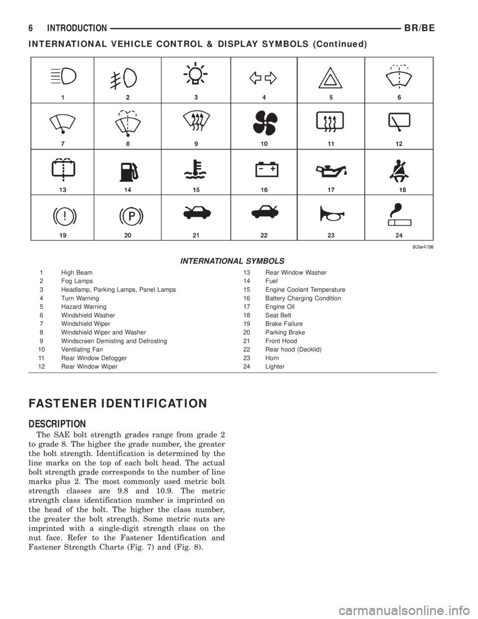
INTERNATIONAL SYMBOLS
1 High Beam 13 Rear Window Washer
2 Fog Lamps 14 Fuel
3 Headlamp, Parking Lamps, Panel Lamps 15 Engine Coolant Temperature
4 Turn Warning 16 Battery Charging Condition
5 Hazard Warning 17 Engine Oil
6 Windshield Washer 18 Seat Belt
7 Windshield Wiper 19 Brake Failure
8 Windshield Wiper and Washer 20 Parking Brake
9 Windscreen Demisting and Defrosting 21 Front Hood
10 Ventilating Fan 22 Rear hood (Decklid)
11 Rear Window Defogger 23 Horn
12 Rear Window Wiper 24 Lighter
6 INTRODUCTIONBR/BE
INTERNATIONAL VEHICLE CONTROL & DISPLAY SYMBOLS (Continued)
Page 106 of 2255
REMOVAL
(1) Raise and support the vehicle.
(2) Position an axle lift under the axle and secure
it to the axle.
(3) Remove the wheels and tires.
(4) Remove RWAL sensor from the differential
housing, if necessary.
(5) Remove brake hose from the axle junction
block.
(6) Disconnect parking brake cables and cable
brackets.
(7) Remove vent hose from the axle shaft tube.
(8) Mark propeller shaft and yoke for installation
alignment reference.
(9) Remove propeller shaft.
(10) Remove shock absorbers from the axle brack-
ets.
(11) Remove spring clamps and spring brackets.
(12) Remove axle from the vehicle.
INSTALLATION
(1) Raise axle with lift and align to the leaf spring
centering bolts.
(2) Install spring clamps and spring brackets.
(3) Install shock absorbers and tighten to specifica-
tions.
(4) Install RWAL sensor to the differential hous-
ing, if necessary.
(5) Install parking brake cables and cable brackets
(6) Install brake hose to the axle junction block.
(7) Install axle vent hose.
(8) Install propeller shaft with reference marks
aligned.
(9) Install wheels and tires assemblies.
(10) Add gear lubricant, if necessary.
(11) Remove lift from the axle and lower the vehi-
cle.
ADJUSTMENTS
Ring and pinion gears are supplied as matched
sets only. The identifying numbers for the ring and
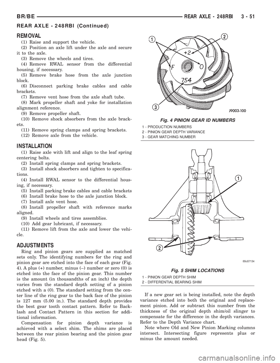
pinion gear are etched into the face of each gear (Fig.
4). A plus (+) number, minus (±) number or zero (0) is
etched into the face of the pinion gear. This number
is the amount (in thousandths of an inch) the depth
varies from the standard depth setting of a pinion
etched with a (0). The standard setting from the cen-
ter line of the ring gear to the back face of the pinion
is 127 mm (5.00 in.). The standard depth provides
the best gear tooth contact pattern. Refer to Back-
lash and Contact Pattern in this section for addi-
tional information.
Compensation for pinion depth variance is
achieved with a select shim. The shims are placed
between the rear pinion bearing and the pinion gear
head (Fig. 5).If a new gear set is being installed, note the depth
variance etched into both the original and replace-
ment pinion. Add or subtract this number from the
thickness of the original depth shim/oil slinger to
compensate for the difference in the depth variances.
Refer to the Depth Variance chart.
Note where Old and New Pinion Marking columns
intersect. Intersecting figure represents plus or
minus the amount needed.
Fig. 4 PINION GEAR ID NUMBERS
1 - PRODUCTION NUMBERS
2 - PINION GEAR DEPTH VARIANCE
3 - GEAR MATCHING NUMBER
Fig. 5 SHIM LOCATIONS
1 - PINION GEAR DEPTH SHIM
2 - DIFFERENTIAL BEARING SHIM
BR/BEREAR AXLE - 248RBI 3 - 51
REAR AXLE - 248RBI (Continued)
Page 262 of 2255
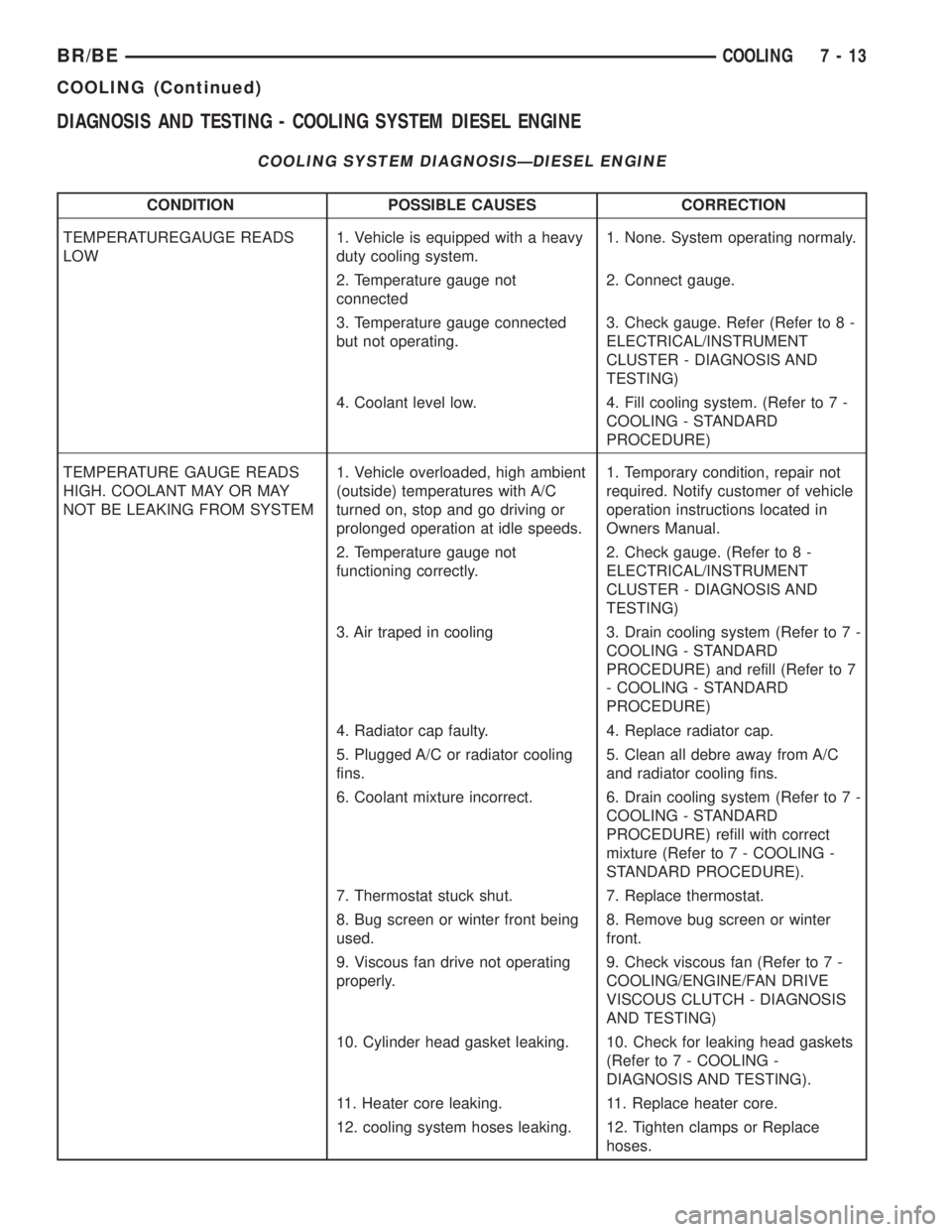
DIAGNOSIS AND TESTING - COOLING SYSTEM DIESEL ENGINE
COOLING SYSTEM DIAGNOSISÐDIESEL ENGINE
CONDITION POSSIBLE CAUSES CORRECTION
TEMPERATUREGAUGE READS
LOW1. Vehicle is equipped with a heavy
duty cooling system.1. None. System operating normaly.
2. Temperature gauge not
connected2. Connect gauge.
3. Temperature gauge connected
but not operating.3. Check gauge. Refer (Refer to 8 -
ELECTRICAL/INSTRUMENT
CLUSTER - DIAGNOSIS AND
TESTING)
4. Coolant level low. 4. Fill cooling system. (Refer to 7 -
COOLING - STANDARD
PROCEDURE)
TEMPERATURE GAUGE READS
HIGH. COOLANT MAY OR MAY
NOT BE LEAKING FROM SYSTEM1. Vehicle overloaded, high ambient
(outside) temperatures with A/C
turned on, stop and go driving or
prolonged operation at idle speeds.1. Temporary condition, repair not
required. Notify customer of vehicle
operation instructions located in
Owners Manual.
2. Temperature gauge not
functioning correctly.2. Check gauge. (Refer to 8 -
ELECTRICAL/INSTRUMENT
CLUSTER - DIAGNOSIS AND
TESTING)
3. Air traped in cooling 3. Drain cooling system (Refer to 7 -
COOLING - STANDARD
PROCEDURE) and refill (Refer to 7
- COOLING - STANDARD
PROCEDURE)
4. Radiator cap faulty. 4. Replace radiator cap.
5. Plugged A/C or radiator cooling
fins.5. Clean all debre away from A/C
and radiator cooling fins.
6. Coolant mixture incorrect. 6. Drain cooling system (Refer to 7 -
COOLING - STANDARD
PROCEDURE) refill with correct
mixture (Refer to 7 - COOLING -
STANDARD PROCEDURE).
7. Thermostat stuck shut. 7. Replace thermostat.
8. Bug screen or winter front being
used.8. Remove bug screen or winter
front.
9. Viscous fan drive not operating
properly.9. Check viscous fan (Refer to 7 -
COOLING/ENGINE/FAN DRIVE
VISCOUS CLUTCH - DIAGNOSIS
AND TESTING)
10. Cylinder head gasket leaking. 10. Check for leaking head gaskets
(Refer to 7 - COOLING -
DIAGNOSIS AND TESTING).
11. Heater core leaking. 11. Replace heater core.
12. cooling system hoses leaking. 12. Tighten clamps or Replace
hoses.
BR/BECOOLING 7 - 13
COOLING (Continued)
Page 303 of 2255
(1) To determine if the thermostat is defective, it
must be removed from the vehicle (Refer to 7 -
COOLING/ENGINE/ENGINE COOLANT THERMO-
STAT - REMOVAL).
(2) After the thermostat has been removed, exam-
ine the thermostat and inside of thermostat housing
for contaminants. If contaminants are found, the
thermostat may already be in a ªstuck openº position.
Flush the cooling system before replacing thermostat
(Refer to 7 - COOLING - STANDARD PROCE-
DURE).
(3) Place the thermostat into a container filled
with water.
(4) Place the container on a hot plate or other suit-
able heating device.
(5) Place a commercially available radiator ther-
mometer into the water.
(6) Apply heat to the water while observing the
thermostat and thermometer.
(7) When the water temperature reaches 83ÉC
(181ÉF) the thermostat should start to open (valve
will start to move). If the valve starts to move before
this temperature is reached, it is opening too early.
Replace thermostat. The thermostat should be fully
open (valve will stop moving) at 95ÉC (203ÉF). If the
valve is still moving when the water temperature
reaches 203É, it is opening too late. Replace thermo-
stat. If the valve refuses to move at any time, replace
thermostat.
REMOVAL
WARNING: DO NOT LOOSEN THE RADIATOR
DRAINCOCK WITH THE SYSTEM HOT AND PRES-
SURIZED. SERIOUS BURNS FROM THE COOLANT
CAN OCCUR.
Do not waste reusable coolant. If the solution is
clean, drain the coolant into a clean container for
reuse.
(1) Disconnect the battery negative cables.
(2) Drain cooling system until coolant level is
below thermostat (Refer to 7 - COOLING - STAN-
DARD PROCEDURE).
WARNING: CONSTANT TENSION HOSE CLAMPS
ARE USED ON MOST COOLING SYSTEM HOSES.
WHEN REMOVING OR INSTALLING, USE ONLY
TOOLS DESIGNED FOR SERVICING THIS TYPE OF
CLAMP, SUCH AS SPECIAL CLAMP TOOL (NUMBER
6094). SNAP-ON CLAMP TOOL (NUMBER HPC-20)
MAY BE USED FOR LARGER CLAMPS. ALWAYS
WEAR SAFETY GLASSES WHEN SERVICING CON-
STANT TENSION CLAMPS.CAUTION: A number or letter is stamped into the
tongue of constant tension clamps. If replacement
is necessary, use only an original equipment clamp
with a matching number or letter.
(3) Remove radiator hose clamp and hose from
thermostat housing.
(4) Remove the three (3) water outlet-to-cylinder
head bolts and remove the water outlet connector
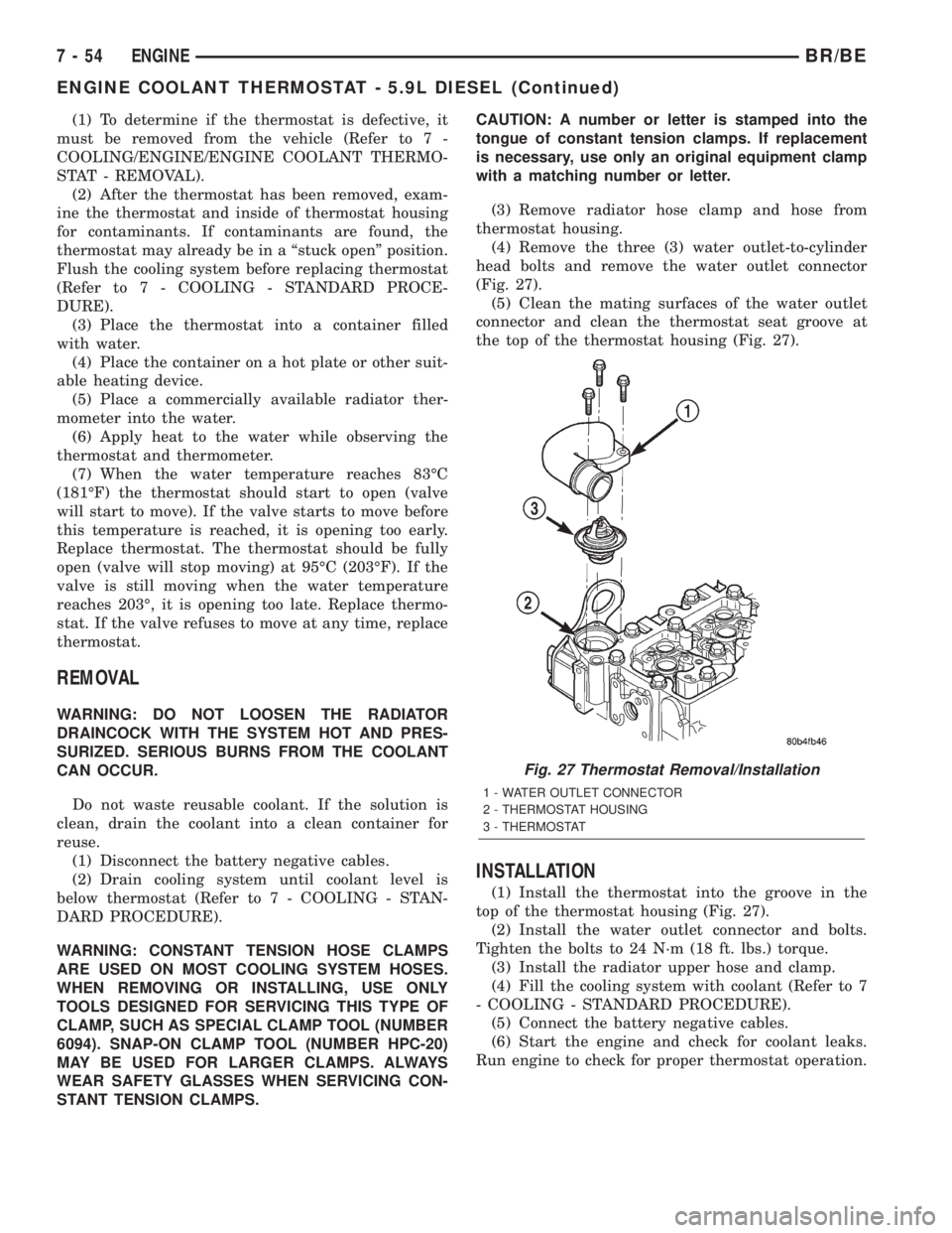
(Fig. 27).
(5) Clean the mating surfaces of the water outlet
connector and clean the thermostat seat groove at
the top of the thermostat housing (Fig. 27).
INSTALLATION
(1) Install the thermostat into the groove in the
top of the thermostat housing (Fig. 27).
(2) Install the water outlet connector and bolts.
Tighten the bolts to 24 N´m (18 ft. lbs.) torque.
(3) Install the radiator upper hose and clamp.
(4) Fill the cooling system with coolant (Refer to 7
- COOLING - STANDARD PROCEDURE).
(5) Connect the battery negative cables.
(6) Start the engine and check for coolant leaks.
Run engine to check for proper thermostat operation.
Fig. 27 Thermostat Removal/Installation
1 - WATER OUTLET CONNECTOR
2 - THERMOSTAT HOUSING
3 - THERMOSTAT
7 - 54 ENGINEBR/BE
ENGINE COOLANT THERMOSTAT - 5.9L DIESEL (Continued)
Page 360 of 2255
CHIME/BUZZER
TABLE OF CONTENTS
page page
CHIME WARNING SYSTEM
DESCRIPTION..........................1
OPERATION............................1DIAGNOSIS AND TESTING - CHIME
WARNING SYSTEM.....................2
CHIME WARNING SYSTEM
DESCRIPTION
A chime warning system is standard factory-in-
stalled equipment on this model. The chime warning
system uses a single chime tone generator that is
integral to the Central Timer Module (CTM) to pro-
vide an audible indication of various vehicle condi-
tions that may require the attention of the vehicle
operator. The chime warning system includes the fol-
lowing major components, which are described in fur-
ther detail elsewhere in this service manual:
²Central Timer Module- The Central Timer
Module (CTM) is located under the driver side end of
the instrument panel, inboard of the instrument
panel steering column opening. The CTM contains an
integral chime tone generator to provide all of the
proper chime warning system features based upon
the monitored inputs.
²Door Ajar Switch- A door ajar switch is inte-
gral to the driver side front door latch. This switch
provides an input to the chime warning system indi-
cating whether the driver side front door is open or
closed.
²Headlamp Switch- The headlamp switch is
located on the instrument panel outboard of the
steering column. The headlamp switch provides an
input to the chime warning system indicating when
the exterior lamps are turned On or Off.
²Ignition Switch- A key-in ignition switch is
integral to the ignition switch. The key-in ignition
switch provides an input to the chime warning sys-
tem indicating whether a key is present in the igni-
tion lock cylinder.
²Seat Belt Switch- A seat belt switch is inte-
gral to the driver side front seat belt buckle unit. The
seat belt switch provides an input to the chime warn-
ing system indicating whether the driver side front
seat belt is fastened.
Hard wired circuitry connects many of the chime
warning system components to each other through
the electrical system of the vehicle. These hard wired
circuits are integral to several wire harnesses, which
are routed throughout the vehicle and retained bymany different methods. These circuits may be con-
nected to each other, to the vehicle electrical system
and to the chime warning system components
through the use of a combination of soldered splices,
splice block connectors, and many different types of
wire harness terminal connectors and insulators.
Refer to the appropriate wiring information. The wir-
ing information includes wiring diagrams, proper
wire and connector repair procedures, further details
on wire harness routing and retention, as well as
pin-out and location views for the various wire har-
ness connectors, splices and grounds.
The CTM chime warning system circuitry and the
integral chime tone generator cannot be adjusted or
repaired. If the CTM or the chime tone generator are
damaged or faulty, the CTM unit must be replaced.
OPERATION
The chime warning system is designed to provide an
audible output as an indication of various conditions
that may require the attention or awareness of the
vehicle operator. The chime warning system compo-
nents operate on battery current received through a
fused B(+) fuse in the Junction Block (JB) on a non-
switched fused B(+) circuit so that the system may
operate regardless of the ignition switch position.
The chime warning system provides an audible
indication to the vehicle operator under the following
conditions:
²Fasten Seat Belt Warning- The Central
Timer Module (CTM) chime tone generator will gen-
erate repetitive chime tones at a slow rate to
announce that a hard wired input from the seat belt
switch to the Electro-Mechanical Instrument Cluster
(EMIC) indicates that the driver side front seat belt
is not fastened with the ignition switch in the On
position. Unless the driver side front seat belt is fas-
tened, the chimes will continue to sound for a dura-
tion of about seven seconds each time the ignition
switch is turned to the On position or until the driver
side front seat belt is fastened, whichever occurs
first. This chime tone is based upon a hard wired
chime request input to the CTM from the EMIC, but
is not related to the operation of the EMIC ªSeatbeltº
indicator.
BR/BECHIME/BUZZER 8B - 1
Page 361 of 2255
²Head/Park Lights-On Warning- The CTM
chime tone generator will generate repetitive chime
tones at a fast rate to announce that hard wired
inputs from the driver door ajar switch, headlamp
switch, and ignition switch indicate that the exterior
lamps are turned On with the driver side front door
opened and the ignition switch in the Off position.
The chimes will continue to sound until the exterior
lamps are turned Off, the driver side front door is
closed, or the ignition switch is turned to the On
position, whichever occurs first.
²Key-In-Ignition Warning- The CTM chime
tone generator will generate repetitive chime tones at
a fast rate to announce that hard wired inputs from
the driver door ajar switch, headlamp switch, and
ignition switch indicate that the key is in the ignition
lock cylinder with the driver side front door opened
and the ignition switch in the Off position. The
chimes will continue to sound until the key is
removed from the ignition lock cylinder, the driver
side front door is closed, or the ignition switch is
turned to the On position, whichever occurs first.
²Warning Chime Support- The CTM chime
tone generator will generate repetitive chime tones at
a slow rate to announce that a hard wired chime
request input has been received from the EMIC.
These chime tones provide an audible alert to the
vehicle operator that supplements certain visual indi-
cations displayed by the EMIC. Supplemented indica-
tions include the following:
²The ªAirbagº indicator is illuminated. The
chimes will continue to sound for a duration of about
four seconds each time the indicator is illuminated or
until the ignition switch is turned to the Off position,
whichever occurs first.
²The ªCheck Gagesº indicator is illuminated. The
chimes will continue to sound for a duration of about
two seconds each time the indicator is illuminated or
until the ignition switch is turned to the Off position,
whichever occurs first.
²The ªLow Fuelº indicator is illuminated. The
chimes will continue to sound for a duration of about
two seconds each time the indicator is illuminated or
until the ignition switch is turned to the Off position,
whichever occurs first.
²The ªLow Washº indicator is illuminated. The
chimes will continue to sound for a duration of about
two seconds each time the indicator is illuminated or
until the ignition switch is turned to the Off position,
whichever occurs first.
²The ªTrans Tempº indicator is illuminated (auto-
matic transmission only). The chimes will continue to
sound for a duration of about two seconds each time
the indicator is illuminated or until the ignition
switch is turned to the Off position, whichever occurs
first.²The vehicle is over a programmed speed value
(Middle East Gulf Coast Country (GCC) only). The
CTM chime tone generator will generate repetitive
chime tones at a slow rate to announce that the vehi-
cle speed exceeds a programmed value. The chimes
will continue to sound until the vehicle speed is
below the programmed value.
²The ªWater-In-Fuelº indicator is illuminated
(diesel engine only). The chimes will continue to
sound for a duration of about two seconds each time
the indicator is illuminated or until the ignition
switch is turned to the Off position, whichever occurs
first.
The CTM provides chime service for all available
features in the chime warning system. The CTM
relies upon hard wired inputs from the driver door
ajar switch, the EMIC, the headlamp switch, and the
key-in ignition switch (ignition switch) to provide
chime service for all of the chime warning system
features. Upon receiving the proper inputs, the CTM
activates the integral chime tone generator to pro-
vide the audible chime tone to the vehicle operator.
The chime tone generator in the CTM is capable of
producing repeated chime tones at two different
rates, slow or fast. The slow chime rate is about fifty
chime tones per minute, while the fast chime rate is
about 180 chime tones per minute. The internal pro-
gramming of the CTM and the EMIC determines the
priority of each chime tone request input that is
received, as well as the rate and duration of each
chime tone that is to be generated.
The hard wired chime warning system inputs to
the CTM and the EMIC, as well as other hard wired
circuits for this system may be diagnosed and tested
using conventional diagnostic tools and procedures.
See the owner's manual in the vehicle glove box for
more information on the features provided by the
chime warning system.
DIAGNOSIS AND TESTING - CHIME WARNING
SYSTEM
Refer to the appropriate wiring information. The
wiring information includes wiring diagrams, proper
wire and connector repair procedures, further details
on wire harness routing and retention, as well as
pin-out and location views for the various wire har-
ness connectors, splices and grounds. The hard wired
chime warning system inputs to the Central Timer
Module (CTM) and the Electro-Mechanical Instru-
ment Cluster (EMIC), as well as other hard wired
circuits for this system may be diagnosed and tested
using conventional diagnostic tools and procedures.
8B - 2 CHIME/BUZZERBR/BE
CHIME WARNING SYSTEM (Continued)
Page 363 of 2255
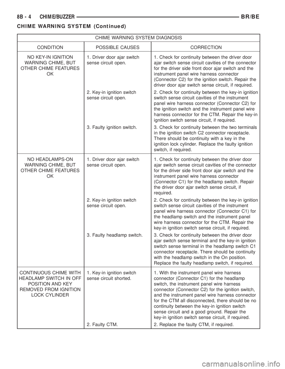
CHIME WARNING SYSTEM DIAGNOSIS
CONDITION POSSIBLE CAUSES CORRECTION
NO KEY-IN IGNITION
WARNING CHIME, BUT
OTHER CHIME FEATURES
OK1. Driver door ajar switch
sense circuit open.1. Check for continuity between the driver door
ajar switch sense circuit cavities of the connector
for the driver side front door ajar switch and the
instrument panel wire harness connector
(Connector C2) for the ignition switch. Repair the
driver door ajar switch sense circuit, if required.
2. Key-in ignition switch
sense circuit open.2. Check for continuity between the key-in ignition
switch sense circuit cavities of the instrument
panel wire harness connector (Connector C2) for
the ignition switch and the instrument panel wire
harness connector for the CTM. Repair the key-in
ignition switch sense circuit, if required.
3. Faulty ignition switch. 3. Check for continuity between the two terminals
in the ignition switch C2 connector receptacle.
There should be continuity with a key in the
ignition lock cylinder. Replace the faulty ignition
switch, if required.
NO HEADLAMPS-ON
WARNING CHIME, BUT
OTHER CHIME FEATURES
OK1. Driver door ajar switch
sense circuit open.1. Check for continuity between the driver door
ajar switch sense circuit cavities of the connector
for the driver side front door ajar switch and the
instrument panel wire harness connector
(Connector C1) for the headlamp switch. Repair
the driver door ajar switch sense circuit, if
required.
2. Key-in ignition switch
sense circuit open.2. Check for continuity between the key-in ignition
switch sense circuit cavities of the instrument
panel wire harness connector (Connector C1) for
the headlamp switch and the instrument panel
wire harness connector for the CTM. Repair the
key-in ignition switch sense circuit, if required.
3. Faulty headlamp switch. 3. Check for continuity between the driver door
ajar switch sense terminal and the key-in ignition
switch sense terminal in the headlamp switch C1
connector receptacle. There should be continuity
with the headlamp switch in the On position.
Replace the faulty headlamp switch, if required.
CONTINUOUS CHIME WITH
HEADLAMP SWITCH IN OFF
POSITION AND KEY
REMOVED FROM IGNITION
LOCK CYLINDER1. Key-in ignition switch
sense circuit shorted.1. With the instrument panel wire harness
connector (Connector C1) for the headlamp
switch, the instrument panel wire harness
connector (Connector C2) for the ignition switch,
and the instrument panel wire harness connector
for the CTM all disconnected, there should be no
continuity between the key-in ignition switch
sense circuit and a good ground. Repair the
key-in ignition switch sense circuit, if required.
2. Faulty CTM. 2. Replace the faulty CTM, if required.
8B - 4 CHIME/BUZZERBR/BE
CHIME WARNING SYSTEM (Continued)
Page 401 of 2255
Test the specific gravity of the electrolyte in each
battery cell. If the specific gravity of all cells is above
1.235, but the variation between cells is more than
fifty points (0.050), the battery should be replaced. If
the specific gravity of one or more cells is less than
1.235, charge the battery at a rate of approximately
five amperes. Continue charging the battery until
three consecutive specific gravity tests, taken at one-
hour intervals, are constant. If the cell specific grav-
ity variation is more than fifty points (0.050) at the
end of the charge period, replace the battery.
When the specific gravity of all cells is above 1.235,
and the cell variation is less than fifty points (0.050),
the battery may be load tested to determine its
cranking capacity. Refer to Standard Procedures for
the proper battery load test procedures.
STANDARD PROCEDURE - OPEN-CIRCUIT
VOLTAGE TEST
A battery open-circuit voltage (no load) test will
show the approximate state-of-charge of a battery.
This test can be used in place of the hydrometer test
when a hydrometer is not available, or for mainte-
nance-free batteries with non-removable cell caps.
Before proceeding with this test, completely charge
the battery (Refer to 8 - ELECTRICAL/BATTERY
SYSTEM/BATTERY - STANDARD PROCEDURE).
(1) Before measuring the open-circuit voltage, the
surface charge must be removed from the battery.
Turn on the headlamps for fifteen seconds, then
allow up to five minutes for the battery voltage to
stabilize.
(2) Disconnect and isolate both battery cables, neg-
ative cable first.
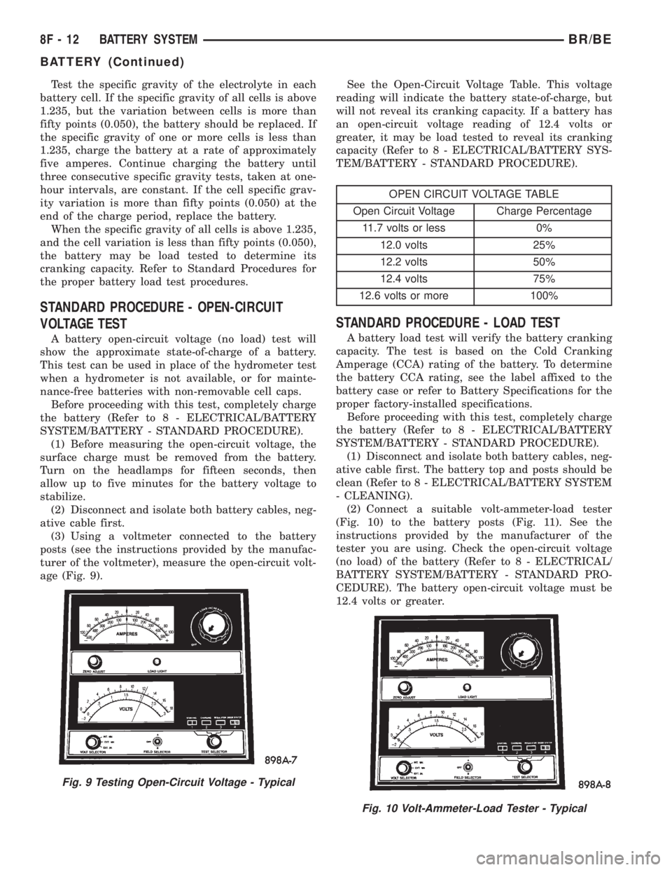
(3) Using a voltmeter connected to the battery
posts (see the instructions provided by the manufac-
turer of the voltmeter), measure the open-circuit volt-
age (Fig. 9).See the Open-Circuit Voltage Table. This voltage
reading will indicate the battery state-of-charge, but
will not reveal its cranking capacity. If a battery has
an open-circuit voltage reading of 12.4 volts or
greater, it may be load tested to reveal its cranking
capacity (Refer to 8 - ELECTRICAL/BATTERY SYS-
TEM/BATTERY - STANDARD PROCEDURE).
OPEN CIRCUIT VOLTAGE TABLE
Open Circuit Voltage Charge Percentage
11.7 volts or less 0%
12.0 volts 25%
12.2 volts 50%
12.4 volts 75%
12.6 volts or more 100%
STANDARD PROCEDURE - LOAD TEST
A battery load test will verify the battery cranking
capacity. The test is based on the Cold Cranking
Amperage (CCA) rating of the battery. To determine
the battery CCA rating, see the label affixed to the
battery case or refer to Battery Specifications for the
proper factory-installed specifications.
Before proceeding with this test, completely charge
the battery (Refer to 8 - ELECTRICAL/BATTERY
SYSTEM/BATTERY - STANDARD PROCEDURE).
(1) Disconnect and isolate both battery cables, neg-
ative cable first. The battery top and posts should be
clean (Refer to 8 - ELECTRICAL/BATTERY SYSTEM
- CLEANING).
(2) Connect a suitable volt-ammeter-load tester
(Fig. 10) to the battery posts (Fig. 11). See the
instructions provided by the manufacturer of the
tester you are using. Check the open-circuit voltage
(no load) of the battery (Refer to 8 - ELECTRICAL/
BATTERY SYSTEM/BATTERY - STANDARD PRO-
CEDURE). The battery open-circuit voltage must be
12.4 volts or greater.
Fig. 9 Testing Open-Circuit Voltage - Typical
Fig. 10 Volt-Ammeter-Load Tester - Typical
8F - 12 BATTERY SYSTEMBR/BE
BATTERY (Continued)
Page 407 of 2255
(5) Remove the battery hold down strap from the
top of the battery case.
INSTALLATION
(1) Clean and inspect the battery hold down hard-
ware (Refer to 8 - ELECTRICAL/BATTERY SYSTEM
- CLEANING).
(2) Position the battery hold down strap across the
top of the battery case.
(3) Install and tighten the two battery hold down
bolts through the holes on each end of the hold down
strap and into the U-nuts on each side of the battery
tray. Tighten the bolts to 4 N´m (35 in. lbs.).
(4) Reconnect the battery negative cable terminal
clamp to the battery negative terminal post. Tighten
the terminal clamp pinch-bolt hex nut to 4 N´m (35
in. lbs.).
BATTERY CABLE
DESCRIPTION
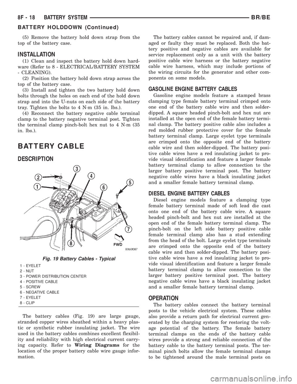
The battery cables (Fig. 19) are large gauge,
stranded copper wires sheathed within a heavy plas-
tic or synthetic rubber insulating jacket. The wire
used in the battery cables combines excellent flexibil-
ity and reliability with high electrical current carry-
ing capacity. Refer toWiring Diagramsfor the
location of the proper battery cable wire gauge infor-
mation.The battery cables cannot be repaired and, if dam-
aged or faulty they must be replaced. Both the bat-
tery positive and negative cables are available for
service replacement only as a unit with the battery
positive cable wire harness or the battery negative
cable wire harness, which may include portions of
the wiring circuits for the generator and other com-
ponents on some models.
GASOLINE ENGINE BATTERY CABLES
Gasoline engine models feature a stamped brass
clamping type female battery terminal crimped onto
one end of the battery cable wire and then solder-
dipped. A square headed pinch-bolt and hex nut are
installed at the open end of the female battery termi-
nal clamp. The battery positive cable also includes a
red molded rubber protective cover for the female
battery terminal clamp. Large eyelet type terminals
are crimped onto the opposite end of the battery
cable wire and then solder-dipped. The battery posi-
tive cable wires have a red insulating jacket to pro-
vide visual identification and feature a larger female
battery terminal clamp to allow connection to the
larger battery positive terminal post. The battery
negative cable wires have a black insulating jacket
and a smaller female battery terminal clamp.
DIESEL ENGINE BATTERY CABLES
Diesel engine models feature a clamping type
female battery terminal made of soft lead die cast
onto one end of the battery cable wire. A square
headed pinch-bolt and hex nut are installed at the
open end of the female battery terminal clamp. The
pinch-bolt on the left side battery positive cable
female terminal clamp also has a stud extending
from the head of the bolt. Large eyelet type terminals
are crimped onto the opposite end of the battery
cable wire and then solder-dipped. The battery posi-
tive cable wires have a red insulating jacket to pro-
vide visual identification and feature a larger female
battery terminal clamp to allow connection to the
larger battery positive terminal post. The battery
negative cable wires have a black insulating jacket
and a smaller female battery terminal clamp.
OPERATION
The battery cables connect the battery terminal
posts to the vehicle electrical system. These cables
also provide a return path for electrical current gen-
erated by the charging system for restoring the volt-
age potential of the battery. The female battery
terminal clamps on the ends of the battery cable
wires provide a strong and reliable connection of the
battery cable to the battery terminal posts. The ter-
minal pinch bolts allow the female terminal clamps
to be tightened around the male terminal posts on
Fig. 19 Battery Cables - Typical
1 - EYELET
2 - NUT
3 - POWER DISTRIBUTION CENTER
4 - POSITIVE CABLE
5 - SCREW
6 - NEGATIVE CABLE
7 - EYELET
8 - CLIP
8F - 18 BATTERY SYSTEMBR/BE
BATTERY HOLDDOWN (Continued)
Page 408 of 2255
the top of the battery. The eyelet terminals secured
to the ends of the battery cable wires opposite the
female battery terminal clamps provide secure and
reliable connection of the battery to the vehicle elec-
trical system.
GASOLINE ENGINE
The battery positive cable terminal clamp is
crimped onto the ends of two wires. One wire has an
eyelet terminal that connects the battery positive
cable to the B(+) terminal stud of the Power Distri-
bution Center (PDC), and the other wire has an eye-
let terminal that connects the battery positive cable
to the B(+) terminal stud of the engine starter motor
solenoid. The battery negative cable terminal clamp
is also crimped onto the ends of two wires. One wire
has an eyelet terminal that connects the battery neg-
ative cable to the vehicle powertrain through a stud
on the front of the left engine cylinder head. The
other wire has an eyelet terminal that connects the
battery negative cable to the vehicle body through a
ground screw on the left front fender inner shield,
just ahead of the battery. An additional ground wire
with two eyelet terminals is used to provide ground
to the vehicle frame. One eyelet terminal of this
ground wire is installed under the head of the bat-
tery negative cable terminal clamp pinch-bolt, and
the other eyelet terminal is secured with a ground
screw to the outer surface of the left frame rail,
below the battery.
DIESEL ENGINE
The left battery positive cable terminal clamp is
die cast onto the ends of two wires. One wire has an
eyelet terminal that connects the left battery positive
cable to the B(+) terminal stud of the Power Distri-
bution Center (PDC), and the other wire has an eye-
let terminal that connects the left battery positive
cable to the B(+) terminal stud of the engine starter
motor solenoid. The right battery positive cable ter-
minal clamp is die cast onto the end of a single wire.
The eyelet terminal on the other end of the right bat-
tery positive cable is connected to the stud on the
pinch-bolt of the left battery positive cable terminal
clamp. This stud also provides a connection point for
the eyelet terminals from the fuel heater relay and
intake air heater relay jumper harness take outs. All
of these eyelet terminals are secured to the left bat-
tery positive cable terminal clamp pinch-bolt stud
with a single hex nut.The left battery negative cable terminal clamp is
die cast onto the ends of two wires. One wire has an
eyelet terminal that connects the left battery nega-
tive cable to the vehicle powertrain through a ground
screw on the left side of the engine block, below the
power steering and vacuum pumps. The other wire
has an eyelet terminal that connects the left battery
negative cable to the vehicle body through a ground
screw on the left front fender inner shield, just ahead
of the left battery. An additional ground wire with
two eyelet terminals is used to provide ground to the
vehicle frame. One eyelet terminal of this ground
wire is installed under the nut of the left battery
negative cable terminal clamp pinch-bolt, and the
other eyelet terminal is secured with a ground screw
to the outer surface of the left frame rail, below the
left battery. The right battery negative cable terminal
is also die cast onto the ends of two wires. One wire
has an eyelet terminal that connects the right bat-
tery negative cable to the vehicle powertrain through
a ground screw on the right side of the engine block,
just forward of the right engine mount. The other
wire has an eyelet terminal that connects the right
battery negative cable to the vehicle body through a
ground screw on the right front fender inner shield,
just behind the right battery.
DIAGNOSIS AND TESTING - BATTERY CABLES
A voltage drop test will determine if there is exces-
sive resistance in the battery cable terminal connec-
tions or the battery cables. If excessive resistance is
found in the battery cable connections, the connec-
tion point should be disassembled, cleaned of all cor-
rosion or foreign material, then reassembled.
Following reassembly, check the voltage drop for the
battery cable connection and the battery cable again
to confirm repair.
When performing the voltage drop test, it is impor-
tant to remember that the voltage drop is giving an
indication of the resistance between the two points at
which the voltmeter probes are attached.EXAM-
PLE:When testing the resistance of the battery pos-
itive cable, touch the voltmeter leads to the battery
positive cable terminal clamp and to the battery pos-
itive cable eyelet terminal at the starter solenoid
B(+) terminal stud. If you probe the battery positive
terminal post and the battery positive cable eyelet
terminal at the starter solenoid B(+) terminal stud,
you are reading the combined voltage drop in the
battery positive cable terminal clamp-to-terminal
post connection and the battery positive cable.
BR/BEBATTERY SYSTEM 8F - 19
BATTERY CABLE (Continued)