power distribution center DODGE RAM 2002 Service Repair Manual
[x] Cancel search | Manufacturer: DODGE, Model Year: 2002, Model line: RAM, Model: DODGE RAM 2002Pages: 2255, PDF Size: 62.07 MB
Page 293 of 2255
INSTALLATION
(1) Install fan blade assembly to viscous fan drive.
Tighten mounting bolts to 23 N´m (17 ft. lbs.) torque.
(2) Position the fan shroud and fan blade/viscous
fan drive to the vehicle as an assembly.
(3) Install viscous fan drive assembly on fan hub
shaft (Fig. 7). Tighten mounting nut to 57 N´m (42 ft.
lbs.) torque.
(4) Install fan shroud bolts into position and
tighten the mounting bolts to 6 N´m (50 in. lbs.)
torque.
(5) Connect the battery negative cables.
NOTE:
Viscous Fan Drive Fluid Pump Out Requirement:
After installing a new viscous fan drive, bring the
engine speed up to approximately 2000 rpm and
hold for approximately two minutes. This will
ensure proper fluid distribution within the drive.
ENGINE BLOCK HEATER - 5.9L
DESCRIPTION
WARNING: DO NOT OPERATE ENGINE UNLESS
BLOCK HEATER CORD HAS BEEN DISCONNECTED
FROM POWER SOURCE AND SECURED IN PLACE.
THE POWER CORD MUST BE SECURED IN ITS
RETAINING CLIPS AND ROUTED AWAY FROM
EXHAUST MANIFOLDS AND MOVING PARTS.
An optional engine block heater is available on all
models. The heater is equipped with a power cord.
The heater is mounted in a core hole of the engine
cylinder block (in place of a freeze plug) with the
heating element immersed in engine coolant. The
cord is attached to an engine compartment compo-
nent with tie-straps.
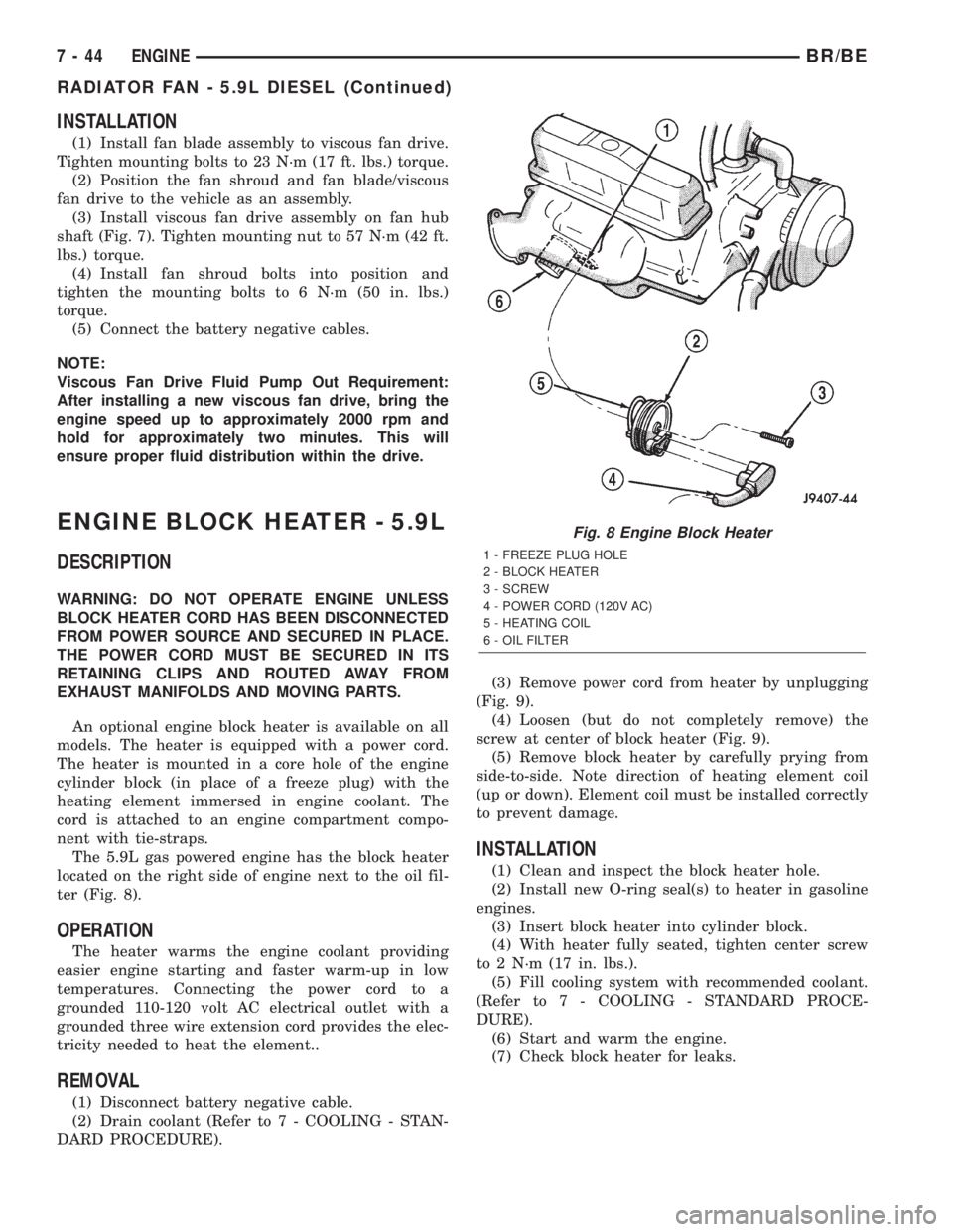
The 5.9L gas powered engine has the block heater
located on the right side of engine next to the oil fil-
ter (Fig. 8).
OPERATION
The heater warms the engine coolant providing
easier engine starting and faster warm-up in low
temperatures. Connecting the power cord to a
grounded 110-120 volt AC electrical outlet with a
grounded three wire extension cord provides the elec-
tricity needed to heat the element..
REMOVAL
(1) Disconnect battery negative cable.
(2) Drain coolant (Refer to 7 - COOLING - STAN-
DARD PROCEDURE).(3) Remove power cord from heater by unplugging
(Fig. 9).
(4) Loosen (but do not completely remove) the
screw at center of block heater (Fig. 9).
(5) Remove block heater by carefully prying from
side-to-side. Note direction of heating element coil
(up or down). Element coil must be installed correctly
to prevent damage.
INSTALLATION
(1) Clean and inspect the block heater hole.
(2) Install new O-ring seal(s) to heater in gasoline
engines.
(3) Insert block heater into cylinder block.
(4) With heater fully seated, tighten center screw
to 2 N´m (17 in. lbs.).
(5) Fill cooling system with recommended coolant.
(Refer to 7 - COOLING - STANDARD PROCE-
DURE).
(6) Start and warm the engine.
(7) Check block heater for leaks.
Fig. 8 Engine Block Heater
1 - FREEZE PLUG HOLE
2 - BLOCK HEATER
3 - SCREW
4 - POWER CORD (120V AC)
5 - HEATING COIL
6 - OIL FILTER
7 - 44 ENGINEBR/BE
RADIATOR FAN - 5.9L DIESEL (Continued)
Page 369 of 2255
HARD WIRED OUTPUTS
The hard wired outputs of the CTM include the fol-
lowing:
²CCD bus± - high-line/premium version only
²CCD bus+ - high-line/premium version only
²Courtesy lamp switch output - high-line/pre-
mium version only
²Door lock driver - high-line/premium version
only
²Door unlock driver - high-line/premium version
only
²Headlamp relay control - high-line/premium ver-
sion only
²Heated seat relay control - premium version
only
²Horn relay control - high-line/premium version
only
²VTSS indicator driver - high-line/premium ver-
sion only
²Wiper motor relay control
MESSAGING
The high-line/premium CTM uses the following
messages received from other electronic modules over
the CCD data bus:
²Airbag Deploy (ACM)
²Charging System Failure (PCM)
²Engine RPM (PCM)
²System Voltage (PCM)
²Vehicle Speed (PCM)
²Voltage Fault (PCM)
The high-line/premium CTM provides the following
messages to other electronic modules over the CCD
data bus:
²Engine Enable (PCM)
²Radio Seek Up (Radio)
²Radio Seek Down (Radio)
²Radio Volume Up (Radio)
²Radio Volume Down (Radio)
²Preset Scan (Radio)
DIAGNOSIS AND TESTING - CENTRAL TIMER
MODULE
The hard wired inputs to and outputs from the
Central Timer Module (CTM) may be diagnosed and
tested using conventional diagnostic tools and meth-
ods. Refer to the appropriate wiring information. The
wiring information includes wiring diagrams, proper
wire and connector repair procedures, further details
on wire harness routing and retention, as well as
pin-out and location views for the various wire har-
ness connectors, splices and grounds.
However, conventional diagnostic methods may not
prove conclusive in the diagnosis of the high-line/pre-
mium CTM. In order to obtain conclusive testing of
the high-line/premium CTM, the Chrysler CollisionDetection (CCD) data bus network and all of the elec-
tronic modules that provide inputs to or receive out-
puts from the CTM must also be checked. The most
reliable, efficient, and accurate means to diagnose
the high-line/premium CTM, the CCD data bus net-
work, and the electronic modules that provide inputs
to or receive outputs from the high-line/premium
CTM requires the use of a DRBIIItscan tool and the
appropriate diagnostic information. The DRBIIIt
scan tool can provide confirmation that the CCD data
bus network is functional, that all of the electronic
modules are sending and receiving the proper mes-
sages over the CCD data bus, and that the CTM is
receiving the proper hard wired inputs and respond-
ing with the proper hard wired outputs needed to
perform its many functions.
WARNING: ON VEHICLES EQUIPPED WITH AIR-
BAGS, DISABLE THE AIRBAG SYSTEM BEFORE
ATTEMPTING ANY STEERING WHEEL, STEERING
COLUMN, OR INSTRUMENT PANEL COMPONENT
DIAGNOSIS OR SERVICE. DISCONNECT AND ISO-
LATE THE BATTERY NEGATIVE (GROUND) CABLE,
THEN WAIT TWO MINUTES FOR THE AIRBAG SYS-
TEM CAPACITOR TO DISCHARGE BEFORE PER-
FORMING FURTHER DIAGNOSIS OR SERVICE. THIS
IS THE ONLY SURE WAY TO DISABLE THE AIRBAG
SYSTEM. FAILURE TO TAKE THE PROPER PRE-
CAUTIONS COULD RESULT IN ACCIDENTAL AIR-
BAG DEPLOYMENT AND POSSIBLE PERSONAL
INJURY.
NOTE: The following tests may not prove conclu-
sive in the diagnosis of the high-line or premium
versions of the Central Timer Module (CTM). The
most reliable, efficient, and accurate means to diag-
nose the high-line or premium CTM requires the
use of a DRBIIITscan tool and the appropriate diag-
nostic information.
(1) Check the fused B(+) fuse (Fuse 13 - 10
ampere) in the Junction Block (JB). If OK, go to Step
2. If not OK, repair the shorted circuit or component
as required and replace the faulty fuse.
(2) Check for battery voltage at the fused B(+) fuse
(Fuse 13 - 10 ampere) in the JB. If OK, go to Step 3.
If not OK, repair the open fused B(+) circuit between
the JB and the Power Distribution Center (PDC) as
required.
(3) For a base version CTM, check the fused igni-
tion switch output (st-run) fuse (Fuse 11 - 10 ampere)
in the JB. For a high-line/premium version CTM,
check the fused ignition switch output (run-acc) fuse
(Fuse6-25ampere) in the JB. If OK, go to Step 4. If
not OK, repair the shorted circuit or component as
required and replace the faulty fuse.
8E - 4 ELECTRONIC CONTROL MODULESBR/BE
CENTRAL TIMER MODULE (Continued)
Page 388 of 2255
(5) Back-probe the heated seat module wire har-
ness connector (Fig. 20) , do not disconnect. Check
cavity #2 for approx. 5v, 5 voltage should be present,
If OK go to Step 6. If NOT OK replace the heated
seat control module.
(6) Back-probe the heated seat module wire har-
ness connector, do not disconnect. Check cavity #8 for
a range in voltage from 1.72v (warm seat) ± 3.0v
(cold seat). It should be within this range, If OK
replace the heated seat control module. If NOT OK,
test the Heated Seat Sensor. If NOT OK, replace the
left heated seat element and sensor assembly. If the
heated seat sensor tests OK, check for continuity
between the left heated seat cushion connector and
control module connector on the 5v supply circuit, If
NOT OK, repair the open or shorted 5v supply circuit
as required. If OK check for continuity between the
left heated seat cushion connector and control mod-
ule connector on the temperature sensor input cir-
cuit. If NOT OK, repair the open or shorted
temperature sensor input circuit as required. If OK
replace the heated seat control module.
BOTH SEATS INOPERATIVE
If both seats (driver and passenger) fail to heat
and the indicator lamps on the heated seat switches
for both seats fail to operate, test the heated seat
relay and/or fuses. Refer toRelay Diagnosis and
Testingin the Power Distribution section for heated
seat relay diagnosis and testing procedures. If the
heated seat relay checks OK, go to Step 1.
(1) Back-probe the heated seat module wire har-
ness connector (Fig. 20) , do not disconnect. Check for
continuity between the ground circuit cavity #13 of
the heated seat module connector and a good ground.
If OK go to Step 2. If NOT OK, repair the open or
shorted ground circuit as required.
(2) Back-probe the heated seat module wire har-
ness connector (Fig. 20) , do not disconnect. Check
cavity #4 and #6 for battery voltage, voltage should
be present, If OK go to Step 3. If NOT OK repair the
open or shorted fused B(+) circuit as required.
(3) Back-probe the heated seat module wire har-
ness connector, do not disconnect. Check cavity #2 for
approx. 5v, voltage should be present, replace the
heated seat control module with a known good mod-
ule and verify system operation.
REMOVAL
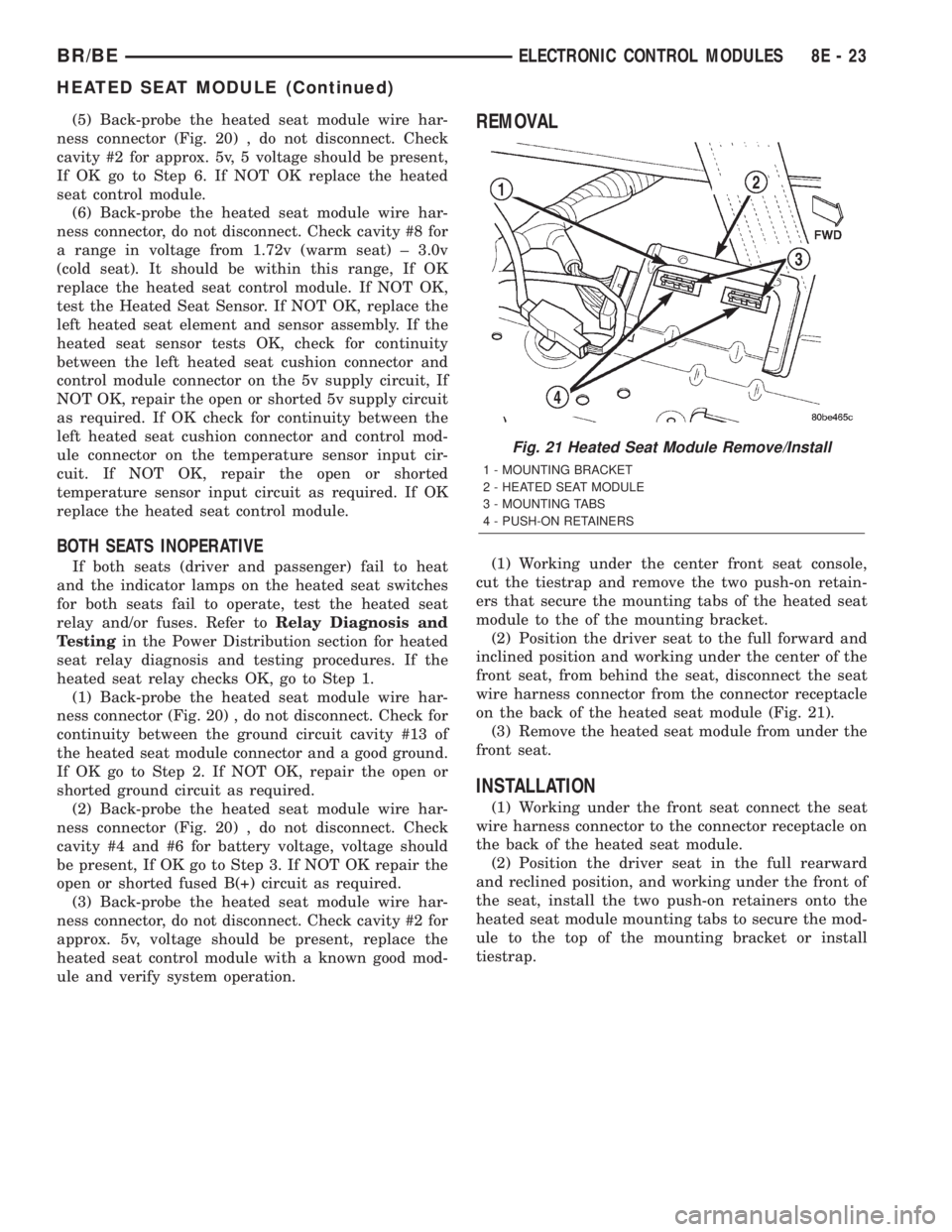
(1) Working under the center front seat console,
cut the tiestrap and remove the two push-on retain-
ers that secure the mounting tabs of the heated seat
module to the of the mounting bracket.
(2) Position the driver seat to the full forward and
inclined position and working under the center of the
front seat, from behind the seat, disconnect the seat
wire harness connector from the connector receptacle
on the back of the heated seat module (Fig. 21).
(3) Remove the heated seat module from under the
front seat.
INSTALLATION
(1) Working under the front seat connect the seat
wire harness connector to the connector receptacle on
the back of the heated seat module.
(2) Position the driver seat in the full rearward
and reclined position, and working under the front of
the seat, install the two push-on retainers onto the
heated seat module mounting tabs to secure the mod-
ule to the top of the mounting bracket or install
tiestrap.
Fig. 21 Heated Seat Module Remove/Install
1 - MOUNTING BRACKET
2 - HEATED SEAT MODULE
3 - MOUNTING TABS
4 - PUSH-ON RETAINERS
BR/BEELECTRONIC CONTROL MODULES 8E - 23
HEATED SEAT MODULE (Continued)
Page 403 of 2255
Excessive IOD can be caused by:
²Electrical items left on.
²Faulty or improperly adjusted switches.
²Faulty or shorted electronic modules and compo-
nents.
²An internally shorted generator.
²Intermittent shorts in the wiring.
If the IOD is over thirty-five milliamperes, the
problem must be found and corrected before replac-
ing a battery. In most cases, the battery can becharged and returned to service after the excessive
IOD condition has been corrected.
(1) Verify that all electrical accessories are off.
Turn off all lamps, remove the ignition key, and close
all doors. If the vehicle is equipped with an illumi-
nated entry system or an electronically tuned radio,
allow the electronic timer function of these systems
to automatically shut off (time out). This may take
up to three minutes. See the Electronic Module Igni-
tion-Off Draw Table for more information.
ELECTRONIC MODULE IGNITION-OFF DRAW (IOD) TABLE
ModuleTime Out?
(If Yes, Interval And Wake-Up Input)IOD IOD After Time Out
Radio No 1 to 3 milliamperes N/A
Audio Power
AmplifierNo up to 1 milliampere N/A
Central Timer
Module (CTM)No4.75 milliamperes
(max.)N/A
Powertrain Control
Module (PCM)No 0.95 milliampere N/A
ElectroMechanical
Instrument Cluster
(EMIC)No 0.44 milliampere N/A
Combination Flasher No 0.08 milliampere N/A
(2) Determine that the underhood lamp is operat-
ing properly, then disconnect the lamp wire harness
connector or remove the lamp bulb.
(3) Disconnect the battery negative cable.
(4) Set an electronic digital multi-meter to its
highest amperage scale. Connect the multi-meter
between the disconnected battery negative cable ter-
minal clamp and the battery negative terminal post.
Make sure that the doors remain closed so that the
illuminated entry system is not activated. The multi-
meter amperage reading may remain high for up to
three minutes, or may not give any reading at all
while set in the highest amperage scale, depending
upon the electrical equipment in the vehicle. The
multi-meter leads must be securely clamped to the
battery negative cable terminal clamp and the bat-
tery negative terminal post. If continuity between the
battery negative terminal post and the negative cable
terminal clamp is lost during any part of the IOD
test, the electronic timer function will be activated
and all of the tests will have to be repeated.
(5) After about three minutes, the high-amperage
IOD reading on the multi-meter should become very
low or nonexistent, depending upon the electrical
equipment in the vehicle. If the amperage reading
remains high, remove and replace each fuse or circuit
breaker in the Power Distribution Center (PDC) andthen in the Junction Block (JB), one at a time until
the amperage reading becomes very low, or nonexist-
ent. Refer to the appropriate wiring information in
this service manual for complete PDC and JB fuse,
circuit breaker, and circuit identification. This will
isolate each circuit and identify the circuit that is the
source of the high-amperage IOD. If the amperage
reading remains high after removing and replacing
each fuse and circuit breaker, disconnect the wire
harness from the generator. If the amperage reading
now becomes very low or nonexistent, refer to Charg-
ing System for the proper charging system diagnosis
and testing procedures. After the high-amperage IOD
has been corrected, switch the multi-meter to pro-
gressively lower amperage scales and, if necessary,
repeat the fuse and circuit breaker remove-and-re-
place process to identify and correct all sources of
excessive IOD. It is now safe to select the lowest mil-
liampere scale of the multi-meter to check the low-
amperage IOD.
CAUTION: Do not open any doors, or turn on any
electrical accessories with the lowest milliampere
scale selected, or the multi-meter may be damaged.
(6) Observe the multi-meter reading. The low-am-
perage IOD should not exceed thirty-five milliam-
peres (0.035 ampere). If the current draw exceeds
8F - 14 BATTERY SYSTEMBR/BE
BATTERY (Continued)
Page 405 of 2255
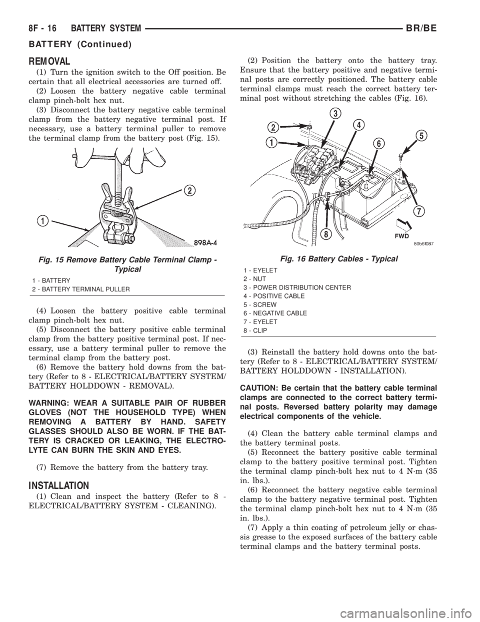
REMOVAL
(1) Turn the ignition switch to the Off position. Be
certain that all electrical accessories are turned off.
(2) Loosen the battery negative cable terminal
clamp pinch-bolt hex nut.
(3) Disconnect the battery negative cable terminal
clamp from the battery negative terminal post. If
necessary, use a battery terminal puller to remove
the terminal clamp from the battery post (Fig. 15).
(4) Loosen the battery positive cable terminal
clamp pinch-bolt hex nut.
(5) Disconnect the battery positive cable terminal
clamp from the battery positive terminal post. If nec-
essary, use a battery terminal puller to remove the
terminal clamp from the battery post.
(6) Remove the battery hold downs from the bat-
tery (Refer to 8 - ELECTRICAL/BATTERY SYSTEM/
BATTERY HOLDDOWN - REMOVAL).
WARNING: WEAR A SUITABLE PAIR OF RUBBER
GLOVES (NOT THE HOUSEHOLD TYPE) WHEN
REMOVING A BATTERY BY HAND. SAFETY
GLASSES SHOULD ALSO BE WORN. IF THE BAT-
TERY IS CRACKED OR LEAKING, THE ELECTRO-
LYTE CAN BURN THE SKIN AND EYES.
(7) Remove the battery from the battery tray.
INSTALLATION
(1) Clean and inspect the battery (Refer to 8 -
ELECTRICAL/BATTERY SYSTEM - CLEANING).(2) Position the battery onto the battery tray.
Ensure that the battery positive and negative termi-
nal posts are correctly positioned. The battery cable
terminal clamps must reach the correct battery ter-
minal post without stretching the cables (Fig. 16).
(3) Reinstall the battery hold downs onto the bat-
tery (Refer to 8 - ELECTRICAL/BATTERY SYSTEM/
BATTERY HOLDDOWN - INSTALLATION).
CAUTION: Be certain that the battery cable terminal
clamps are connected to the correct battery termi-
nal posts. Reversed battery polarity may damage
electrical components of the vehicle.
(4) Clean the battery cable terminal clamps and
the battery terminal posts.
(5) Reconnect the battery positive cable terminal
clamp to the battery positive terminal post. Tighten
the terminal clamp pinch-bolt hex nut to 4 N´m (35
in. lbs.).
(6) Reconnect the battery negative cable terminal
clamp to the battery negative terminal post. Tighten
the terminal clamp pinch-bolt hex nut to 4 N´m (35
in. lbs.).
(7) Apply a thin coating of petroleum jelly or chas-
sis grease to the exposed surfaces of the battery cable
terminal clamps and the battery terminal posts.
Fig. 15 Remove Battery Cable Terminal Clamp -
Typical
1 - BATTERY
2 - BATTERY TERMINAL PULLER
Fig. 16 Battery Cables - Typical
1 - EYELET
2 - NUT
3 - POWER DISTRIBUTION CENTER
4 - POSITIVE CABLE
5 - SCREW
6 - NEGATIVE CABLE
7 - EYELET
8 - CLIP
8F - 16 BATTERY SYSTEMBR/BE
BATTERY (Continued)
Page 407 of 2255
(5) Remove the battery hold down strap from the
top of the battery case.
INSTALLATION
(1) Clean and inspect the battery hold down hard-
ware (Refer to 8 - ELECTRICAL/BATTERY SYSTEM
- CLEANING).
(2) Position the battery hold down strap across the
top of the battery case.
(3) Install and tighten the two battery hold down
bolts through the holes on each end of the hold down
strap and into the U-nuts on each side of the battery
tray. Tighten the bolts to 4 N´m (35 in. lbs.).
(4) Reconnect the battery negative cable terminal
clamp to the battery negative terminal post. Tighten
the terminal clamp pinch-bolt hex nut to 4 N´m (35
in. lbs.).
BATTERY CABLE
DESCRIPTION
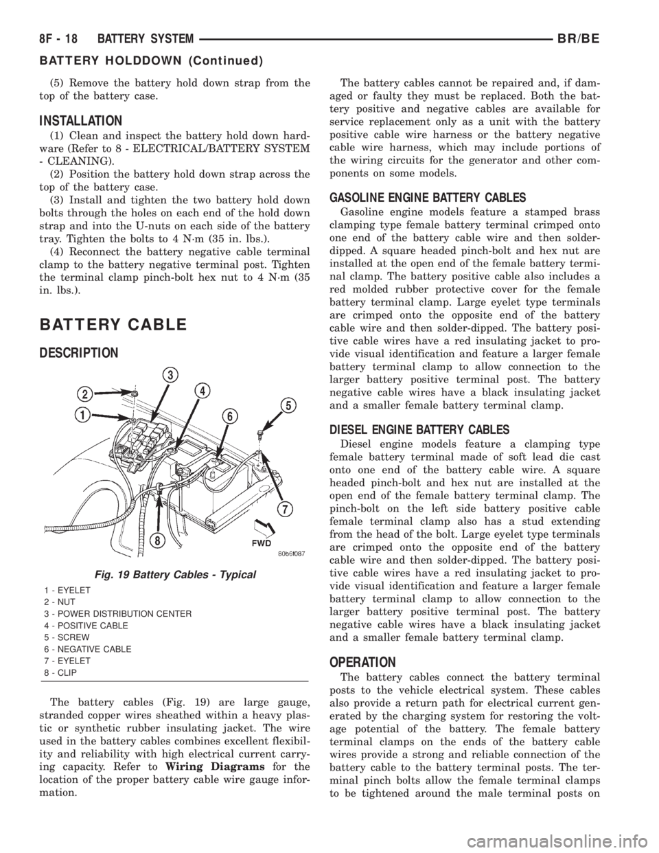
The battery cables (Fig. 19) are large gauge,
stranded copper wires sheathed within a heavy plas-
tic or synthetic rubber insulating jacket. The wire
used in the battery cables combines excellent flexibil-
ity and reliability with high electrical current carry-
ing capacity. Refer toWiring Diagramsfor the
location of the proper battery cable wire gauge infor-
mation.The battery cables cannot be repaired and, if dam-
aged or faulty they must be replaced. Both the bat-
tery positive and negative cables are available for
service replacement only as a unit with the battery
positive cable wire harness or the battery negative
cable wire harness, which may include portions of
the wiring circuits for the generator and other com-
ponents on some models.
GASOLINE ENGINE BATTERY CABLES
Gasoline engine models feature a stamped brass
clamping type female battery terminal crimped onto
one end of the battery cable wire and then solder-
dipped. A square headed pinch-bolt and hex nut are
installed at the open end of the female battery termi-
nal clamp. The battery positive cable also includes a
red molded rubber protective cover for the female
battery terminal clamp. Large eyelet type terminals
are crimped onto the opposite end of the battery
cable wire and then solder-dipped. The battery posi-
tive cable wires have a red insulating jacket to pro-
vide visual identification and feature a larger female
battery terminal clamp to allow connection to the
larger battery positive terminal post. The battery
negative cable wires have a black insulating jacket
and a smaller female battery terminal clamp.
DIESEL ENGINE BATTERY CABLES
Diesel engine models feature a clamping type
female battery terminal made of soft lead die cast
onto one end of the battery cable wire. A square
headed pinch-bolt and hex nut are installed at the
open end of the female battery terminal clamp. The
pinch-bolt on the left side battery positive cable
female terminal clamp also has a stud extending
from the head of the bolt. Large eyelet type terminals
are crimped onto the opposite end of the battery
cable wire and then solder-dipped. The battery posi-
tive cable wires have a red insulating jacket to pro-
vide visual identification and feature a larger female
battery terminal clamp to allow connection to the
larger battery positive terminal post. The battery
negative cable wires have a black insulating jacket
and a smaller female battery terminal clamp.
OPERATION
The battery cables connect the battery terminal
posts to the vehicle electrical system. These cables
also provide a return path for electrical current gen-
erated by the charging system for restoring the volt-
age potential of the battery. The female battery
terminal clamps on the ends of the battery cable
wires provide a strong and reliable connection of the
battery cable to the battery terminal posts. The ter-
minal pinch bolts allow the female terminal clamps
to be tightened around the male terminal posts on
Fig. 19 Battery Cables - Typical
1 - EYELET
2 - NUT
3 - POWER DISTRIBUTION CENTER
4 - POSITIVE CABLE
5 - SCREW
6 - NEGATIVE CABLE
7 - EYELET
8 - CLIP
8F - 18 BATTERY SYSTEMBR/BE
BATTERY HOLDDOWN (Continued)
Page 409 of 2255
VOLTAGE DROP TEST
WARNING: MODELS EQUIPPED WITH THE DIESEL
ENGINE OPTION ALSO HAVE AN AUTOMATIC
SHUTDOWN (ASD) RELAY LOCATED IN THE
POWER DISTRIBUTION CENTER (PDC), IN THE
ENGINE COMPARTMENT. HOWEVER, REMOVAL OF
THE ASD RELAY MAY NOT PREVENT THE DIESEL
ENGINE FROM STARTING. BE CERTAIN TO ALSO
DISCONNECT THE FUEL SHUTDOWN SOLENOID
WIRE HARNESS CONNECTOR ON MODELS WITH A
DIESEL ENGINE. FAILURE TO DO SO MAY RESULT
IN PERSONAL INJURY.
The following operation will require a voltmeter
accurate to 1/10 (0.10) volt. Before performing this
test, be certain that the following procedures are
accomplished:
²The battery is fully-charged and load tested
(Refer to 8 - ELECTRICAL/BATTERY SYSTEM/BAT-
TERY - STANDARD PROCEDURE).
²Fully engage the parking brake.
²If the vehicle is equipped with an automatic
transmission, place the gearshift selector lever in the
Park position. If the vehicle is equipped with a man-
ual transmission, place the gearshift selector lever in
the Neutral position and block the clutch pedal in the
fully depressed position.
²Verify that all lamps and accessories are turned
off.
²To prevent a gasoline engine from starting,
remove the Automatic ShutDown (ASD) relay. The
ASD relay is located in the Power Distribution Cen-
ter (PDC), in the engine compartment. See the fuse
and relay layout label affixed to the underside of the
PDC cover for ASD relay identification and location.
To prevent a diesel engine from starting, disconnect
the fuel shutdown solenoid wire harness connector
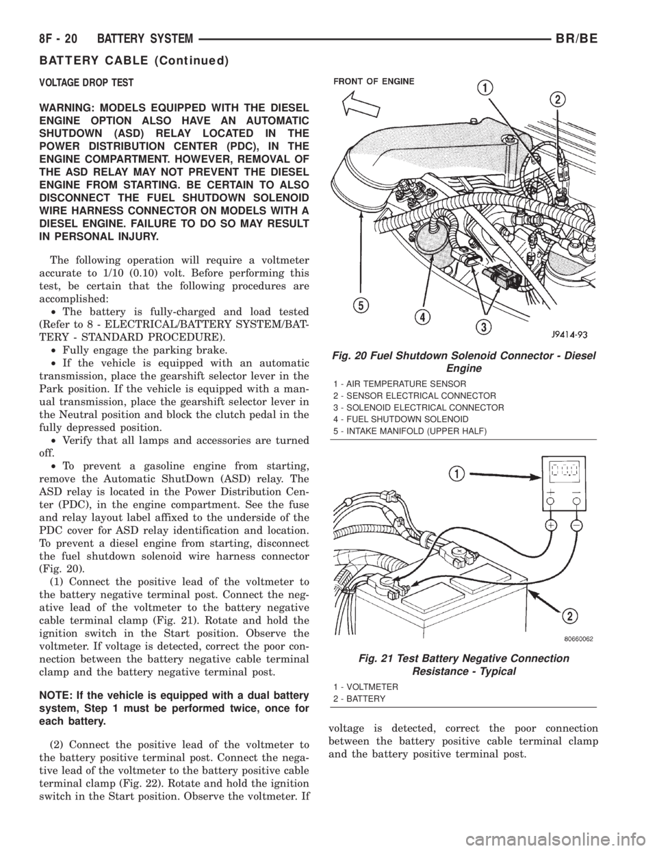
(Fig. 20).
(1) Connect the positive lead of the voltmeter to
the battery negative terminal post. Connect the neg-
ative lead of the voltmeter to the battery negative
cable terminal clamp (Fig. 21). Rotate and hold the
ignition switch in the Start position. Observe the
voltmeter. If voltage is detected, correct the poor con-
nection between the battery negative cable terminal
clamp and the battery negative terminal post.
NOTE: If the vehicle is equipped with a dual battery
system, Step 1 must be performed twice, once for
each battery.
(2) Connect the positive lead of the voltmeter to
the battery positive terminal post. Connect the nega-
tive lead of the voltmeter to the battery positive cable
terminal clamp (Fig. 22). Rotate and hold the ignition
switch in the Start position. Observe the voltmeter. Ifvoltage is detected, correct the poor connection
between the battery positive cable terminal clamp
and the battery positive terminal post.
Fig. 20 Fuel Shutdown Solenoid Connector - Diesel
Engine
1 - AIR TEMPERATURE SENSOR
2 - SENSOR ELECTRICAL CONNECTOR
3 - SOLENOID ELECTRICAL CONNECTOR
4 - FUEL SHUTDOWN SOLENOID
5 - INTAKE MANIFOLD (UPPER HALF)
Fig. 21 Test Battery Negative Connection
Resistance - Typical
1 - VOLTMETER
2 - BATTERY
8F - 20 BATTERY SYSTEMBR/BE
BATTERY CABLE (Continued)
Page 415 of 2255
²a faulty or improperly adjusted switch that
allows a lamp to stay on. Refer to Ignition-Off Draw
Test in 8, Battery for more information.
INSPECTION
The Powertrain Control Module (PCM) monitors
critical input and output circuits of the charging sys-
tem, making sure they are operational. A Diagnostic
Trouble Code (DTC) is assigned to each input and
output circuit monitored by the On-Board Diagnostic
(OBD) system. Some charging system circuits are
checked continuously, and some are checked only
under certain conditions.
Refer to Diagnostic Trouble Codes in; Powertrain
Control Module; Electronic Control Modules for more
DTC information. This will include a complete list of
DTC's including DTC's for the charging system.
To perform a complete test of the charging system,
refer to the appropriate Powertrain Diagnostic Proce-
dures service manual and the DRBtscan tool. Per-
form the following inspections before attaching the
scan tool.
(1) Inspect the battery condition. Refer to 8, Bat-
tery for procedures.(2) Inspect condition of battery cable terminals,
battery posts, connections at engine block, starter
solenoid and relay. They should be clean and tight.
Repair as required.
(3) Inspect all fuses in both the fuseblock and
Power Distribution Center (PDC) for tightness in
receptacles. They should be properly installed and
tight. Repair or replace as required.
(4) Inspect generator mounting bolts for tightness.
Replace or tighten bolts if required. Refer to the Gen-
erator Removal/Installation section of this group for
torque specifications.
(5) Inspect generator drive belt condition and ten-
sion. Tighten or replace belt as required. Refer to
Belt Tension Specifications in 7, Cooling System.
(6) Inspect automatic belt tensioner (if equipped).
Refer to 7, Cooling System for information.
(7) Inspect generator electrical connections at gen-
erator field, battery output, and ground terminal (if
equipped). Also check generator ground wire connec-
tion at engine (if equipped). They should all be clean
and tight. Repair as required.
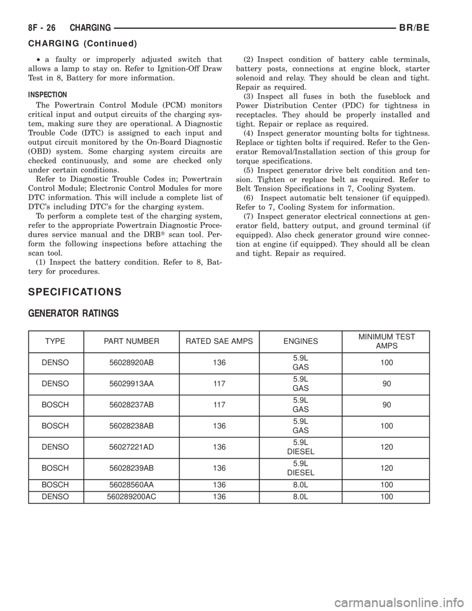
SPECIFICATIONS
GENERATOR RATINGS
TYPE PART NUMBER RATED SAE AMPS ENGINESMINIMUM TEST
AMPS
DENSO 56028920AB 1365.9L
GAS100
DENSO 56029913AA 1175.9L
GAS90
BOSCH 56028237AB 1175.9L
GAS90
BOSCH 56028238AB 1365.9L
GAS100
DENSO 56027221AD 1365.9L
DIESEL120
BOSCH 56028239AB 1365.9L
DIESEL120
BOSCH 56028560AA 136 8.0L 100
DENSO 560289200AC 136 8.0L 100
8F - 26 CHARGINGBR/BE
CHARGING (Continued)
Page 423 of 2255
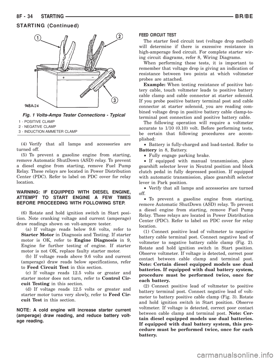
(4) Verify that all lamps and accessories are
turned off.
(5) To prevent a gasoline engine from starting,
remove Automatic ShutDown (ASD) relay. To prevent
a diesel engine from starting, remove Fuel Pump
Relay. These relays are located in Power Distribution
Center (PDC). Refer to label on PDC cover for relay
location.
WARNING: IF EQUIPPED WITH DIESEL ENGINE,
ATTEMPT TO START ENGINE A FEW TIMES
BEFORE PROCEEDING WITH FOLLOWING STEP.
(6) Rotate and hold ignition switch in Start posi-
tion. Note cranking voltage and current (amperage)
draw readings shown on volt-ampere tester.
(a) If voltage reads below 9.6 volts, refer to
Starter Motorin Diagnosis and Testing. If starter
motor is OK, refer toEngine Diagnosisin 9,
Engine for further testing of engine. If starter
motor is not OK, replace faulty starter motor.
(b) If voltage reads above 9.6 volts and current
(amperage) draw reads below specifications, refer
toFeed Circuit Testin this section.
(c) If voltage reads 12.5 volts or greater and
starter motor does not turn, refer toControl Cir-
cuit Testingin this section.
(d) If voltage reads 12.5 volts or greater and
starter motor turns very slowly, refer toFeed Cir-
cuit Testin this section.
NOTE: A cold engine will increase starter current
(amperage) draw reading, and reduce battery volt-
age reading.FEED CIRCUIT TEST
The starter feed circuit test (voltage drop method)
will determine if there is excessive resistance in
high-amperage feed circuit. For complete starter wir-
ing circuit diagrams, refer 8, Wiring Diagrams.
When performing these tests, it is important to
remember that voltage drop is giving an indication of
resistance between two points at which voltmeter
probes are attached.
Example:When testing resistance of positive bat-
tery cable, touch voltmeter leads to positive battery
cable clamp and cable connector at starter solenoid.
If you probe positive battery terminal post and cable
connector at starter solenoid, you are reading com-
bined voltage drop in positive battery cable clamp-to-
terminal post connection and positive battery cable.
The following operation will require a voltmeter
accurate to 1/10 (0.10) volt. Before performing tests,
be certain that following procedures are accom-
plished:
²Battery is fully-charged and load-tested. Refer to
Batteryin 8, Battery.
²Fully engage parking brake.
²If equipped with manual transmission, place
gearshift selector lever in Neutral position and block
clutch pedal in fully depressed position. If equipped
with automatic transmission, place gearshift selector
lever in Park position.
²Verify that all lamps and accessories are turned
off.
²To prevent a gasoline engine from starting,
remove Automatic ShutDown (ASD) relay. To prevent
a diesel engine from starting, remove Fuel Pump
Relay. These relays are located in Power Distribution
Center (PDC). Refer to label on PDC cover for relay
location.
(1) Connect positive lead of voltmeter to negative
battery cable terminal post. Connect negative lead of
voltmeter to negative battery cable clamp (Fig. 2).
Rotate and hold ignition switch in Start position.
Observe voltmeter. If voltage is detected, correct poor
contact between cable clamp and terminal post.
Note: Certain diesel equipped models use dual
batteries. If equipped with dual battery system,
procedure must be performed twice, once for
each battery.
(2) Connect positive lead of voltmeter to positive
battery terminal post. Connect negative lead of volt-
meter to battery positive cable clamp (Fig. 3). Rotate
and hold ignition switch in Start position. Observe
voltmeter. If voltage is detected, correct poor contact
between cable clamp and terminal post.Note: Cer-
tain diesel equipped models use dual batteries.
If equipped with dual battery system, this pro-
cedure must be performed twice, once for each
battery.
Fig. 1 Volts-Amps Tester Connections - Typical
1 - POSITIVE CLAMP
2 - NEGATIVE CLAMP
3 - INDUCTION AMMETER CLAMP
8F - 34 STARTINGBR/BE
STARTING (Continued)
Page 430 of 2255
STARTER MOTOR RELAY
DESCRIPTION
The starter relay is an electromechanical device
that switches battery current to the pull-in coil of the
starter solenoid when ignition switch is turned to
Start position. The starter relay is located in the
Power Distribution Center (PDC) in the engine com-
partment. See PDC cover for relay identification and
location.
The starter relay is a International Standards
Organization (ISO) relay. Relays conforming to ISO
specifications have common physical dimensions, cur-
rent capacities, terminal patterns, and terminal func-
tions.
The starter relay cannot be repaired or adjusted
and, if faulty or damaged, it must be replaced.
OPERATION
The ISO relay consists of an electromagnetic coil, a
resistor or diode, and three (two fixed and one mov-
able) electrical contacts. The movable (common feed)
relay contact is held against one of the fixed contacts
(normally closed) by spring pressure. When electro-
magnetic coil is energized, it draws the movable con-
tact away from normally closed fixed contact, and
holds it against the other (normally open) fixed con-
tact.
When electromagnetic coil is de-energized, spring
pressure returns movable contact to normally closed
position. The resistor or diode is connected in parallel
with electromagnetic coil within relay, and helps to
dissipate voltage spikes produced when coil is de-en-
ergized.
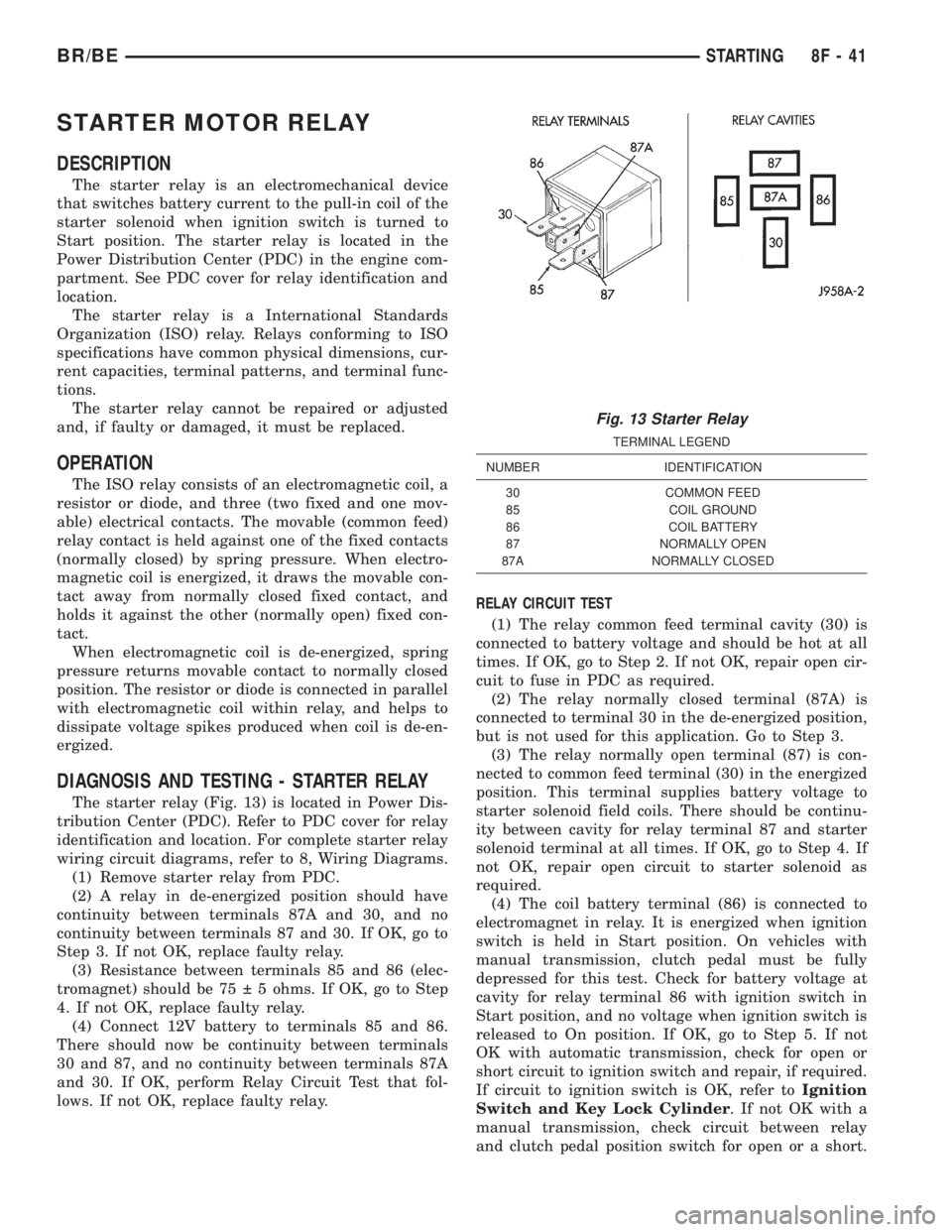
DIAGNOSIS AND TESTING - STARTER RELAY
The starter relay (Fig. 13) is located in Power Dis-
tribution Center (PDC). Refer to PDC cover for relay
identification and location. For complete starter relay
wiring circuit diagrams, refer to 8, Wiring Diagrams.
(1) Remove starter relay from PDC.
(2) A relay in de-energized position should have
continuity between terminals 87A and 30, and no
continuity between terminals 87 and 30. If OK, go to
Step 3. If not OK, replace faulty relay.
(3) Resistance between terminals 85 and 86 (elec-
tromagnet) should be 75 5 ohms. If OK, go to Step
4. If not OK, replace faulty relay.
(4) Connect 12V battery to terminals 85 and 86.
There should now be continuity between terminals
30 and 87, and no continuity between terminals 87A
and 30. If OK, perform Relay Circuit Test that fol-
lows. If not OK, replace faulty relay.RELAY CIRCUIT TEST
(1) The relay common feed terminal cavity (30) is
connected to battery voltage and should be hot at all
times. If OK, go to Step 2. If not OK, repair open cir-
cuit to fuse in PDC as required.
(2) The relay normally closed terminal (87A) is
connected to terminal 30 in the de-energized position,
but is not used for this application. Go to Step 3.
(3) The relay normally open terminal (87) is con-
nected to common feed terminal (30) in the energized
position. This terminal supplies battery voltage to
starter solenoid field coils. There should be continu-
ity between cavity for relay terminal 87 and starter
solenoid terminal at all times. If OK, go to Step 4. If
not OK, repair open circuit to starter solenoid as
required.
(4) The coil battery terminal (86) is connected to
electromagnet in relay. It is energized when ignition
switch is held in Start position. On vehicles with
manual transmission, clutch pedal must be fully
depressed for this test. Check for battery voltage at
cavity for relay terminal 86 with ignition switch in
Start position, and no voltage when ignition switch is
released to On position. If OK, go to Step 5. If not
OK with automatic transmission, check for open or
short circuit to ignition switch and repair, if required.
If circuit to ignition switch is OK, refer toIgnition
Switch and Key Lock Cylinder. If not OK with a
manual transmission, check circuit between relay
and clutch pedal position switch for open or a short.
Fig. 13 Starter Relay
TERMINAL LEGEND
NUMBER IDENTIFICATION
30 COMMON FEED
85 COIL GROUND
86 COIL BATTERY
87 NORMALLY OPEN
87A NORMALLY CLOSED
BR/BESTARTING 8F - 41