steering gear DODGE RAM 2002 Service Repair Manual
[x] Cancel search | Manufacturer: DODGE, Model Year: 2002, Model line: RAM, Model: DODGE RAM 2002Pages: 2255, PDF Size: 62.07 MB
Page 19 of 2255
DESCRIPTION - AUTOMATIC TRANSMISSION
FLUID
NOTE: Refer to the maintenance schedules in this
group for the recommended maintenance (fluid/filter
change) intervals for this transmission.
NOTE: Refer to Service Procedures in this group for
fluid level checking procedures.
MopartATF +4, type 9602, Automatic Transmis-
sion Fluid is the recommended fluid for
DaimlerChrysler automatic transmissions.
Dexron II fluid IS NOT recommended. Clutch
chatter can result from the use of improper
fluid.
MopartATF +4, type 9602, Automatic Transmis-
sion Fluid when new is red in color. The ATF is dyed
red so it can be identified from other fluids used in
the vehicle such as engine oil or antifreeze. The red
color is not permanent and is not an indicator of fluid
condition. As the vehicle is driven, the ATF will begin
to look darker in color and may eventually become
brown.This is normal.A dark brown/black fluid
accompanied with a burnt odor and/or deterioration
in shift quality may indicate fluid deterioration or
transmission component failure.
FLUID ADDITIVES
DaimlerChrysler strongly recommends against the
addition of any fluids to the transmission, other than
those automatic transmission fluids listed above.
Exceptions to this policy are the use of special dyes
to aid in detecting fluid leaks.
Various ªspecialº additives and supplements exist
that claim to improve shift feel and/or quality. These
additives and others also claim to improve converter
clutch operation and inhibit overheating, oxidation,
varnish, and sludge. These claims have not been sup-
ported to the satisfaction of DaimlerChrysler and
these additivesmust not be used.The use of trans-
mission ªsealersº should also be avoided, since they
may adversely affect the integrity of transmission
seals.
OPERATION - AUTOMATIC TRANSMISSION
FLUID
The automatic transmission fluid is selected based
upon several qualities. The fluid must provide a high
level of protection for the internal components by
providing a lubricating film between adjacent metal
components. The fluid must also be thermally stable
so that it can maintain a consistent viscosity through
a large temperature range. If the viscosity stays con-
stant through the temperature range of operation,transmission operation and shift feel will remain con-
sistent. Transmission fluid must also be a good con-
ductor of heat. The fluid must absorb heat from the
internal transmission components and transfer that
heat to the transmission case.
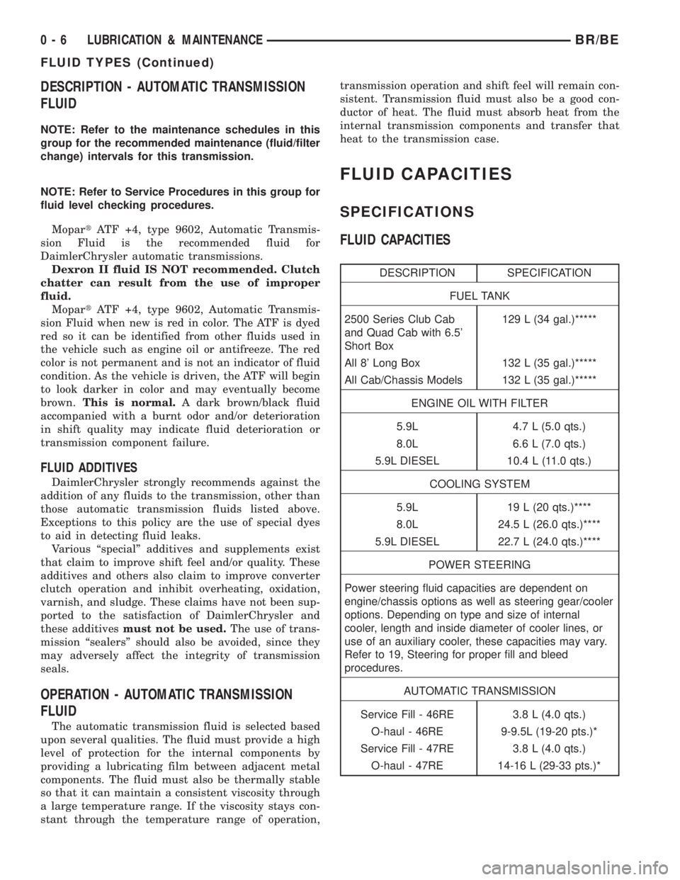
FLUID CAPACITIES
SPECIFICATIONS
FLUID CAPACITIES
DESCRIPTION SPECIFICATION
FUEL TANK
2500 Series Club Cab
and Quad Cab with 6.5'
Short Box129 L (34 gal.)*****
All 8' Long Box 132 L (35 gal.)*****
All Cab/Chassis Models 132 L (35 gal.)*****
ENGINE OIL WITH FILTER
5.9L 4.7 L (5.0 qts.)
8.0L 6.6 L (7.0 qts.)
5.9L DIESEL 10.4 L (11.0 qts.)
COOLING SYSTEM
5.9L 19 L (20 qts.)****
8.0L 24.5 L (26.0 qts.)****
5.9L DIESEL 22.7 L (24.0 qts.)****
POWER STEERING
Power steering fluid capacities are dependent on
engine/chassis options as well as steering gear/cooler
options. Depending on type and size of internal
cooler, length and inside diameter of cooler lines, or
use of an auxiliary cooler, these capacities may vary.
Refer to 19, Steering for proper fill and bleed
procedures.
AUTOMATIC TRANSMISSION
Service Fill - 46RE 3.8 L (4.0 qts.)
O-haul - 46RE 9-9.5L (19-20 pts.)*
Service Fill - 47RE 3.8 L (4.0 qts.)
O-haul - 47RE 14-16 L (29-33 pts.)*
0 - 6 LUBRICATION & MAINTENANCEBR/BE
FLUID TYPES (Continued)
Page 27 of 2255
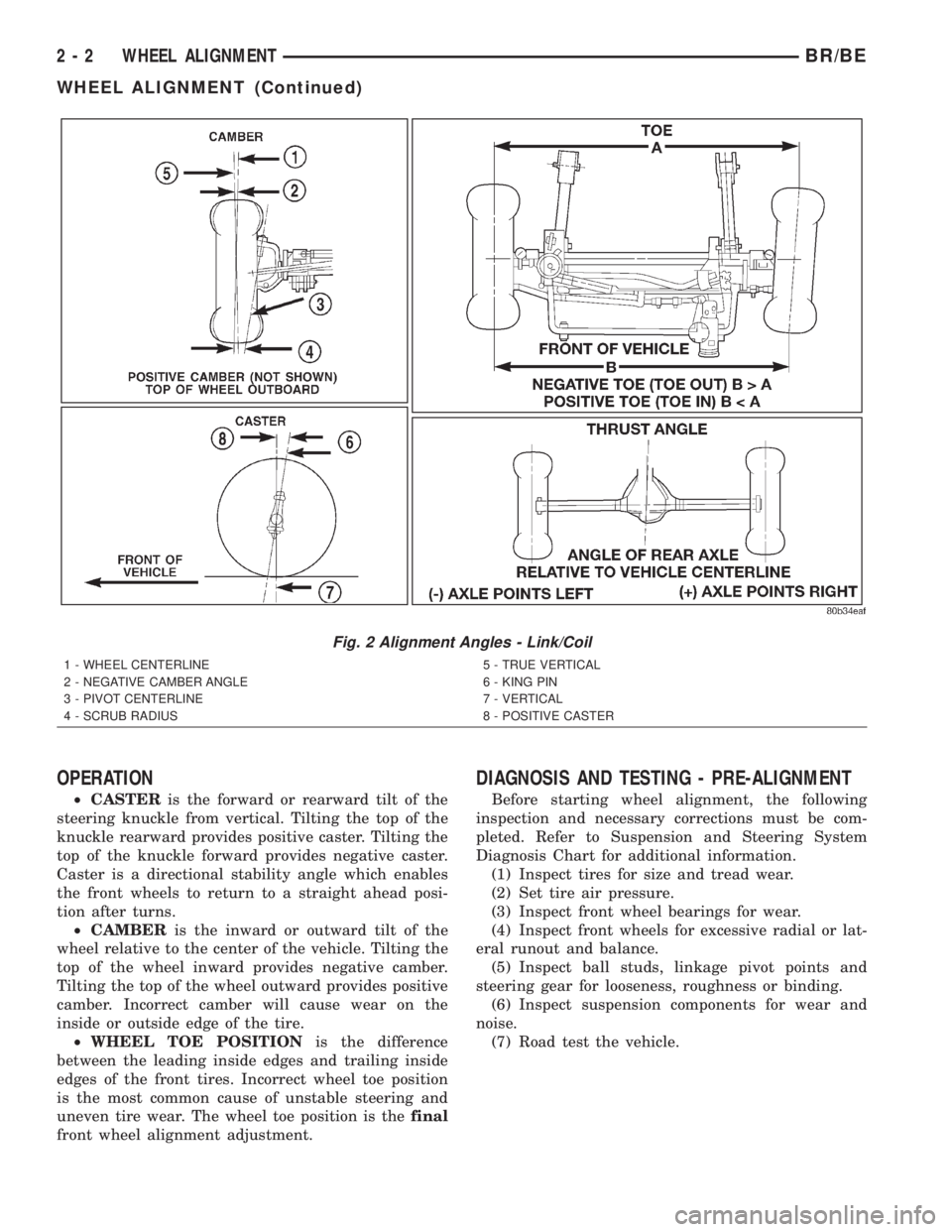
OPERATION
²CASTERis the forward or rearward tilt of the
steering knuckle from vertical. Tilting the top of the
knuckle rearward provides positive caster. Tilting the
top of the knuckle forward provides negative caster.
Caster is a directional stability angle which enables
the front wheels to return to a straight ahead posi-
tion after turns.
²CAMBERis the inward or outward tilt of the
wheel relative to the center of the vehicle. Tilting the
top of the wheel inward provides negative camber.
Tilting the top of the wheel outward provides positive
camber. Incorrect camber will cause wear on the
inside or outside edge of the tire.
²WHEEL TOE POSITIONis the difference
between the leading inside edges and trailing inside
edges of the front tires. Incorrect wheel toe position
is the most common cause of unstable steering and
uneven tire wear. The wheel toe position is thefinal
front wheel alignment adjustment.
DIAGNOSIS AND TESTING - PRE-ALIGNMENT
Before starting wheel alignment, the following
inspection and necessary corrections must be com-
pleted. Refer to Suspension and Steering System
Diagnosis Chart for additional information.
(1) Inspect tires for size and tread wear.
(2) Set tire air pressure.
(3) Inspect front wheel bearings for wear.
(4) Inspect front wheels for excessive radial or lat-
eral runout and balance.
(5) Inspect ball studs, linkage pivot points and
steering gear for looseness, roughness or binding.
(6) Inspect suspension components for wear and
noise.
(7) Road test the vehicle.
Fig. 2 Alignment Angles - Link/Coil
1 - WHEEL CENTERLINE
2 - NEGATIVE CAMBER ANGLE
3 - PIVOT CENTERLINE
4 - SCRUB RADIUS5 - TRUE VERTICAL
6 - KING PIN
7 - VERTICAL
8 - POSITIVE CASTER
2 - 2 WHEEL ALIGNMENTBR/BE
WHEEL ALIGNMENT (Continued)
Page 73 of 2255
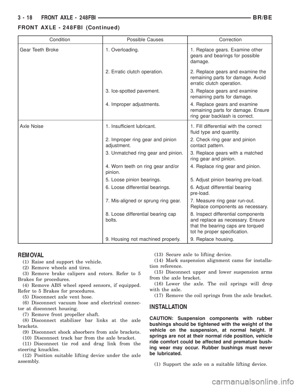
Condition Possible Causes Correction
Gear Teeth Broke 1. Overloading. 1. Replace gears. Examine other
gears and bearings for possible
damage.
2. Erratic clutch operation. 2. Replace gears and examine the
remaining parts for damage. Avoid
erratic clutch operation.
3. Ice-spotted pavement. 3. Replace gears and examine
remaining parts for damage.
4. Improper adjustments. 4. Replace gears and examine
remaining parts for damage. Ensure
ring gear backlash is correct.
Axle Noise 1. Insufficient lubricant. 1. Fill differential with the correct
fluid type and quantity.
2. Improper ring gear and pinion
adjustment.2. Check ring gear and pinion
contact pattern.
3. Unmatched ring gear and pinion. 3. Replace gears with a matched
ring gear and pinion.
4. Worn teeth on ring gear and/or
pinion.4. Replace ring gear and pinion.
5. Loose pinion bearings. 5. Adjust pinion bearing pre-load.
6. Loose differential bearings. 6. Adjust differential bearing
pre-load.
7. Mis-aligned or sprung ring gear. 7. Measure ring gear run-out.
Replace components as necessary.
8. Loose differential bearing cap
bolts.8. Inspect differential components
and replace as necessary. Ensure
that the bearing caps are torqued
tot he proper specification.
9. Housing not machined properly. 9. Replace housing.
REMOVAL
(1) Raise and support the vehicle.
(2) Remove wheels and tires.
(3) Remove brake calipers and rotors. Refer to 5
Brakes for procedures.
(4) Remove ABS wheel speed sensors, if equipped.
Refer to 5 Brakes for procedures.
(5) Disconnect axle vent hose.
(6) Disconnect vacuum hose and electrical connec-
tor at disconnect housing.
(7) Remove front propeller shaft.
(8) Disconnect stabilizer bar links at the axle
brackets.
(9) Disconnect shock absorbers from axle brackets.
(10) Disconnect track bar from the axle bracket.
(11) Disconnect tie rod and drag link from the
steering knuckles.
(12) Position suitable lifting device under the axle
assembly.(13) Secure axle to lifting device.
(14) Mark suspension alignment cams for installa-
tion reference.
(15) Disconnect upper and lower suspension arms
from the axle bracket.
(16) Lower the axle. The coil springs will drop
with the axle.
(17) Remove the coil springs from the axle bracket.
INSTALLATION
CAUTION: Suspension components with rubber
bushings should be tightened with the weight of the
vehicle on the suspension, at normal height. If
springs are not at their normal ride position, vehicle
ride comfort could be affected and premature bush-
ing wear may occur. Rubber bushings must never
be lubricated.
(1) Support the axle on a suitable lifting device.
3 - 18 FRONT AXLE - 248FBIBR/BE
FRONT AXLE - 248FBI (Continued)
Page 74 of 2255
(2) Secure axle to lifting device.
(3) Position the axle under the vehicle.
(4) Install springs, retainer clip and bolts.
(5) Raise axle and align it with the spring pads.
(6) Position upper and lower suspension arms in
the axle brackets. Install bolts, nuts and align the
suspension alignment cams to the reference marks.
Do not tighten at this time.
(7) Connect track bar to the axle bracket and
install the bolt. Do not tighten at this time.
(8) Install shock absorber and tighten bolts to 121
N´m (89 ft. lbs.).
(9) Install stabilizer bar link to the axle bracket.
Tighten the nut to 37 N´m (27 ft. lbs.).
(10) Install drag link and tie rod to the steering
knuckles and tighten the nuts to 88 N´m (65 ft. lbs.).
(11) Install ABS wheel speed sensors, if equipped.
Refer to 5 Brakes for procedures.
(12) Install rotors and brake calipers, refer to 5
Brakes for procedures.
(13) Connect the vent hose to the tube fitting.
(14) Connect vacuum hose and electrical connector
to disconnect housing.
(15) Install front propeller shaft.
(16) Check and add differential lubricant, if neces-
sary. Refer to Lubricant Specifications for lubricant
requirements.
(17) Install wheel and tire assemblies.
(18) Remove supports and lower the vehicle.
(19) Tighten upper suspension arm nuts at axle to
121 N´m (89 ft. lbs.). Tighten upper suspension arm
nuts at frame to 84 N´m (62 ft. lbs.).
(20) Tighten lower suspension arm nuts at axle to
84 N´m (62 ft. lbs.). Tighten the lower suspension
arm nuts at frame to 119 N´m (88 ft. lbs.).
(21) Tighten track bar bolt at the axle bracket to
176 N´m (130 ft. lbs.).
(22) Check front wheel alignment.
ADJUSTMENTS
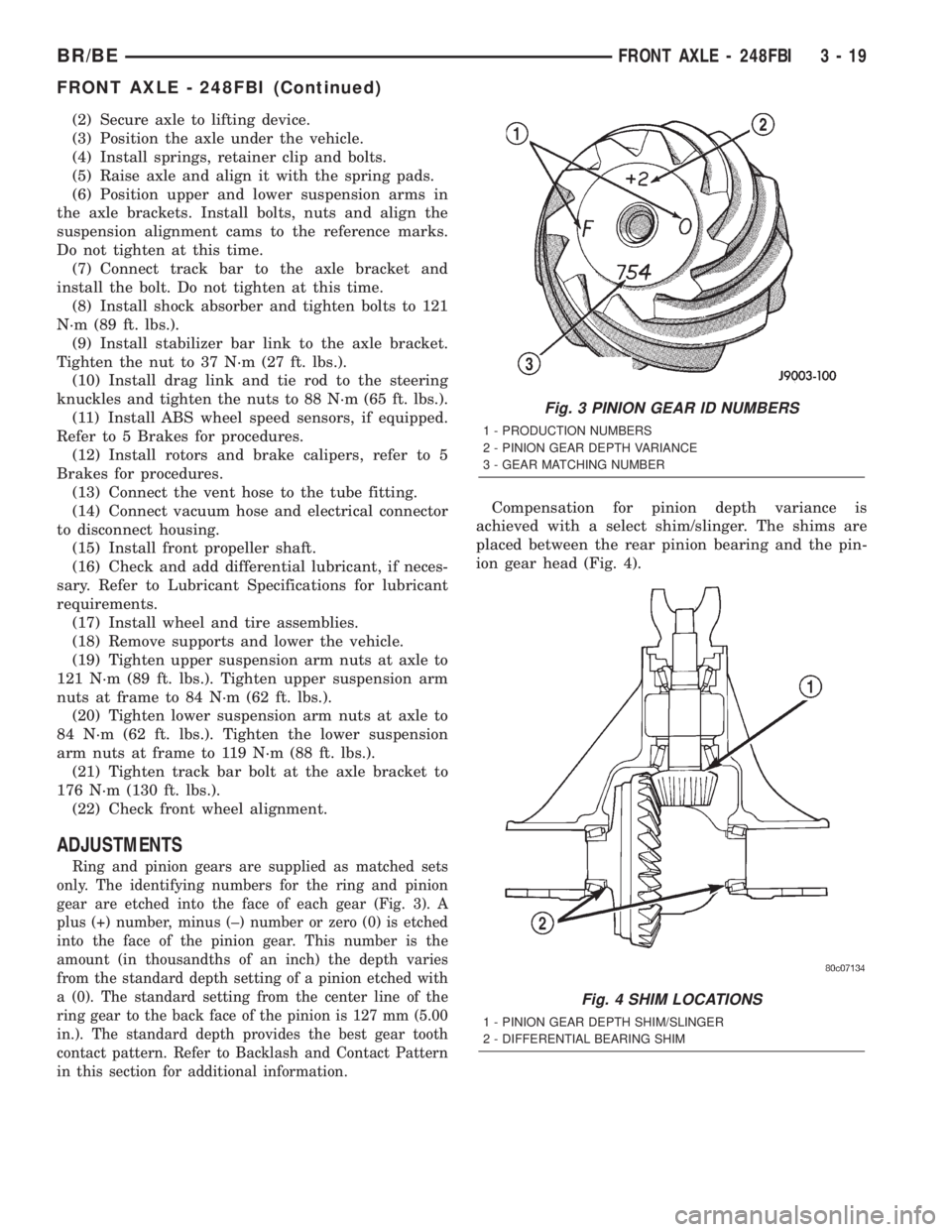
Ring and pinion gears are supplied as matched sets
only. The identifying numbers for the ring and pinion
gear are etched into the face of each gear (Fig. 3). A
plus (+) number, minus (±) number or zero (0) is etched
into the face of the pinion gear. This number is the
amount (in thousandths of an inch) the depth varies
from the standard depth setting of a pinion etched with
a (0). The standard setting from the center line of the
ring gear to the back face of the pinion is 127 mm (5.00
in.). The standard depth provides the best gear tooth
contact pattern. Refer to Backlash and Contact Pattern
in this section for additional information.
Compensation for pinion depth variance is
achieved with a select shim/slinger. The shims are
placed between the rear pinion bearing and the pin-
ion gear head (Fig. 4).
Fig. 3 PINION GEAR ID NUMBERS
1 - PRODUCTION NUMBERS
2 - PINION GEAR DEPTH VARIANCE
3 - GEAR MATCHING NUMBER
Fig. 4 SHIM LOCATIONS
1 - PINION GEAR DEPTH SHIM/SLINGER
2 - DIFFERENTIAL BEARING SHIM
BR/BEFRONT AXLE - 248FBI 3 - 19
FRONT AXLE - 248FBI (Continued)
Page 84 of 2255
AXLE SHAFTS
REMOVAL
(1) Raise and support the vehicle.
(2) Remove wheel and tire assembly.
(3) Remove brake caliper, rotor and ABS wheel
speed sensor if equipped. Refer to 5 Brakes for pro-
cedures.
(4) Remove the cotter pin and axle hub nut.
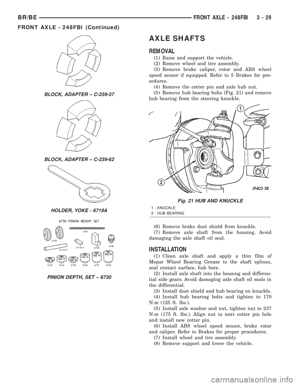
(5) Remove hub bearing bolts (Fig. 21) and remove
hub bearing from the steering knuckle.
(6) Remove brake dust shield from knuckle.
(7) Remove axle shaft from the housing. Avoid
damaging the axle shaft oil seal.
INSTALLATION
(1) Clean axle shaft and apply a thin film of
Mopar Wheel Bearing Grease to the shaft splines,
seal contact surface, hub bore.
(2) Install axle shaft into the housing and differen-
tial side gears. Avoid damaging axle shaft oil seals in
the differential.
(3) Install dust shield and hub bearing on knuckle.
(4) Install hub bearing bolts and tighten to 170
N´m (125 ft. lbs.).
(5) Install axle washer and nut, tighten nut to 237
N´m (175 ft. lbs.). Align nut to next cotter pin hole
and install new cotter pin.
(6) Install ABS wheel speed sensor, brake rotor
and caliper. Refer to Brakes for proper procedures.
(7) Install wheel and tire assembly.
(8) Remove support and lower the vehicle.
BLOCK, ADAPTER ± C-239-37
BLOCK, ADAPTER ± C-239-62
HOLDER, YOKE - 6719A
PINION DEPTH, SET ± 6730
Fig. 21 HUB AND KNUCKLE
1 - KNUCKLE
2 - HUB BEARING
BR/BEFRONT AXLE - 248FBI 3 - 29
FRONT AXLE - 248FBI (Continued)
Page 207 of 2255
EXTERIOR/BRAKE LAMP SWITCH - INSTALLA-
TION).
(10) Install knee bolster, (Refer to 23 - BODY/IN-
STRUMENT PANEL/STEERING COLUMN OPEN-
ING COVER - INSTALLATION).
POWER BRAKE BOOSTER
DIAGNOSIS AND TESTING - HYDRAULIC
BOOSTER
The hydraulic booster uses hydraulic pressure from
the power steering pump. Before diagnosing a
booster problem, first verify the power steering pump
is operating properly. Perform the following checks.
²Check the power steering fluid level.
²Check the brake fluid level.
²Check all power steering hoses and lines for
leaks and restrictions.
²Check power steering pump pressure.
NOISES
The hydraulic booster unit will produce certain
characteristic booster noises. The noises may occur
when the brake pedal is used in a manner not asso-
ciated with normal braking or driving habits.
HISSING
A hissing noise may be noticed when above normal
brake pedal pressure is applied, 40 lbs. or above. The
noise will be more noticeable if the vehicle is not
moving. The noise will increase with the brake pedal
pressure and an increase of system operating temper-
ature.
CLUNK-CHATTER-CLICKING
A clunk-chatter-clicking may be noticed when the
brake pedal is released quickly, after above normal
brake pedal pressure is applied 50-100 lbs..
BOOSTER FUNCTION TEST
With the engine off depress the brake pedal several
times to discharge the accumulator. Then depress the
brake pedal using 40 lbs. of force and start the
engine. The brake pedal should fall and then push
back against your foot. This indicates the booster is
operating properly.
ACCUMULATOR LEAKDOWN
(1) Start the engine, apply the brakes and turn the
steering wheel from lock to lock. This will ensure the
accumulator is charged. Turn off the engine and let
the vehicle sit for one hour. After one hour there
should be at least two power assisted brake applica-
tion with the engine off. If the system does not retain
a charge the booster must be replaced.(2) With the engine off depress the brake pedal
several times to discharge the accumulator. Grasp
the accumulator and see if it wobbles or turns. If it
does the accumulator has lost a gas charge and the
booster must be replaced.
SEAL LEAKAGE
If the booster leaks from any of the seals the
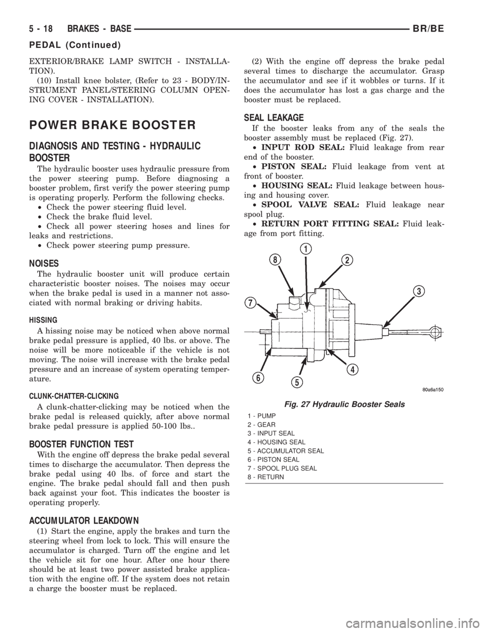
booster assembly must be replaced (Fig. 27).
²INPUT ROD SEAL:Fluid leakage from rear
end of the booster.
²PISTON SEAL:Fluid leakage from vent at
front of booster.
²HOUSING SEAL:Fluid leakage between hous-
ing and housing cover.
²SPOOL VALVE SEAL:Fluid leakage near
spool plug.
²RETURN PORT FITTING SEAL:Fluid leak-
age from port fitting.
Fig. 27 Hydraulic Booster Seals
1 - PUMP
2 - GEAR
3 - INPUT SEAL
4 - HOUSING SEAL
5 - ACCUMULATOR SEAL
6 - PISTON SEAL
7 - SPOOL PLUG SEAL
8 - RETURN
5 - 18 BRAKES - BASEBR/BE
PEDAL (Continued)
Page 209 of 2255
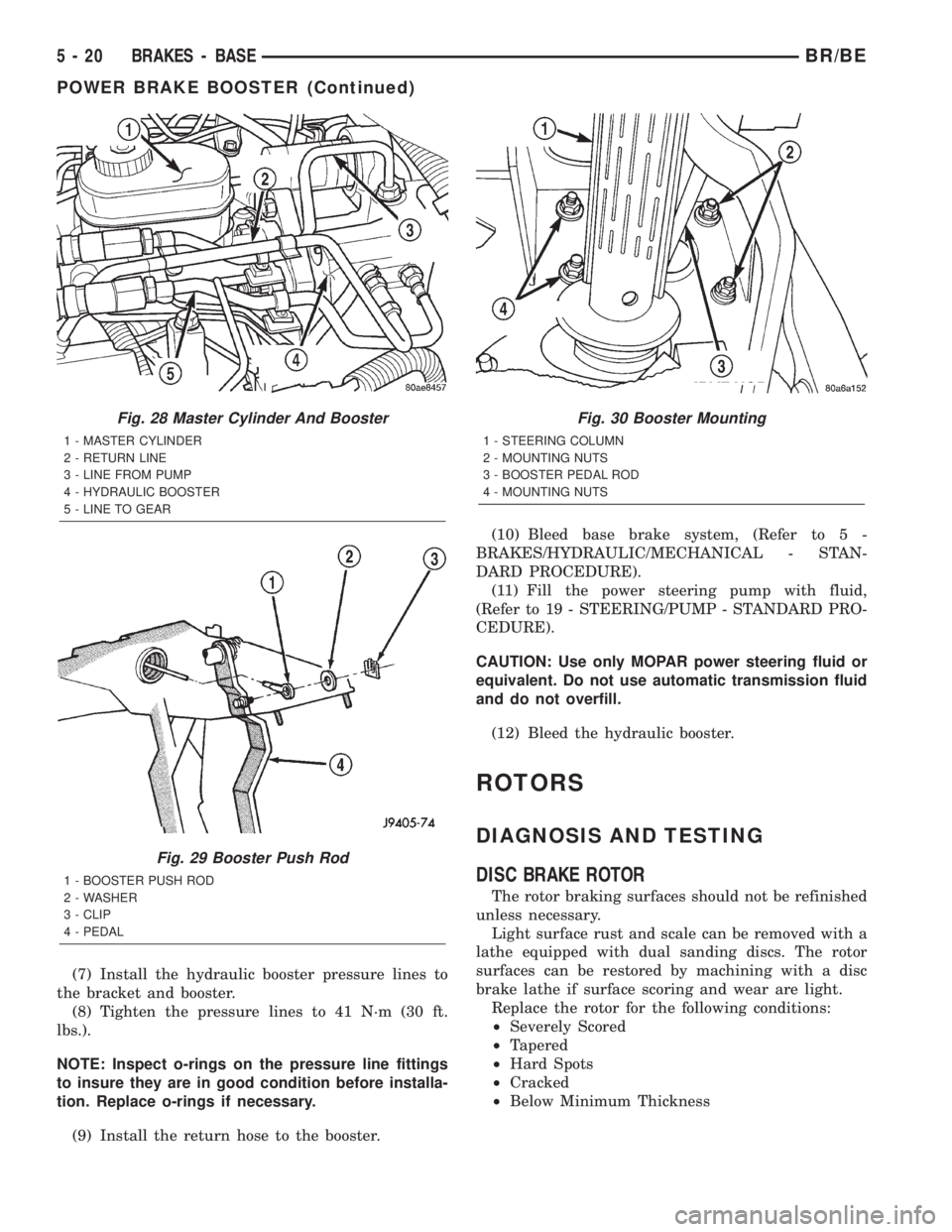
(7) Install the hydraulic booster pressure lines to
the bracket and booster.
(8) Tighten the pressure lines to 41 N´m (30 ft.
lbs.).
NOTE: Inspect o-rings on the pressure line fittings
to insure they are in good condition before installa-
tion. Replace o-rings if necessary.
(9) Install the return hose to the booster.(10) Bleed base brake system, (Refer to 5 -
BRAKES/HYDRAULIC/MECHANICAL - STAN-
DARD PROCEDURE).
(11) Fill the power steering pump with fluid,
(Refer to 19 - STEERING/PUMP - STANDARD PRO-
CEDURE).
CAUTION: Use only MOPAR power steering fluid or
equivalent. Do not use automatic transmission fluid
and do not overfill.
(12) Bleed the hydraulic booster.
ROTORS
DIAGNOSIS AND TESTING
DISC BRAKE ROTOR
The rotor braking surfaces should not be refinished
unless necessary.
Light surface rust and scale can be removed with a
lathe equipped with dual sanding discs. The rotor
surfaces can be restored by machining with a disc
brake lathe if surface scoring and wear are light.
Replace the rotor for the following conditions:
²Severely Scored
²Tapered
²Hard Spots
²Cracked
²Below Minimum Thickness
Fig. 28 Master Cylinder And Booster
1 - MASTER CYLINDER
2 - RETURN LINE
3 - LINE FROM PUMP
4 - HYDRAULIC BOOSTER
5 - LINE TO GEAR
Fig. 29 Booster Push Rod
1 - BOOSTER PUSH ROD
2 - WASHER
3 - CLIP
4 - PEDAL
Fig. 30 Booster Mounting
1 - STEERING COLUMN
2 - MOUNTING NUTS
3 - BOOSTER PEDAL ROD
4 - MOUNTING NUTS
5 - 20 BRAKES - BASEBR/BE
POWER BRAKE BOOSTER (Continued)
Page 227 of 2255
FRONT WHEEL SPEED
SENSOR
DESCRIPTION
The ABS brake system uses 3 wheel speed sensors.
A sensor is mounted to each front steering knuckles.
The third sensor is mounted on top of the rear axle
differential housing.
OPERATION
The Wheel Speed Sensor consists of a magnet sur-
rounded by windings from a single strand of wire.
The sensor sends a small AC signal to the CAB. This
signal is generated by magnetic induction. The mag-
netic induction is created when a toothed sensor ring
(exciter ring or tone wheel) passes the stationary
magnetic WSS.
When the ring gear is rotated, the exciter ring
passes the tip of the WSS. As the exciter ring tooth
approaches the tip of the WSS, the magnetic lines of
force expand, causing the magnetic field to cut across
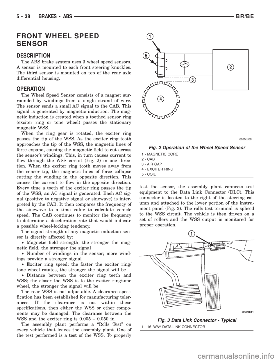
the sensor's windings. This, in turn causes current to
flow through the WSS circuit (Fig. 2) in one direc-
tion. When the exciter ring tooth moves away from
the sensor tip, the magnetic lines of force collapse
cutting the winding in the opposite direction. This
causes the current to flow in the opposite direction.
Every time a tooth of the exciter ring passes the tip
of the WSS, an AC signal is generated. Each AC sig-
nal (positive to negative signal or sinewave) is inter-
preted by the CAB. It then compares the frequency of
the sinewave to a time value to calculate vehicle
speed. The CAB continues to monitor the frequency
to determine a deceleration rate that would indicate
a possible wheel-locking tendency.
The signal strength of any magnetic induction sen-
sor is directly affected by:
²Magnetic field strength; the stronger the mag-
netic field, the stronger the signal
²Number of windings in the sensor; more wind-
ings provide a stronger signal
²Exciter ring speed; the faster the exciter ring/
tone wheel rotates, the stronger the signal will be
²Distance between the exciter ring teeth and
WSS; the closer the WSS is to the exciter ring/tone
wheel, the stronger the signal will be
The rear WSS is not adjustable. A clearance speci-
fication has been established for manufacturing toler-
ances. If the clearance is not within these
specifications, then either the WSS or other compo-
nents may be damaged. The clearance between the
WSS and the exciter ring is 0.005 ± 0.050 in.
The assembly plant performs a ªRolls Testº on
every vehicle that leaves the assembly plant. One of
the test performed is a test of the WSS. To properlytest the sensor, the assembly plant connects test
equipment to the Data Link Connector (DLC). This
connector is located to the right of the steering col-
umn and attached to the lower portion of the instru-
ment panel (Fig. 3). The rolls test terminal is spliced
to the WSS circuit. The vehicle is then driven on a
set of rollers and the WSS output is monitored for
proper operation.
Fig. 2 Operation of the Wheel Speed Sensor
1 - MAGNETIC CORE
2 - CAB
3 - AIR GAP
4 - EXCITER RING
5 - COIL
Fig. 3 Data Link Connector - Typical
1 - 16±WAY DATA LINK CONNECTOR
5 - 38 BRAKES - ABSBR/BE
Page 282 of 2255
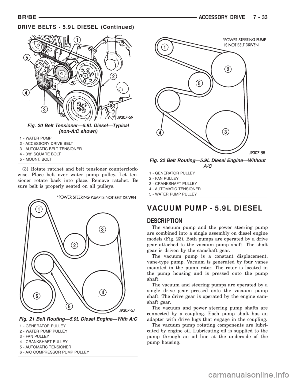
(3) Rotate ratchet and belt tensioner counterclock-
wise. Place belt over water pump pulley. Let ten-
sioner rotate back into place. Remove ratchet. Be
sure belt is properly seated on all pulleys.
VACUUM PUMP - 5.9L DIESEL
DESCRIPTION
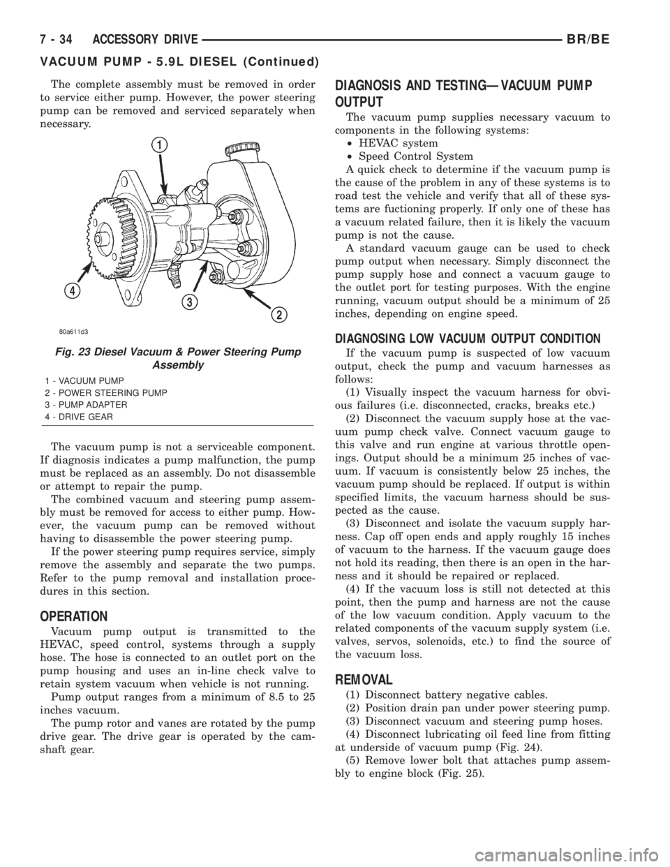
The vacuum pump and the power steering pump
are combined into a single assembly on diesel engine
models (Fig. 23). Both pumps are operated by a drive
gear attached to the vacuum pump shaft. The shaft
gear is driven by the camshaft gear.
The vacuum pump is a constant displacement,
vane-type pump. Vacuum is generated by four vanes
mounted in the pump rotor. The rotor is located in
the pump housing and is pressed onto the pump
shaft.
The vacuum and steering pumps are operated by a
single drive gear pressed onto the vacuum pump
shaft. The drive gear is operated by the engine cam-
shaft gear.
The vacuum and power steering pump shafts are
connected by a coupling. Each pump shaft has an
adapter with drive lugs that engage in the coupling.
The vacuum pump rotating components are lubri-
cated by engine oil. Lubricating oil is supplied to the
pump through an oil line at the underside of the
pump housing.
Fig. 20 Belt TensionerÐ5.9L DieselÐTypical
(non-A/C shown)
1 - WATER PUMP
2 - ACCESSORY DRIVE BELT
3 - AUTOMATIC BELT TENSIONER
4 - 3/89SQUARE BOLT
5 - MOUNT. BOLT
Fig. 21 Belt RoutingÐ5.9L Diesel EngineÐWith A/C
1 - GENERATOR PULLEY
2 - WATER PUMP PULLEY
3 - FAN PULLEY
4 - CRANKSHAFT PULLEY
5 - AUTOMATIC TENSIONER
6 - A/C COMPRESSOR PUMP PULLEY
Fig. 22 Belt RoutingÐ5.9L Diesel EngineÐWithout
A/C
1 - GENERATOR PULLEY
2 - FAN PULLEY
3 - CRANKSHAFT PULLEY
4 - AUTOMATIC TENSIONER
5 - WATER PUMP PULLEY
BR/BEACCESSORY DRIVE 7 - 33
DRIVE BELTS - 5.9L DIESEL (Continued)
Page 283 of 2255
The complete assembly must be removed in order
to service either pump. However, the power steering
pump can be removed and serviced separately when
necessary.
The vacuum pump is not a serviceable component.
If diagnosis indicates a pump malfunction, the pump
must be replaced as an assembly. Do not disassemble
or attempt to repair the pump.
The combined vacuum and steering pump assem-
bly must be removed for access to either pump. How-
ever, the vacuum pump can be removed without
having to disassemble the power steering pump.
If the power steering pump requires service, simply
remove the assembly and separate the two pumps.
Refer to the pump removal and installation proce-
dures in this section.
OPERATION
Vacuum pump output is transmitted to the
HEVAC, speed control, systems through a supply
hose. The hose is connected to an outlet port on the
pump housing and uses an in-line check valve to
retain system vacuum when vehicle is not running.
Pump output ranges from a minimum of 8.5 to 25
inches vacuum.
The pump rotor and vanes are rotated by the pump
drive gear. The drive gear is operated by the cam-
shaft gear.
DIAGNOSIS AND TESTINGÐVACUUM PUMP
OUTPUT
The vacuum pump supplies necessary vacuum to
components in the following systems:
²HEVAC system
²Speed Control System
A quick check to determine if the vacuum pump is
the cause of the problem in any of these systems is to
road test the vehicle and verify that all of these sys-
tems are fuctioning properly. If only one of these has
a vacuum related failure, then it is likely the vacuum
pump is not the cause.
A standard vacuum gauge can be used to check
pump output when necessary. Simply disconnect the
pump supply hose and connect a vacuum gauge to
the outlet port for testing purposes. With the engine
running, vacuum output should be a minimum of 25
inches, depending on engine speed.
DIAGNOSING LOW VACUUM OUTPUT CONDITION
If the vacuum pump is suspected of low vacuum
output, check the pump and vacuum harnesses as
follows:
(1) Visually inspect the vacuum harness for obvi-
ous failures (i.e. disconnected, cracks, breaks etc.)
(2) Disconnect the vacuum supply hose at the vac-
uum pump check valve. Connect vacuum gauge to
this valve and run engine at various throttle open-
ings. Output should be a minimum 25 inches of vac-
uum. If vacuum is consistently below 25 inches, the
vacuum pump should be replaced. If output is within
specified limits, the vacuum harness should be sus-
pected as the cause.
(3) Disconnect and isolate the vacuum supply har-
ness. Cap off open ends and apply roughly 15 inches
of vacuum to the harness. If the vacuum gauge does
not hold its reading, then there is an open in the har-
ness and it should be repaired or replaced.
(4) If the vacuum loss is still not detected at this
point, then the pump and harness are not the cause
of the low vacuum condition. Apply vacuum to the
related components of the vacuum supply system (i.e.
valves, servos, solenoids, etc.) to find the source of
the vacuum loss.
REMOVAL
(1) Disconnect battery negative cables.
(2) Position drain pan under power steering pump.
(3) Disconnect vacuum and steering pump hoses.
(4) Disconnect lubricating oil feed line from fitting
at underside of vacuum pump (Fig. 24).
(5) Remove lower bolt that attaches pump assem-
bly to engine block (Fig. 25).
Fig. 23 Diesel Vacuum & Power Steering Pump
Assembly
1 - VACUUM PUMP
2 - POWER STEERING PUMP
3 - PUMP ADAPTER
4 - DRIVE GEAR
7 - 34 ACCESSORY DRIVEBR/BE
VACUUM PUMP - 5.9L DIESEL (Continued)