check engine DODGE RAM 2003 Service Repair Manual
[x] Cancel search | Manufacturer: DODGE, Model Year: 2003, Model line: RAM, Model: DODGE RAM 2003Pages: 2895, PDF Size: 83.15 MB
Page 2333 of 2895
NOTE: The 45RFE/545RFE utilizes closed loop con-
trol of pump line pressure. The pressure readings
may therefore vary greatly but should always follow
line pressure.
Some common pressures that can be measured to
evaluate pump and clutch performance are the
upshift/downshift pressures, garage shift pressures,
and TCC pressure. The upshift/downshift pressure
for all shifts are shown in UPSHIFT PRESSURES
and DOWNSHIFT PRESSURES. In-gear maximum
pressure for each gear position is shown in IN-GEAR
PRESSURES. The garage shift pressure when per-
forming a N-R shift is 220 psi for 3.7L/4.7L equipped
vehicles and 250 psi for 5.7L equipped vehicles. The
garage shift pressure for the R-N shift is 120 psi. The
garage shift pressure for the N-1 shift is 135 psi for
3.7L/4.7L equipped vehicles and 165 psi for 5.7L
equipped vehicles. Torque converter lock-up pressure
is 120 psi for 3.7L/4.7L equipped vehicles and 125 psi
for 5.7L equipped vehicles.
UPSHIFT PRESSURES
ENGINE 1-2 2-3 2prime-3 3-4 2prime-4 2-5 3-5 4-5
5.7L150 125 125 135 135 135 135 135
3.7L/
4.7L120 120 120 120 120 120 120 130
DOWNSHIFT PRESSURES
ENG-
INE5-4 5-3 5-2 4-34-2
prime3-23-2
prime2
prime
-12-1 3-1
5.7L135 135 135 135 135 135 135 135 135 135
3.7L/
4.7L120 120 120 120 120 120 120 120 120 120
IN-GEAR PRESSURES
ENGINE 1 22
prime345NEUT-
RALREV-
ERSE
5.7L160 135 135 135 135 135 120 250
3.7L/
4.7L135 120 120 120 120 120 120 220
DIAGNOSIS AND TESTING - AIR CHECKING
TRANSMISSION CLUTCH OPERATION
Air-pressure testing can be used to check transmis-
sion clutch operation. The test can be conducted with
the transmission either in the vehicle or on the work
bench, as a final check.
Air-pressure testing requires that the oil pan and
valve body be removed from the transmission. The
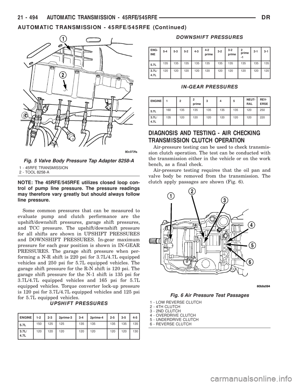
clutch apply passages are shown (Fig. 6).
Fig. 5 Valve Body Pressure Tap Adapter 8258-A
1 - 45RFE TRANSMISSION
2 - TOOL 8258-A
Fig. 6 Air Pressure Test Passages
1 - LOW REVERSE CLUTCH
2 - 4TH CLUTCH
3 - 2ND CLUTCH
4 - OVERDRIVE CLUTCH
5 - UNDERDRIVE CLUTCH
6 - REVERSE CLUTCH
21 - 494 AUTOMATIC TRANSMISSION - 45RFE/545RFEDR
AUTOMATIC TRANSMISSION - 45RFE/545RFE (Continued)
Page 2349 of 2895
(55) Install the manual shift lever from the trans-
mission. Torque the retaining cross-bolt to 16 N´m
(140 in.lbs.).
INSTALLATION
(1) Check torque converter hub and hub drive flats
for sharp edges burrs, scratches, or nicks. Polish the
hub and flats with 320/400 grit paper and crocus
cloth if necessary. Verify that the converter hub
o-ring is properly installed and is free of any debris.
The hub must be smooth to avoid damaging pump
seal at installation.
(2) If a replacement transmission is being
installed, transfer any components necessary, such as
the manual shift lever and shift cable bracket, from
the original transmission onto the replacement trans-
mission.
(3) Lubricate oil pump seal lip with transmission
fluid.
(4) Align converter and oil pump.
(5) Carefully insert converter in oil pump. Then
rotate converter back and forth until fully seated in
pump gears.
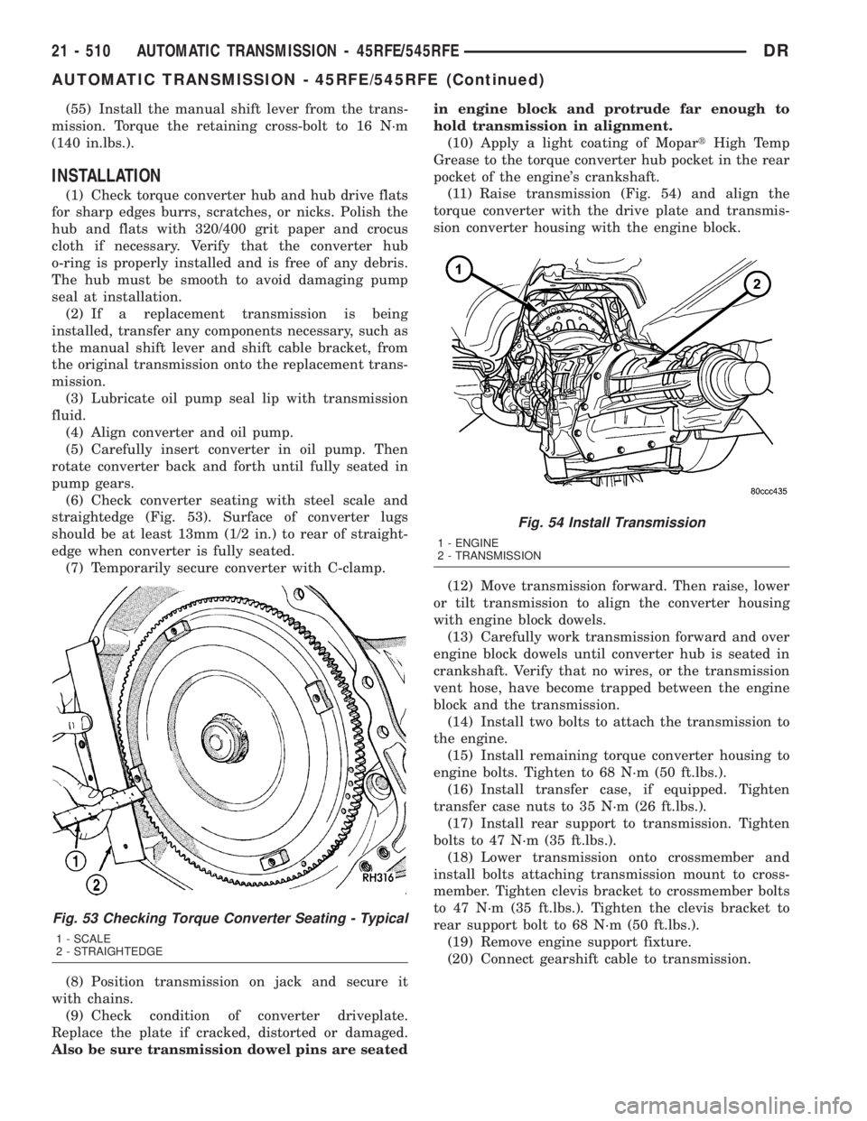
(6) Check converter seating with steel scale and
straightedge (Fig. 53). Surface of converter lugs
should be at least 13mm (1/2 in.) to rear of straight-
edge when converter is fully seated.
(7) Temporarily secure converter with C-clamp.
(8) Position transmission on jack and secure it
with chains.
(9) Check condition of converter driveplate.
Replace the plate if cracked, distorted or damaged.
Also be sure transmission dowel pins are seatedin engine block and protrude far enough to
hold transmission in alignment.
(10) Apply a light coating of MopartHigh Temp
Grease to the torque converter hub pocket in the rear
pocket of the engine's crankshaft.
(11) Raise transmission (Fig. 54) and align the
torque converter with the drive plate and transmis-
sion converter housing with the engine block.
(12) Move transmission forward. Then raise, lower
or tilt transmission to align the converter housing
with engine block dowels.
(13) Carefully work transmission forward and over
engine block dowels until converter hub is seated in
crankshaft. Verify that no wires, or the transmission
vent hose, have become trapped between the engine
block and the transmission.
(14) Install two bolts to attach the transmission to
the engine.
(15) Install remaining torque converter housing to
engine bolts. Tighten to 68 N´m (50 ft.lbs.).
(16) Install transfer case, if equipped. Tighten
transfer case nuts to 35 N´m (26 ft.lbs.).
(17) Install rear support to transmission. Tighten
bolts to 47 N´m (35 ft.lbs.).
(18) Lower transmission onto crossmember and
install bolts attaching transmission mount to cross-
member. Tighten clevis bracket to crossmember bolts
to 47 N´m (35 ft.lbs.). Tighten the clevis bracket to
rear support bolt to 68 N´m (50 ft.lbs.).
(19) Remove engine support fixture.
(20) Connect gearshift cable to transmission.
Fig. 53 Checking Torque Converter Seating - Typical
1 - SCALE
2 - STRAIGHTEDGE
Fig. 54 Install Transmission
1 - ENGINE
2 - TRANSMISSION
21 - 510 AUTOMATIC TRANSMISSION - 45RFE/545RFEDR
AUTOMATIC TRANSMISSION - 45RFE/545RFE (Continued)
Page 2380 of 2895
BTSI FUNCTION CHECK
(1) Verify removal of ignition key allowed in PARK
position only.
(2) When the shift lever is in PARK, the ignition
key cylinder should rotate freely from off to lock.
When the shifter is in any other position, the ignition
key should not rotate from off to lock.
(3) Shifting out of PARK should be possible when
the ignition key cylinder is in the off position.
(4) Shifting out of PARK should not be possible
while applying normal force, and ignition key cylin-
der is in the run or start positions, unless the foot
brake pedal is depressed approximately 1/2 inch
(12mm).
(5) Shifting out of PARK should not be possible
when the ignition key cylinder is in the accessory or
lock position.
(6) Shifting between any gear and NEUTRAL, or
PARK, may be done without depressing foot brake
with ignition switch in run or start positions.
(7) Engine starts must be possible with shifter
lever in PARK or NEUTRAL positions only. Engine
starts must not be possible in any position other than
PARK or NEUTRAL.
(8) With shifter lever in the:
²PARK position - Apply upward force on the shift
arm and remove pressure. Engine starts must be
possible.
²PARK position - Apply downward force on the
shift arm and remove pressure. Engine starts must
be possible.
²NEUTRAL position - Normal position. Engine
starts must be possible.²NEUTRAL position - Engine running and brakes
applied, apply upward force on the shift arm. Trans-
mission shall not be able to shift from neutral to
reverse.
FLUID AND FILTER
DIAGNOSIS AND TESTING
DIAGNOSIS AND TESTING - EFFECTS OF
INCORRECT FLUID LEVEL
A low fluid level allows the pump to take in air
along with the fluid. Air in the fluid will cause fluid
pressures to be low and develop slower than normal.
If the transmission is overfilled, the gears churn the
fluid into foam. This aerates the fluid and causing
the same conditions occurring with a low level. In
either case, air bubbles cause fluid overheating, oxi-
dation and varnish buildup which interferes with
valve and clutch operation. Foaming also causes fluid
expansion which can result in fluid overflow from the
transmission vent or fill tube. Fluid overflow can eas-
ily be mistaken for a leak if inspection is not careful.
DIAGNOSIS AND TESTING - CAUSES OF
BURNT FLUID
Burnt, discolored fluid is a result of overheating
which has three primary causes.
(1) Internal clutch slippage, usually caused by low
line pressure, inadequate clutch apply pressure, or
clutch seal failure.
(2) A result of restricted fluid flow through the
main and/or auxiliary cooler. This condition is usu-
ally the result of a faulty or improperly installed
drainback valve, a damaged main cooler, or severe
restrictions in the coolers and lines caused by debris
or kinked lines.
(3) Heavy duty operation with a vehicle not prop-
erly equipped for this type of operation. Trailer tow-
ing or similar high load operation will overheat the
transmission fluid if the vehicle is improperly
equipped. Such vehicles should have an auxiliary
transmission fluid cooler, a heavy duty cooling sys-
tem, and the engine/axle ratio combination needed to
handle heavy loads.
DIAGNOSIS AND TESTING - FLUID
CONTAMINATION
Transmission fluid contamination is generally a
result of:
²adding incorrect fluid
²failure to clean dipstick and fill tube when
checking level
²engine coolant entering the fluid
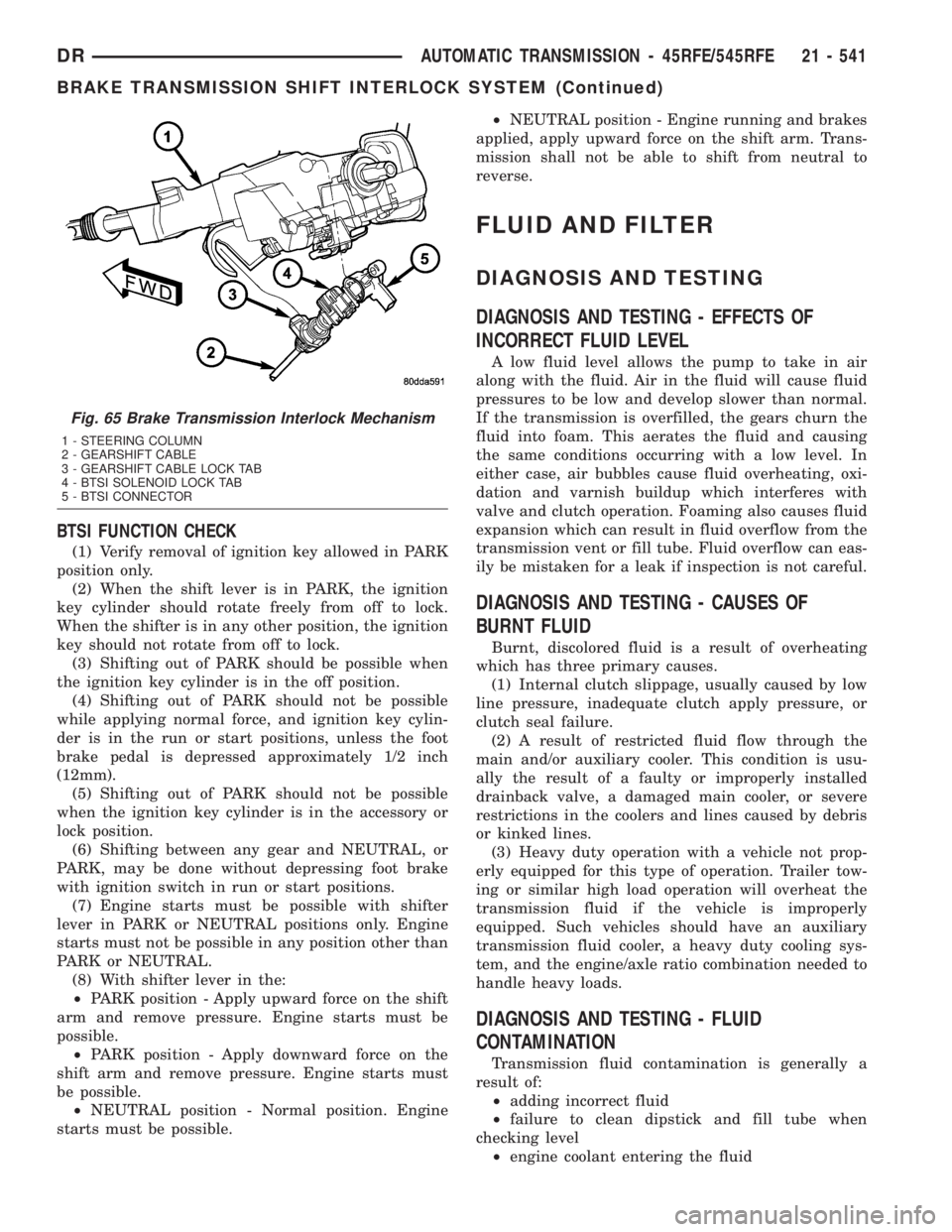
Fig. 65 Brake Transmission Interlock Mechanism
1 - STEERING COLUMN
2 - GEARSHIFT CABLE
3 - GEARSHIFT CABLE LOCK TAB
4 - BTSI SOLENOID LOCK TAB
5 - BTSI CONNECTOR
DRAUTOMATIC TRANSMISSION - 45RFE/545RFE 21 - 541
BRAKE TRANSMISSION SHIFT INTERLOCK SYSTEM (Continued)
Page 2381 of 2895
²internal failure that generates debris
²overheat that generates sludge (fluid break-
down)
²failure to replace contaminated converter after
repair
The use of non-recommended fluids can result in
transmission failure. The usual results are erratic
shifts, slippage, abnormal wear and eventual failure
due to fluid breakdown and sludge formation. Avoid
this condition by using recommended fluids only.
The dipstick cap and fill tube should be wiped
clean before checking fluid level. Dirt, grease and
other foreign material on the cap and tube could fall
into the tube if not removed beforehand. Take the
time to wipe the cap and tube clean before withdraw-
ing the dipstick.
Engine coolant in the transmission fluid is gener-
ally caused by a cooler malfunction. The only remedy
is to replace the radiator as the cooler in the radiator
is not a serviceable part. If coolant has circulated
through the transmission, an overhaul is necessary.
The torque converter should be replaced whenever
a failure generates sludge and debris. This is neces-
sary because normal converter flushing procedures
will not remove all contaminants.
STANDARD PROCEDURE
STANDARD PROCEDURE - FLUID LEVEL
CHECK
Low fluid level can cause a variety of conditions
because it allows the pump to take in air along with
the fluid. As in any hydraulic system, air bubbles
make the fluid spongy, therefore, pressures will be
low and build up slowly.
Improper filling can also raise the fluid level too
high. When the transmssion has too much fluid, the
geartrain churns up foam and cause the same condi-
tions which occur with a low fluid level.
In either case, air bubbles can cause overheating
and/or fluid oxidation, and varnishing. This can
interfere with normal valve, clutch, and accumulator
operation. Foaming can also result in fluid escaping
from the transmission vent where it may be mis-
taken for a leak.
After the fluid has been checked, seat the dipstick
fully to seal out water and dirt.
The transmission has a dipstick to check oil level.
It is located on the right side of the engine. Be sure
to wipe all dirt from dipstick handle before removing.
The torque converter fills in both the P (PARK)
and N (NEUTRAL) positions. Place the selector lever
in P (PARK) to be sure that the fluid level check is
accurate.The engine should be running at idle
speed for at least one minute, with the vehicleon level ground.At normal operating temperature
(approximately 82 C. or 180 F.), the fluid level is cor-
rect if it is in the HOT region (cross-hatched area) on
the oil level indicator. The fluid level will be approx-
imately at the upper COLD hole of the dipstick at
70É F fluid temperature.
NOTE: Engine and Transmission should be at nor-
mal operating temperature before performing this
procedure.
(1) Start engine and apply parking brake.
(2) Shift the transmission into DRIVE for approxi-
mately 2 seconds.
(3) Shift the transmission into REVERSE for
approximately 2 seconds.
(4) Shift the transmission into PARK.
(5) Hook up DRBtscan tool and select transmis-
sion.
(6) Select sensors.
(7) Read the transmission temperature value.
(8) Compare the fluid temperature value with the
chart. (Fig. 66)
(9) Adjust transmission fluid level shown on the
dipstick according to the chart.
NOTE: After adding any fluid to the transmission,
wait a minimum of 2 minutes for the oil to fully
drain from the fill tube into the transmission before
rechecking the fluid level.
(10) Check transmission for leaks.
STANDARD PROCEDURE - FLUID AND FILTER
REPLACEMENT
For proper service intervals (Refer to LUBRICA-
TION & MAINTENANCE/MAINTENANCE SCHED-
ULES - DESCRIPTION).
REMOVAL
(1) Hoist and support vehicle on safety stands.
(2) Place a large diameter shallow drain pan
beneath the transmission pan.
(3) Remove bolts holding front and sides of pan to
transmission.
(4) Loosen bolts holding rear of pan to transmis-
sion.
(5) Slowly separate front of pan away from trans-
mission allowing the fluid to drain into drain pan.
(6) Hold up pan and remove remaining bolts hold-
ing pan to transmission.
(7) While holding pan level, lower pan away from
transmission.
(8) Pour remaining fluid in pan into drain pan.
(9) Remove screw holding filter to valve body (Fig.
67).
21 - 542 AUTOMATIC TRANSMISSION - 45RFE/545RFEDR
FLUID AND FILTER (Continued)
Page 2383 of 2895
(2) Place replacement filter in position on valve
body and into the oil pump.
(3) Install screw to hold filter to valve body (Fig.
67). Tighten screw to 4.5 N´m (40 in. lbs.) torque.
(4) Install new cooler return filter onto the trans-
mission, if necessary. Torque the filter to 14.12 N´m
(125 in.lbs.).
(5) Place bead of MopartRTV sealant onto the
transmission case sealing surface.
(6) Place pan in position on transmission.
(7) Install bolts to hold pan to transmission.
Tighten bolts to 11.8 N´m (105 in. lbs.) torque.
(8) Lower vehicle and fill transmission with
MopartATF +4.
STANDARD PROCEDURE - TRANSMISSION
FILL
To avoid overfilling transmission after a fluid
change or overhaul, perform the following procedure:
(1) Remove dipstick and insert clean funnel in
transmission fill tube.
(2) Add following initial quantity of MopartAT F
+4 to transmission:
(a) If only fluid and filter were changed, add10
pints (5 quarts)of ATF +4 to transmission.
(b) If transmission was completely overhauled
and the torque converter was replaced or drained,
add24 pints (12 quarts)of ATF +4 to transmis-
sion.
(3) Check the transmission fluid (Refer to 21 -
TRANSMISSION/AUTOMATIC - RFE/FLUID -
STANDARD PROCEDURE) and adjust as required.
GEARSHIFT CABLE
DIAGNOSIS AND TESTING - GEARSHIFT
CABLE
(1) Engine starts must be possible with shift lever
in PARK or NEUTRAL positions only. Engine starts
must not be possible in any other gear position.
(2) With the shift lever in the:
(a) PARK position - Apply upward force on the
shift arm and remove pressure. Engine starts must
be possible.
(b) PARK position - Apply downward force on
the shift arm and remove pressure. Engine starts
must be possible.
(c) NEUTRAL position - Normal position. Engine
starts must be possible.
(d) NEUTRAL position - Engine running and
brakes applied, apply upward force on the shift
arm. Transmission shall not be able to shift from
neutral to reverse.
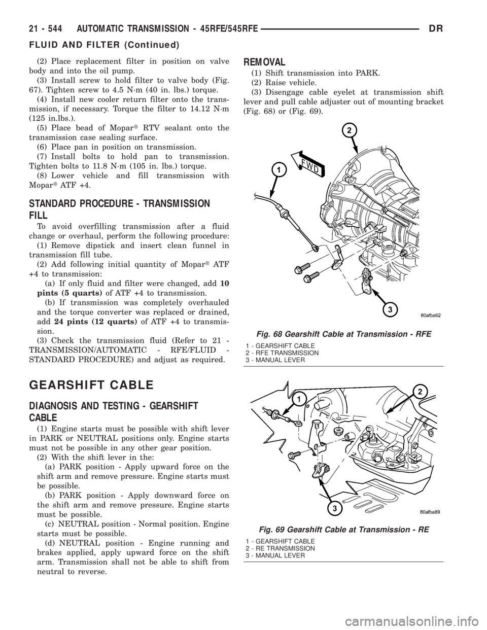
REMOVAL
(1) Shift transmission into PARK.
(2) Raise vehicle.
(3) Disengage cable eyelet at transmission shift
lever and pull cable adjuster out of mounting bracket
(Fig. 68) or (Fig. 69).
Fig. 68 Gearshift Cable at Transmission - RFE
1 - GEARSHIFT CABLE
2 - RFE TRANSMISSION
3 - MANUAL LEVER
Fig. 69 Gearshift Cable at Transmission - RE
1 - GEARSHIFT CABLE
2 - RE TRANSMISSION
3 - MANUAL LEVER
21 - 544 AUTOMATIC TRANSMISSION - 45RFE/545RFEDR
FLUID AND FILTER (Continued)
Page 2385 of 2895
(4) Raise the vehicle.
(5) Place the transmission manual shift lever in
the ªPARKº detent (rearmost) position and rotate
prop shaft to ensure transmission is in PARK.
(6) Route the gearshift cable through the transmis-
sion mounting bracket and secure the cable by snap-
ping the cable retaining ears into the transmission
bracket and snapping the cable eyelet on the manual
shift lever ball stud.
(7) Lower vehicle.
(8) Lock the shift cable adjustment by pressing the
cable adjuster lock tab downward until it snaps into
place.
(9) Check for proper operation of the transmission
range sensor.
(10) Adjust the gearshift cable and BTSI mecha-
nism as necessary.
ADJUSTMENTS
GEARSHIFT CABLE
Check adjustment by starting the engine in PARK
and NEUTRAL. Adjustment is CORRECT if the
engine starts only in these positions. Adjustment is
INCORRECT if the engine starts in one but not both
positions. If the engine starts in any position other
than PARK or NEUTRAL, or if the engine will not
start at all, the transmission range sensor may be
faulty.
Gearshift Adjustment Procedure
(1) Shift transmission into PARK.
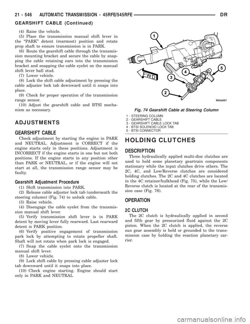
(2) Release cable adjuster lock tab (underneath the
steering column) (Fig. 74) to unlock cable.
(3) Raise vehicle.
(4) Disengage the cable eyelet from the transmis-
sion manual shift lever.
(5) Verify transmission shift lever is in PARK
detent by moving lever fully rearward. Last rearward
detent is PARK position.
(6) Verify positive engagement of transmission
park lock by attempting to rotate propeller shaft.
Shaft will not rotate when park lock is engaged.
(7) Snap the cable eyelet onto the transmission
manual shift lever.
(8) Lower vehicle.
(9) Lock shift cable by pressing cable adjuster lock
tab downward until it snaps into place.
(10) Check engine starting. Engine should start
only in PARK and NEUTRAL
HOLDING CLUTCHES
DESCRIPTION
Three hydraulically applied multi-disc clutches are
used to hold some planetary geartrain components
stationary while the input clutches drive others. The
2C, 4C, and Low/Reverse clutches are considered
holding clutches. The 2C and 4C clutches are located
in the 4C retainer/bulkhead (Fig. 75), while the Low/
Reverse clutch is located at the rear of the transmis-
sion case (Fig. 76).
OPERATION
2C CLUTCH
The 2C clutch is hydraulically applied in second
and fifth gear by pressurized fluid against the 2C
piston. When the 2C clutch is applied, the reverse
sun gear assembly is held or grounded to the trans-
mission case by holding the reaction planetary car-
rier.
Fig. 74 Gearshift Cable at Steering Column
1 - STEERING COLUMN
2 - GEARSHIFT CABLE
3 - GEARSHIFT CABLE LOCK TAB
4 - BTSI SOLENOID LOCK TAB
5 - BTSI CONNECTOR
21 - 546 AUTOMATIC TRANSMISSION - 45RFE/545RFEDR
GEARSHIFT CABLE (Continued)
Page 2402 of 2895
CONVERTER CLUTCH REGULATOR VALVE
The converter clutch regulator valve is used to con-
trol the hydraulic pressure supplied to the back (ON)
side of the torque converter clutch.
TORQUE CONVERTER LIMIT VALVE
The torque converter limit valve serves to limit the
available line pressure to the torque converter clutch.
STANDARD PROCEDURE - OIL PUMP VOLUME
CHECK
Measuring the oil pump output volume will deter-
mine if sufficient oil flow to the transmission oil
cooler exists, and whether or not an internal trans-
mission failure is present.Verify that the transmission fluid is at the proper
level. Refer to the Fluid Level Check procedure in
this section. If necessary, fill the transmission to the
proper level with MopartATF +4, Automatic Trans-
mission Fluid.
(1) Disconnect theTo coolerline at the cooler
inlet and place a collecting container under the dis-
connected line.
CAUTION: With the fluid set at the proper level,
fluid collection should not exceed (1) quart or inter-
nal damage to the transmission may occur.
(2) Run the engineat 1800 rpm, with the shift
selector in neutral. Verify that the transmission fluid
temperature is below 104.5É C (220É F) for this test.
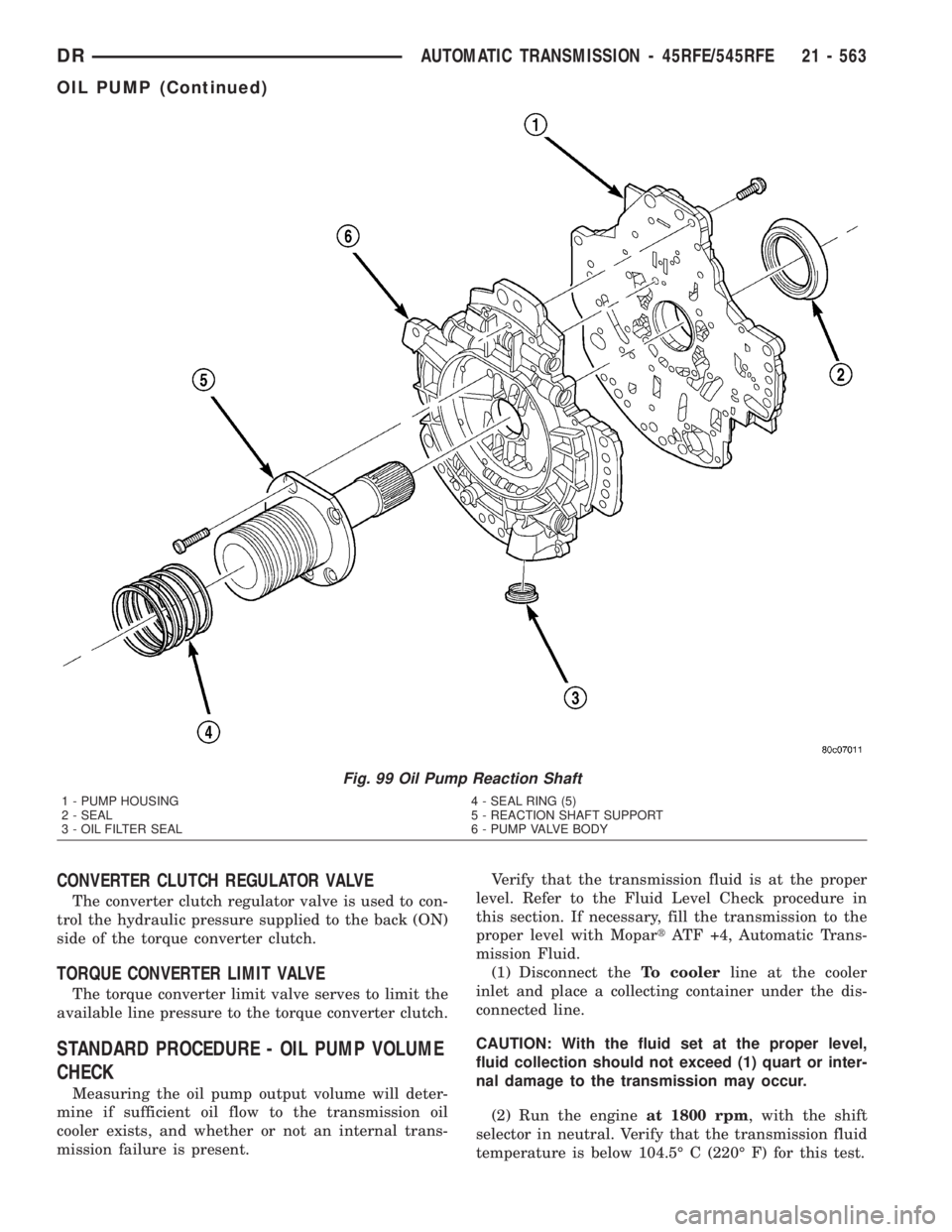
Fig. 99 Oil Pump Reaction Shaft
1 - PUMP HOUSING 4 - SEAL RING (5)
2 - SEAL 5 - REACTION SHAFT SUPPORT
3 - OIL FILTER SEAL 6 - PUMP VALVE BODY
DRAUTOMATIC TRANSMISSION - 45RFE/545RFE 21 - 563
OIL PUMP (Continued)
Page 2419 of 2895
control switch is in the OFF position, the clutch will
engage after the shift to third gear.
The TCM controls the torque converter by way of
internal logic software. The programming of the soft-
ware provides the TCM with control over the L/R-CC
Solenoid. There are four output logic states that can
be applied as follows:
²No EMCC
²Partial EMCC
²Full EMCC
²Gradual-to-no EMCC
NO EMCC
Under No EMCC conditions, the L/R Solenoid is
OFF. There are several conditions that can result in
NO EMCC operations. No EMCC can be initiated
due to a fault in the transmission or because the
TCM does not see the need for EMCC under current
driving conditions.
PARTIAL EMCC
Partial EMCC operation modulates the L/R Sole-
noid (duty cycle) to obtain partial torque converter
clutch application. Partial EMCC operation is main-
tained until Full EMCC is called for and actuated.
During Partial EMCC some slip does occur. Partial
EMCC will usually occur at low speeds, low load and
light throttle situations.
FULL EMCC
During Full EMCC operation, the TCM increases
the L/R Solenoid duty cycle to full ON after Partial
EMCC control brings the engine speed within thedesired slip range of transmission input speed rela-
tive to engine rpm.
GRADUAL-TO-NO EMCC
This operation is to soften the change from Full or
Partial EMCC to No EMCC. This is done at mid-
throttle by decreasing the L/R Solenoid duty cycle.
REMOVAL
(1) Remove transmission and torque converter
from vehicle.
(2) Place a suitable drain pan under the converter
housing end of the transmission.
CAUTION: Verify that transmission is secure on the
lifting device or work surface, the center of gravity
of the transmission will shift when the torque con-
verter is removed creating an unstable condition.
The torque converter is a heavy unit. Use caution
when separating the torque converter from the
transmission.
(3) Pull the torque converter forward until the cen-
ter hub clears the oil pump seal.
(4) Separate the torque converter from the trans-
mission.
INSTALLATION
Check converter hub and drive flats for sharp
edges, burrs, scratches, or nicks. Polish the hub and
flats with 320/400 grit paper or crocus cloth if neces-
sary. Verify that the converter hub o-ring is properly
installed and is free from debris. The hub must be
smooth to avoid damaging the pump seal at installa-
tion.
(1) Lubricate oil pump seal lip with transmission
fluid.
(2) Place torque converter in position on transmis-
sion.
CAUTION: Do not damage oil pump seal or con-
verter hub o-ring while inserting torque converter
into the front of the transmission.
(3) Align torque converter to oil pump seal open-
ing.
(4) Insert torque converter hub into oil pump.
(5) While pushing torque converter inward, rotate
converter until converter is fully seated in the oil
pump gears.
(6) Check converter seating with a scale and
straightedge (Fig. 125). Surface of converter lugs
should be at least 13 mm (1/2 in.) to rear of straight-
edge when converter is fully seated.
(7) If necessary, temporarily secure converter with
C-clamp attached to the converter housing.
(8) Install the transmission in the vehicle.
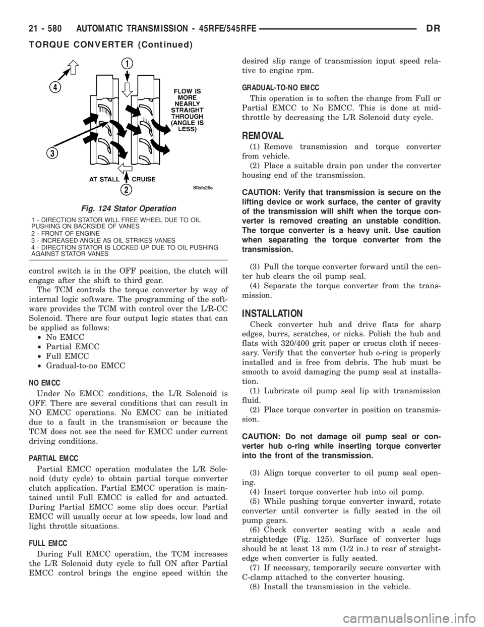
Fig. 124 Stator Operation
1 - DIRECTION STATOR WILL FREE WHEEL DUE TO OIL
PUSHING ON BACKSIDE OF VANES
2 - FRONT OF ENGINE
3 - INCREASED ANGLE AS OIL STRIKES VANES
4 - DIRECTION STATOR IS LOCKED UP DUE TO OIL PUSHING
AGAINST STATOR VANES
21 - 580 AUTOMATIC TRANSMISSION - 45RFE/545RFEDR
TORQUE CONVERTER (Continued)
Page 2423 of 2895
dicted fluid temperature which is calculated from a
combination of inputs:
²Battery (ambient) temperature
²Engine coolant temperature
²In-gear run time since start-up
VALVE BODY
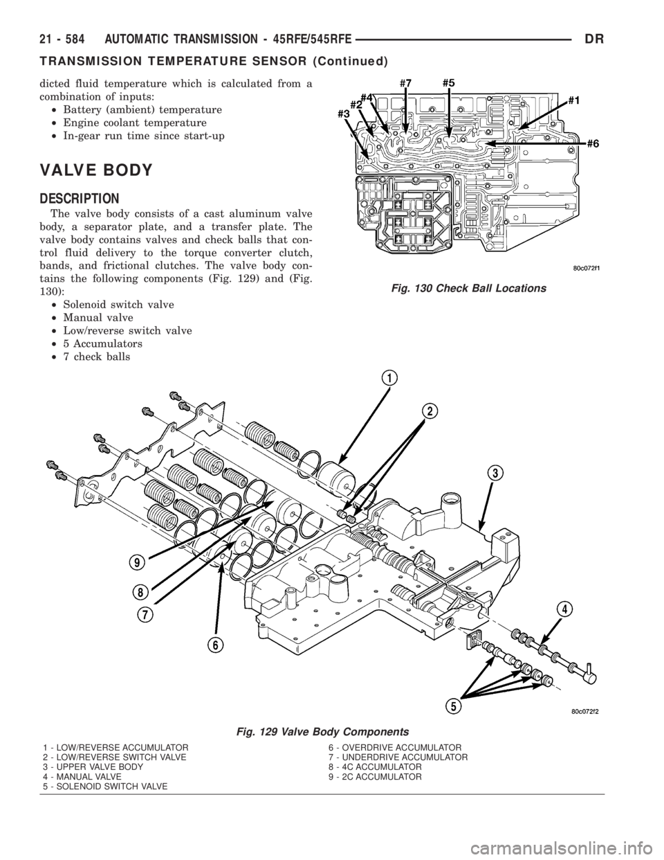
DESCRIPTION
The valve body consists of a cast aluminum valve
body, a separator plate, and a transfer plate. The
valve body contains valves and check balls that con-
trol fluid delivery to the torque converter clutch,
bands, and frictional clutches. The valve body con-
tains the following components (Fig. 129) and (Fig.
130):
²Solenoid switch valve
²Manual valve
²Low/reverse switch valve
²5 Accumulators
²7 check balls
Fig. 129 Valve Body Components
1 - LOW/REVERSE ACCUMULATOR 6 - OVERDRIVE ACCUMULATOR
2 - LOW/REVERSE SWITCH VALVE 7 - UNDERDRIVE ACCUMULATOR
3 - UPPER VALVE BODY 8 - 4C ACCUMULATOR
4 - MANUAL VALVE 9 - 2C ACCUMULATOR
5 - SOLENOID SWITCH VALVE
Fig. 130 Check Ball Locations
21 - 584 AUTOMATIC TRANSMISSION - 45RFE/545RFEDR
TRANSMISSION TEMPERATURE SENSOR (Continued)
Page 2566 of 2895
Owners Manual. A Certification Label on the drivers
side door pillar provides the minimum tire and rim size
for the vehicle. The label also list the cold inflation pres-
sure for these tires at full load operation
Tire pressures have been chosen to provide safe
operation, vehicle stability, and a smooth ride. Tire
pressure should be checked cold once a month. Tire
pressure decreases as the ambient temperature
drops. Check tire pressure frequently when ambient
temperature varies widely.
Tire inflation pressures are cold inflation pressure.
The vehicle must sit for at least 3 hours to obtain the
correct cold inflation pressure reading. Or be driven
less than one mile after sitting for 3 hours. Tire
inflation pressures may increase from 2 to 6 pounds
per square inch (psi) during operation. Do not reduce
this normal pressure build-up.
WARNING: OVER OR UNDER INFLATED TIRES CAN
AFFECT VEHICLE HANDLING AND TREAD WEAR.
THIS MAY CAUSE THE TIRE TO FAIL SUDDENLY,
RESULTING IN LOSS OF VEHICLE CONTROL.
DIAGNOSIS AND TESTING
DIAGNOSIS AND TESTING - PRESSURE
GAUGES
A quality air pressure gauge is recommended to
check tire pressure. After checking the air pressure,
replace valve cap finger tight.
DIAGNOSIS AND TESTING - TIRE NOISE OR
VIBRATION
Radial-ply tires are sensitive to force impulses
caused by improper mounting, vibration, wheel
defects, or possibly tire imbalance.
To find out if tires are causing the noise or vibra-
tion, drive the vehicle over a smooth road at varying
speeds. Note the noise level during acceleration and
deceleration. The engine, differential and exhaust
noises will change as speed varies, while the tire
noise will usually remain constant.
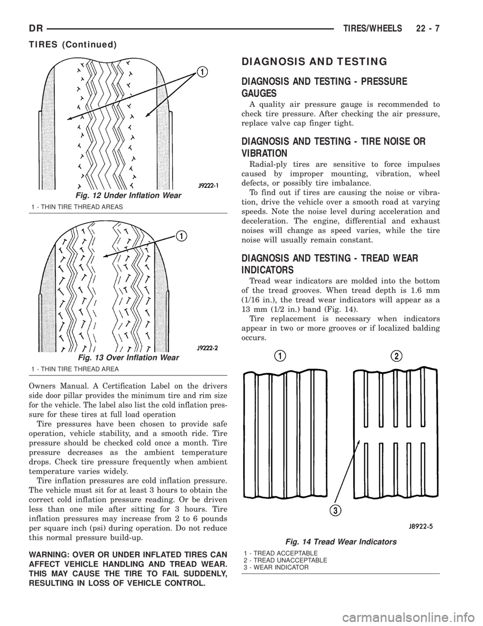
DIAGNOSIS AND TESTING - TREAD WEAR
INDICATORS
Tread wear indicators are molded into the bottom
of the tread grooves. When tread depth is 1.6 mm
(1/16 in.), the tread wear indicators will appear as a
13 mm (1/2 in.) band (Fig. 14).
Tire replacement is necessary when indicators
appear in two or more grooves or if localized balding
occurs.
Fig. 12 Under Inflation Wear
1 - THIN TIRE THREAD AREAS
Fig. 13 Over Inflation Wear
1 - THIN TIRE THREAD AREA
Fig. 14 Tread Wear Indicators
1 - TREAD ACCEPTABLE
2 - TREAD UNACCEPTABLE
3 - WEAR INDICATOR
DRTIRES/WHEELS 22 - 7
TIRES (Continued)