check engine DODGE RAM 2003 Service Manual PDF
[x] Cancel search | Manufacturer: DODGE, Model Year: 2003, Model line: RAM, Model: DODGE RAM 2003Pages: 2895, PDF Size: 83.15 MB
Page 351 of 2895
water pump while removing pump from vehicle. Do
not remove the clamp from the bypass hose.
(9) Discard the old gasket.
CAUTION: Do not pry the water pump at timing
chain case/cover. The machined surfaces may be
damaged resulting in leaks.
CLEANING
Clean gasket mating surfaces as necessary.
INSPECTION
Visually inspect the water pump and replace if it
has any of the following conditions:
²The body is cracked or damaged
²Water leaks from the shaft seal. This is evident
by traces of coolant below the vent hole
²Loose or rough turning bearing.
²Impeller rubbing the pump body
INSTALLATION
(1) Clean the gasket mating surfaces.
(2) Using a new gasket, install the water pump to
the engine as follows: Guide the water pump tube
into the bypass hose as the pump is being installed.
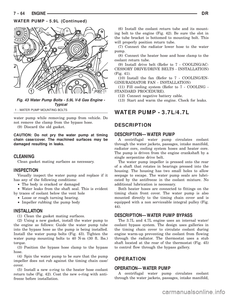
Install the water pump bolts (Fig. 43). Tighten the
water pump mounting bolts to 40 N´m (30 ft. lbs.)
torque.
(3) Position the bypass hose clamp to the bypass
hose.
(4) Spin the water pump to be sure that the pump
impeller does not rub against the timing chain case/
cover.
(5) Install a new o-ring to the heater hose coolant
return tube (Fig. 42). Coat the new o-ring with anti-
freeze before installation.(6) Install the coolant return tube and its mount-
ing bolt to the engine (Fig. 42). Be sure the slot in
the tube bracket is bottomed to mounting bolt. This
will properly position return tube.
(7) Connect the radiator lower hose to the water
pump.
(8) Connect the heater hose and hose clamp to the
coolant return tube.
(9) Install drive belt (Refer to 7 - COOLING/AC-
CESSORY DRIVE/DRIVE BELTS - INSTALLATION)
(Fig. 41).
(10) Install the fan (Refer to 7 - COOLING/EN-
GINE/RADIATOR FAN - INSTALLATION)
(11) Fill cooling system (Refer to 7 - COOLING -
STANDARD PROCEDURE).
(12) Connect negative battery cable.
(13) Start and warm the engine. Check for leaks.
WATER PUMP - 3.7L/4.7L
DESCRIPTION
DESCRIPTIONÐWATER PUMP
A centrifugal water pump circulates coolant
through the water jackets, passages, intake manifold,
radiator core, cooling system hoses and heater core.
The pump is driven from the engine crankshaft by a
single serpentine drive belt.
The water pump impeller is pressed onto the rear
of a shaft that rotates in bearings pressed into the
housing. The housing has two small holes to allow
seepage to escape. The water pump seals are lubri-
cated by the antifreeze in the coolant mixture. No
additional lubrication is necessary.
Both heater hoses are connected to fittings on the
timing chain front cover. The water pump is also
mounted directly to the timing chain cover and is
equipped with a non serviceable integral pulley (Fig.
44).
DESCRIPTIONÐWATER PUMP BYPASS
The 3.7L and 4.7L engine uses an internal water/
coolant bypass system. The design uses galleries in
the timing chain cover to circulate coolant during
engine warm-up preventing the coolant from flowing
through the radiator. The thermostat uses a stub
shaft located at the rear of the thermostat (Fig. 45)
to control flow through the bypass gallery.
OPERATION
OPERATIONÐWATER PUMP
A centrifugal water pump circulates coolant
through the water jackets, passages, intake manifold,
Fig. 43 Water Pump Bolts - 5.9L V-8 Gas Engine -
Typical
1 - WATER PUMP MOUNTING BOLTS
7 - 64 ENGINEDR
WATER PUMP - 5.9L (Continued)
Page 354 of 2895
CAUTION: When installing the serpentine accessory
drive belt, the belt must be routed correctly. If not,
the engine may overheat due to the water pump
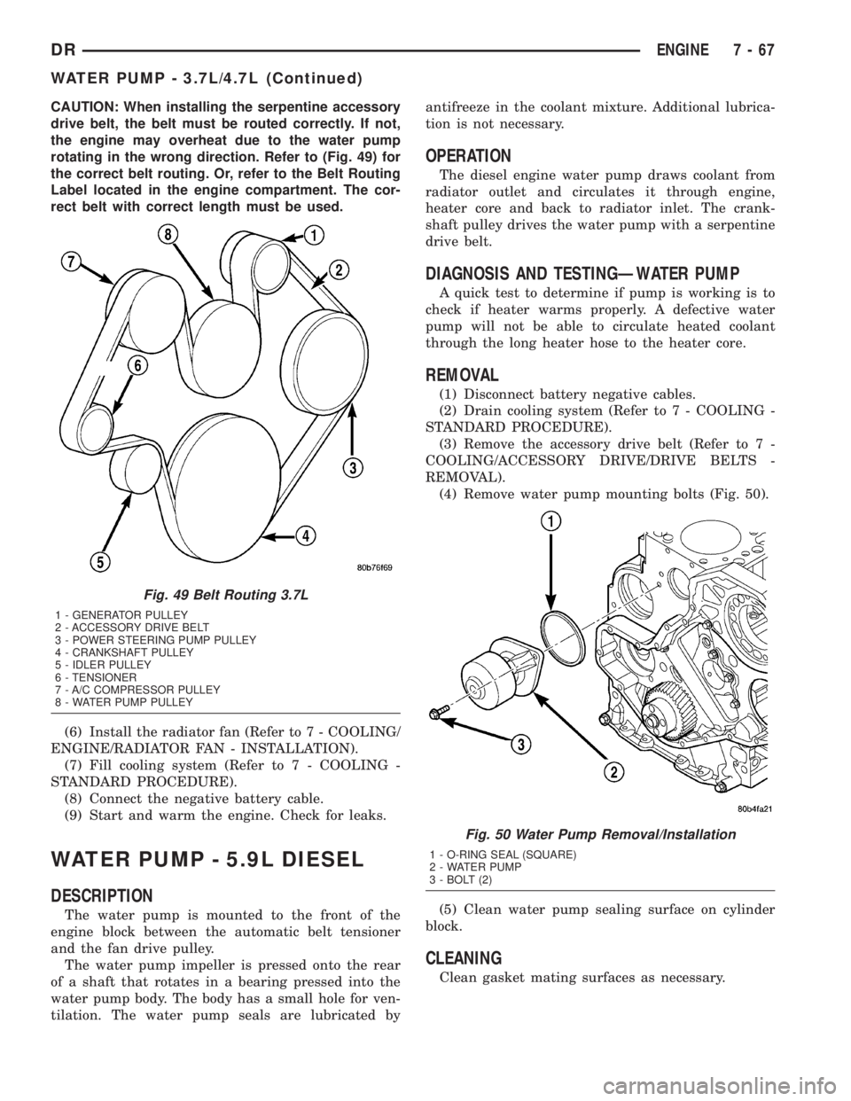
rotating in the wrong direction. Refer to (Fig. 49) for
the correct belt routing. Or, refer to the Belt Routing
Label located in the engine compartment. The cor-
rect belt with correct length must be used.
(6) Install the radiator fan (Refer to 7 - COOLING/
ENGINE/RADIATOR FAN - INSTALLATION).
(7) Fill cooling system (Refer to 7 - COOLING -
STANDARD PROCEDURE).
(8) Connect the negative battery cable.
(9) Start and warm the engine. Check for leaks.
WATER PUMP - 5.9L DIESEL
DESCRIPTION
The water pump is mounted to the front of the
engine block between the automatic belt tensioner
and the fan drive pulley.
The water pump impeller is pressed onto the rear
of a shaft that rotates in a bearing pressed into the
water pump body. The body has a small hole for ven-
tilation. The water pump seals are lubricated byantifreeze in the coolant mixture. Additional lubrica-
tion is not necessary.
OPERATION
The diesel engine water pump draws coolant from
radiator outlet and circulates it through engine,
heater core and back to radiator inlet. The crank-
shaft pulley drives the water pump with a serpentine
drive belt.
DIAGNOSIS AND TESTINGÐWATER PUMP
A quick test to determine if pump is working is to
check if heater warms properly. A defective water
pump will not be able to circulate heated coolant
through the long heater hose to the heater core.
REMOVAL
(1) Disconnect battery negative cables.
(2) Drain cooling system (Refer to 7 - COOLING -
STANDARD PROCEDURE).
(3) Remove the accessory drive belt (Refer to 7 -
COOLING/ACCESSORY DRIVE/DRIVE BELTS -
REMOVAL).
(4) Remove water pump mounting bolts (Fig. 50).
(5) Clean water pump sealing surface on cylinder
block.
CLEANING
Clean gasket mating surfaces as necessary.
Fig. 49 Belt Routing 3.7L
1 - GENERATOR PULLEY
2 - ACCESSORY DRIVE BELT
3 - POWER STEERING PUMP PULLEY
4 - CRANKSHAFT PULLEY
5 - IDLER PULLEY
6 - TENSIONER
7 - A/C COMPRESSOR PULLEY
8 - WATER PUMP PULLEY
Fig. 50 Water Pump Removal/Installation
1 - O-RING SEAL (SQUARE)
2 - WATER PUMP
3 - BOLT (2)
DRENGINE 7 - 67
WATER PUMP - 3.7L/4.7L (Continued)
Page 355 of 2895
INSPECTION
Visually inspect the water pump and replace if it
has any of the following conditions:
²The body is cracked or damaged
²Water leaks from the shaft seal. This is evident
by traces of coolant below the vent hole
²Loose or rough turning bearing.
²Impeller rubbing the pump body
INSTALLATION
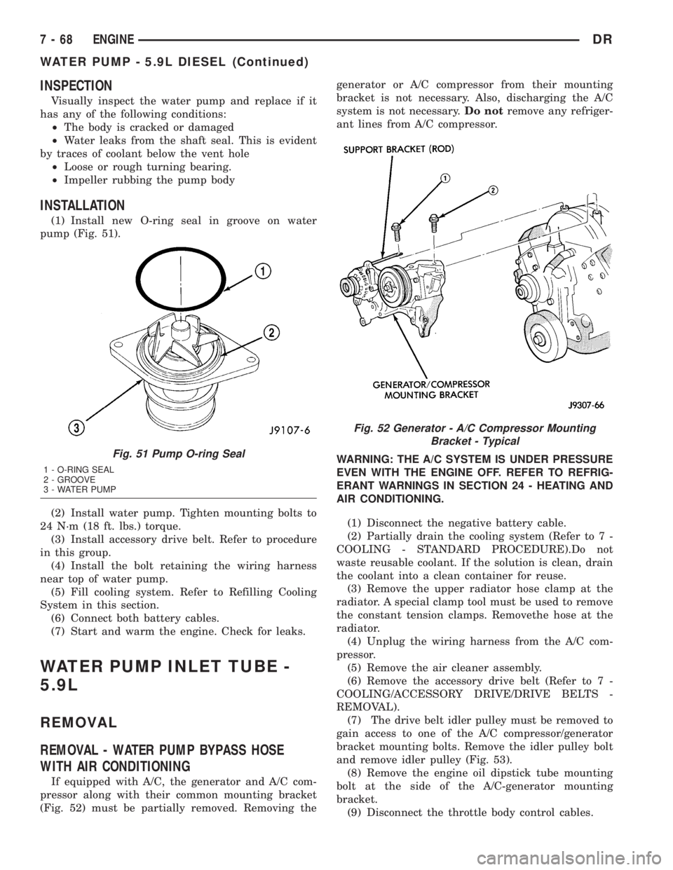
(1) Install new O-ring seal in groove on water
pump (Fig. 51).
(2) Install water pump. Tighten mounting bolts to
24 N´m (18 ft. lbs.) torque.
(3) Install accessory drive belt. Refer to procedure
in this group.
(4) Install the bolt retaining the wiring harness
near top of water pump.
(5) Fill cooling system. Refer to Refilling Cooling
System in this section.
(6) Connect both battery cables.
(7) Start and warm the engine. Check for leaks.
WATER PUMP INLET TUBE -
5.9L
REMOVAL
REMOVAL - WATER PUMP BYPASS HOSE
WITH AIR CONDITIONING
If equipped with A/C, the generator and A/C com-
pressor along with their common mounting bracket
(Fig. 52) must be partially removed. Removing thegenerator or A/C compressor from their mounting
bracket is not necessary. Also, discharging the A/C
system is not necessary.Do notremove any refriger-
ant lines from A/C compressor.
WARNING: THE A/C SYSTEM IS UNDER PRESSURE
EVEN WITH THE ENGINE OFF. REFER TO REFRIG-
ERANT WARNINGS IN SECTION 24 - HEATING AND
AIR CONDITIONING.
(1) Disconnect the negative battery cable.
(2) Partially drain the cooling system (Refer to 7 -
COOLING - STANDARD PROCEDURE).Do not
waste reusable coolant. If the solution is clean, drain
the coolant into a clean container for reuse.
(3) Remove the upper radiator hose clamp at the
radiator. A special clamp tool must be used to remove
the constant tension clamps. Removethe hose at the
radiator.
(4) Unplug the wiring harness from the A/C com-
pressor.
(5) Remove the air cleaner assembly.
(6) Remove the accessory drive belt (Refer to 7 -
COOLING/ACCESSORY DRIVE/DRIVE BELTS -
REMOVAL).
(7) The drive belt idler pulley must be removed to
gain access to one of the A/C compressor/generator
bracket mounting bolts. Remove the idler pulley bolt
and remove idler pulley (Fig. 53).
(8) Remove the engine oil dipstick tube mounting
bolt at the side of the A/C-generator mounting
bracket.
(9) Disconnect the throttle body control cables.
Fig. 51 Pump O-ring Seal
1 - O-RING SEAL
2 - GROOVE
3 - WATER PUMP
Fig. 52 Generator - A/C Compressor Mounting
Bracket - Typical
7 - 68 ENGINEDR
WATER PUMP - 5.9L DIESEL (Continued)
Page 357 of 2895
CAUTION: A number or letter is stamped into the
tongue of the constant tension clamps. If replace-
ment is necessary, use only an original equipment
clamp with a matching number or letter and width.
(2) Loosen both of the bypass hose clamps and
position them to the center of the hose.
(3) Removethe hose from the vehicle.
INSTALLATION
INSTALLATION - WATER PUMP BYPASS HOSE
WITH AIR CONDITIONING
(1) Position the bypass hose clamps to the center
of the bypass hose.
(2) Install the bypass hose to the engine.
(3) Secure both of the hose clamps.
(4) Install the generator-A/C mounting bracket
assembly to the engine. Tighten bolt number 1 (Fig.
53) to 41 N´m (30 ft. lbs.). Tighten bolt number 2
(Fig. 53) to 28 N´m (20 ft. lbs.). Tighten bracket
mounting bolts (Fig. 53) (Fig. 53) to 40 N´m (30 ft.
lbs.).
(5) Install a new O-ring to the heater hose coolant
return tube. Coat the new O-ring with antifreeze
before installation.
(6) Install the coolant return tube and its mount-
ing bolt to the engine.
(7) Connect the throttle body control cables.
(8) Install the oil dipstick mounting bolt.
(9) Install the idler pulley. Tighten the bolt to 41
N´m (30 ft. lbs.) (Fig. 57).
(10) Install the drive belt (Refer to 7 - COOLING/
ACCESSORY DRIVE/DRIVE BELTS - INSTALLA-
TION).CAUTION: When installing the serpentine accessory
drive belt, the belt must be routed correctly. If not,
the engine may overheat due to the water pump
rotating in the wrong direction (Refer to 7 - COOL-
ING/ACCESSORY DRIVE/DRIVE BELTS - INSTALLA-
TION). The correct belt with the correct length must
be used.
(11) Install the air cleaner assembly.
(12) Install the upper radiator hose to the radiator.
(13) Connect the throttle cable to the clip at the
radiator fan shroud.
(14) Connect the wiring harness to the A/C com-
pressor.
(15) Fill the cooling system (Refer to 7 - COOLING
- STANDARD PROCEDURE).
(16) Start and warm the engine. Check for leaks.
INSTALLATION - WATER PUMP BYPASS HOSE
WITHOUT AIR CONDITIONING
(1) Position the bypass hose clamps to the center
of the bypass hose.
(2) Install the bypass hose tothe engine.
(3) Secure both of the hose clamps.
(4) Fill the cooling system (Refer to 7 - COOLING
- STANDARD PROCEDURE).
(5) Start and warm the engine. Check for leaks.
WATER PUMP - 5.7L
REMOVAL
(1) Disconnect negative battery cable.
(2) Drain coolant.
(3) Remove serpentine belt.
(4) Remove fan clutch assembly.
(5) Remove coolant fill bottle.
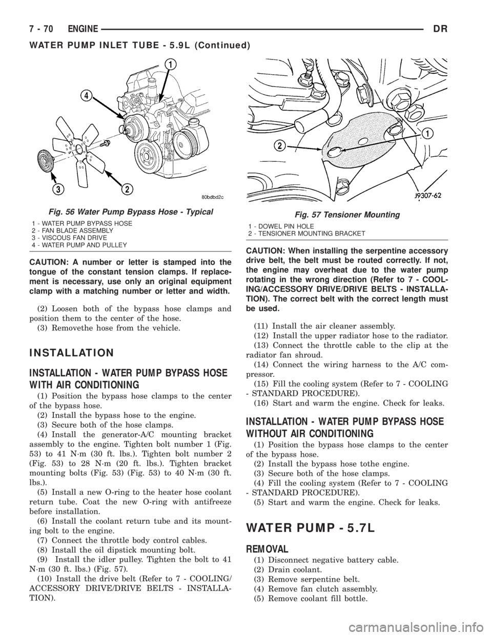
Fig. 56 Water Pump Bypass Hose - Typical
1 - WATER PUMP BYPASS HOSE
2 - FAN BLADE ASSEMBLY
3 - VISCOUS FAN DRIVE
4 - WATER PUMP AND PULLEY
Fig. 57 Tensioner Mounting
1 - DOWEL PIN HOLE
2 - TENSIONER MOUNTING BRACKET
7 - 70 ENGINEDR
WATER PUMP INLET TUBE - 5.9L (Continued)
Page 360 of 2895
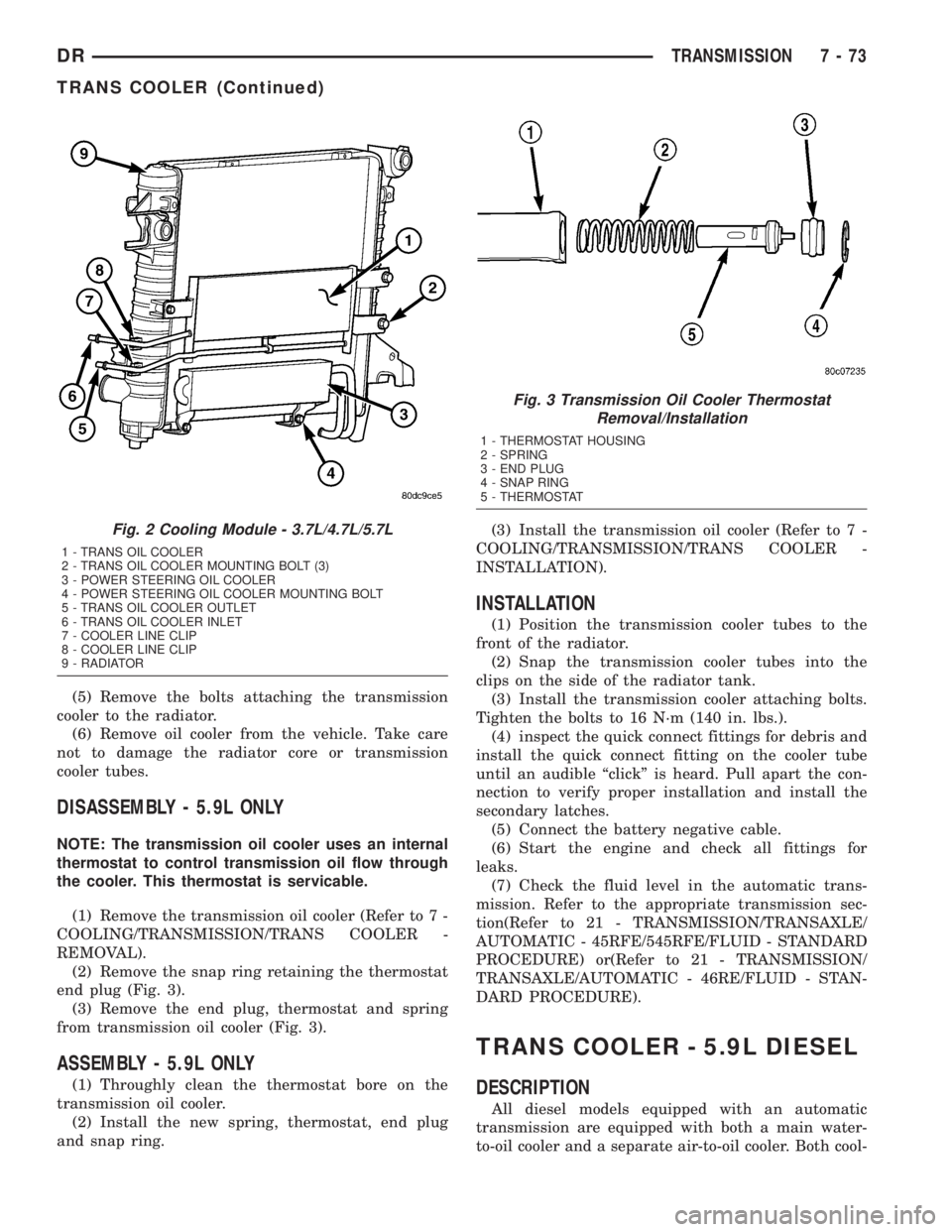
(5) Remove the bolts attaching the transmission
cooler to the radiator.
(6) Remove oil cooler from the vehicle. Take care
not to damage the radiator core or transmission
cooler tubes.
DISASSEMBLY - 5.9L ONLY
NOTE: The transmission oil cooler uses an internal
thermostat to control transmission oil flow through
the cooler. This thermostat is servicable.
(1) Remove the transmission oil cooler (Refer to 7 -
COOLING/TRANSMISSION/TRANS COOLER -
REMOVAL).
(2) Remove the snap ring retaining the thermostat
end plug (Fig. 3).
(3) Remove the end plug, thermostat and spring
from transmission oil cooler (Fig. 3).
ASSEMBLY - 5.9L ONLY
(1) Throughly clean the thermostat bore on the
transmission oil cooler.
(2) Install the new spring, thermostat, end plug
and snap ring.(3) Install the transmission oil cooler (Refer to 7 -
COOLING/TRANSMISSION/TRANS COOLER -
INSTALLATION).
INSTALLATION
(1) Position the transmission cooler tubes to the
front of the radiator.
(2) Snap the transmission cooler tubes into the
clips on the side of the radiator tank.
(3) Install the transmission cooler attaching bolts.
Tighten the bolts to 16 N´m (140 in. lbs.).
(4) inspect the quick connect fittings for debris and
install the quick connect fitting on the cooler tube
until an audible ªclickº is heard. Pull apart the con-
nection to verify proper installation and install the
secondary latches.
(5) Connect the battery negative cable.
(6) Start the engine and check all fittings for
leaks.
(7) Check the fluid level in the automatic trans-
mission. Refer to the appropriate transmission sec-
tion(Refer to 21 - TRANSMISSION/TRANSAXLE/
AUTOMATIC - 45RFE/545RFE/FLUID - STANDARD
PROCEDURE) or(Refer to 21 - TRANSMISSION/
TRANSAXLE/AUTOMATIC - 46RE/FLUID - STAN-
DARD PROCEDURE).
TRANS COOLER - 5.9L DIESEL
DESCRIPTION
All diesel models equipped with an automatic
transmission are equipped with both a main water-
to-oil cooler and a separate air-to-oil cooler. Both cool-
Fig. 2 Cooling Module - 3.7L/4.7L/5.7L
1 - TRANS OIL COOLER
2 - TRANS OIL COOLER MOUNTING BOLT (3)
3 - POWER STEERING OIL COOLER
4 - POWER STEERING OIL COOLER MOUNTING BOLT
5 - TRANS OIL COOLER OUTLET
6 - TRANS OIL COOLER INLET
7 - COOLER LINE CLIP
8 - COOLER LINE CLIP
9 - RADIATOR
Fig. 3 Transmission Oil Cooler Thermostat
Removal/Installation
1 - THERMOSTAT HOUSING
2 - SPRING
3 - END PLUG
4 - SNAP RING
5 - THERMOSTAT
DRTRANSMISSION 7 - 73
TRANS COOLER (Continued)
Page 362 of 2895
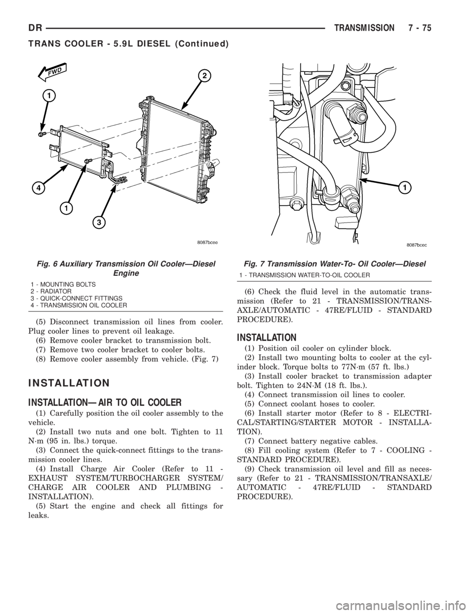
(5) Disconnect transmission oil lines from cooler.
Plug cooler lines to prevent oil leakage.
(6) Remove cooler bracket to transmission bolt.
(7) Remove two cooler bracket to cooler bolts.
(8) Remove cooler assembly from vehicle. (Fig. 7)
INSTALLATION
INSTALLATIONÐAIR TO OIL COOLER
(1) Carefully position the oil cooler assembly to the
vehicle.
(2) Install two nuts and one bolt. Tighten to 11
N´m (95 in. lbs.) torque.
(3) Connect the quick-connect fittings to the trans-
mission cooler lines.
(4) Install Charge Air Cooler (Refer to 11 -
EXHAUST SYSTEM/TURBOCHARGER SYSTEM/
CHARGE AIR COOLER AND PLUMBING -
INSTALLATION).
(5) Start the engine and check all fittings for
leaks.(6) Check the fluid level in the automatic trans-
mission (Refer to 21 - TRANSMISSION/TRANS-
AXLE/AUTOMATIC - 47RE/FLUID - STANDARD
PROCEDURE).
INSTALLATION
(1) Position oil cooler on cylinder block.
(2) Install two mounting bolts to cooler at the cyl-
inder block. Torque bolts to 77N´m (57 ft. lbs.)
(3) Install cooler bracket to transmission adapter
bolt. Tighten to 24N´M (18 ft. lbs.).
(4) Connect transmission oil lines to cooler.
(5) Connect coolant hoses to cooler.
(6) Install starter motor (Refer to 8 - ELECTRI-
CAL/STARTING/STARTER MOTOR - INSTALLA-
TION).
(7) Connect battery negative cables.
(8) Fill cooling system (Refer to 7 - COOLING -
STANDARD PROCEDURE).
(9) Check transmission oil level and fill as neces-
sary (Refer to 21 - TRANSMISSION/TRANSAXLE/
AUTOMATIC - 47RE/FLUID - STANDARD
PROCEDURE).
Fig. 6 Auxiliary Transmission Oil CoolerÐDiesel
Engine
1 - MOUNTING BOLTS
2 - RADIATOR
3 - QUICK-CONNECT FITTINGS
4 - TRANSMISSION OIL COOLER
Fig. 7 Transmission Water-To- Oil CoolerÐDiesel
1 - TRANSMISSION WATER-TO-OIL COOLER
DRTRANSMISSION 7 - 75
TRANS COOLER - 5.9L DIESEL (Continued)
Page 368 of 2895
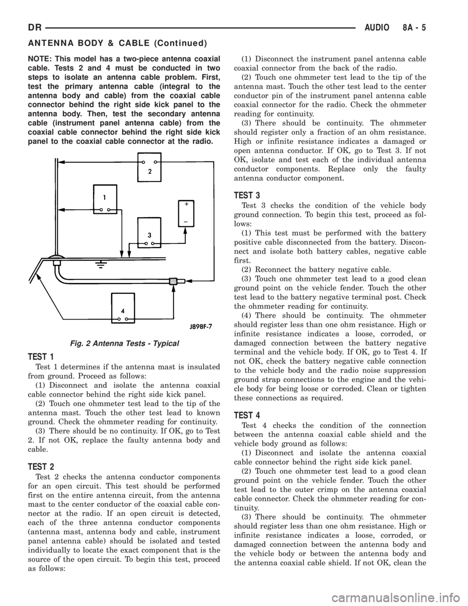
NOTE: This model has a two-piece antenna coaxial
cable. Tests 2 and 4 must be conducted in two
steps to isolate an antenna cable problem. First,
test the primary antenna cable (integral to the
antenna body and cable) from the coaxial cable
connector behind the right side kick panel to the
antenna body. Then, test the secondary antenna
cable (instrument panel antenna cable) from the
coaxial cable connector behind the right side kick
panel to the coaxial cable connector at the radio.
TEST 1
Test 1 determines if the antenna mast is insulated
from ground. Proceed as follows:
(1) Disconnect and isolate the antenna coaxial
cable connector behind the right side kick panel.
(2) Touch one ohmmeter test lead to the tip of the
antenna mast. Touch the other test lead to known
ground. Check the ohmmeter reading for continuity.
(3) There should be no continuity. If OK, go to Test
2. If not OK, replace the faulty antenna body and
cable.
TEST 2
Test 2 checks the antenna conductor components
for an open circuit. This test should be performed
first on the entire antenna circuit, from the antenna
mast to the center conductor of the coaxial cable con-
nector at the radio. If an open circuit is detected,
each of the three antenna conductor components
(antenna mast, antenna body and cable, instrument
panel antenna cable) should be isolated and tested
individually to locate the exact component that is the
source of the open circuit. To begin this test, proceed
as follows:(1) Disconnect the instrument panel antenna cable
coaxial connector from the back of the radio.
(2) Touch one ohmmeter test lead to the tip of the
antenna mast. Touch the other test lead to the center
conductor pin of the instrument panel antenna cable
coaxial connector for the radio. Check the ohmmeter
reading for continuity.
(3) There should be continuity. The ohmmeter
should register only a fraction of an ohm resistance.
High or infinite resistance indicates a damaged or
open antenna conductor. If OK, go to Test 3. If not
OK, isolate and test each of the individual antenna
conductor components. Replace only the faulty
antenna conductor component.
TEST 3
Test 3 checks the condition of the vehicle body
ground connection. To begin this test, proceed as fol-
lows:
(1) This test must be performed with the battery
positive cable disconnected from the battery. Discon-
nect and isolate both battery cables, negative cable
first.
(2) Reconnect the battery negative cable.
(3) Touch one ohmmeter test lead to a good clean
ground point on the vehicle fender. Touch the other
test lead to the battery negative terminal post. Check
the ohmmeter reading for continuity.
(4) There should be continuity. The ohmmeter
should register less than one ohm resistance. High or
infinite resistance indicates a loose, corroded, or
damaged connection between the battery negative
terminal and the vehicle body. If OK, go to Test 4. If
not OK, check the battery negative cable connection
to the vehicle body and the radio noise suppression
ground strap connections to the engine and the vehi-
cle body for being loose or corroded. Clean or tighten
these connections as required.
TEST 4
Test 4 checks the condition of the connection
between the antenna coaxial cable shield and the
vehicle body ground as follows:
(1) Disconnect and isolate the antenna coaxial
cable connector behind the right side kick panel.
(2) Touch one ohmmeter test lead to a good clean
ground point on the vehicle fender. Touch the other
test lead to the outer crimp on the antenna coaxial
cable connector. Check the ohmmeter reading for con-
tinuity.
(3) There should be continuity. The ohmmeter
should register less than one ohm resistance. High or
infinite resistance indicates a loose, corroded, or
damaged connection between the antenna body and
the vehicle body or between the antenna body and
the antenna coaxial cable shield. If not OK, clean the
Fig. 2 Antenna Tests - Typical
DRAUDIO 8A - 5
ANTENNA BODY & CABLE (Continued)
Page 385 of 2895
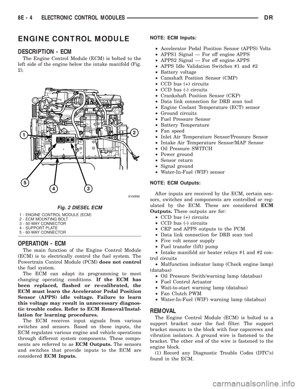
ENGINE CONTROL MODULE
DESCRIPTION - ECM
The Engine Control Module (ECM) is bolted to the
left side of the engine below the intake manifold (Fig.
2).
OPERATION - ECM
The main function of the Engine Control Module
(ECM) is to electrically control the fuel system. The
Powertrain Control Module (PCM)does not control
the fuel system.
The ECM can adapt its programming to meet
changing operating conditions.If the ECM has
been replaced, flashed or re-calibrated, the
ECM must learn the Accelerator Pedal Position
Sensor (APPS) idle voltage. Failure to learn
this voltage may result in unnecessary diagnos-
tic trouble codes. Refer to ECM Removal/Instal-
lation for learning procedures.
The ECM receives input signals from various
switches and sensors. Based on these inputs, the
ECM regulates various engine and vehicle operations
through different system components. These compo-
nents are referred to asECM Outputs.The sensors
and switches that provide inputs to the ECM are
consideredECM Inputs.NOTE: ECM Inputs:
²Accelerator Pedal Position Sensor (APPS) Volts
²APPS1 Signal Ð For off engine APPS
²APPS2 Signal Ð For off engine APPS
²APPS Idle Validation Switches #1 and #2
²Battery voltage
²Camshaft Position Sensor (CMP)
²CCD bus (+) circuits
²CCD bus (-) circuits
²Crankshaft Position Sensor (CKP)
²Data link connection for DRB scan tool
²Engine Coolant Temperature (ECT) sensor
²Ground circuits
²Fuel Pressure Sensor
²Battery Temperature
²Fan speed
²Inlet Air Temperature Sensor/Pressure Sensor
²Intake Air Temperature Sensor/MAP Sensor
²Oil Pressure SWITCH
²Power ground
²Sensor return
²Signal ground
²Water-In-Fuel (WIF) sensor
NOTE: ECM Outputs:
After inputs are received by the ECM, certain sen-
sors, switches and components are controlled or reg-
ulated by the ECM. These are consideredECM
Outputs.These outputs are for:
²CCD bus (+) circuits
²CCD bus (-) circuits
²CKP and APPS outputs to the PCM
²Data link connection for DRB scan tool
²Five volt sensor supply
²Fuel transfer (lift) pump
²Intake manifold air heater relays #1 and #2 con-
trol circuits
²Malfunction indicator lamp (Check engine lamp)
(databus)
²Oil Pressure Swith/warning lamp (databus)
²Fuel Control Actuator
²Wait-to-start warning lamp (databus)
²Fan Clutch PWM
²Water-In-Fuel (WIF) warning lamp (databus)
REMOVAL
The Engine Control Module (ECM) is bolted to a
support bracket near the fuel filter. The support
bracket mounts to the block with four capscrews and
vibration isolators. A ground wire is fastened to the
bracket. The other end of the wire is fastened to the
engine block.
(1) Record any Diagnostic Trouble Codes (DTC's)
found in the ECM.
Fig. 2 DIESEL ECM
1 - ENGINE CONTROL MODULE (ECM)
2 - ECM MOUNTING BOLT
3 - 50-WAY CONNECTOR
4 - SUPPORT PLATE
5 - 60-WAY CONNECTOR
8E - 4 ELECTRONIC CONTROL MODULESDR
Page 386 of 2895
To avoid possible voltage spike damage to either
the Engine Control Module ECM, ignition key must
be off, and negative battery cables must be discon-
nected before unplugging ECM connectors.
(2) Disconnect both negative battery cables at both
batteries.
(3) Remove the 50±way and 60±way connector
bolts at the ECM. Note: Tthe connector bolt is a
female allen head. As bolt is being removed, very car-
fully remove connectors from the ECM.
(4) Remove five ECM mounting bolts and remove
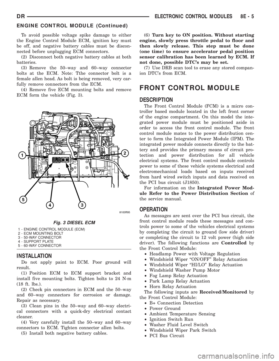
ECM form the vehicle (Fig. 3).
INSTALLATION
Do not apply paint to ECM. Poor ground will
result.
(1) Position ECM to ECM support bracket and
install five mounting bolts. Tighten bolts to 24 N´m
(18 ft. lbs.).
(2) Check pin connectors in ECM and the 50±way
and 60±way connectors for corrosion or damage.
Repair as necessary.
(3) Clean pins in the 50±way and 60±way electri-
cal connectors with a quick-dry electrical contact
cleaner.
(4) Very carefully install the 50±way and 60±way
connectors to ECM. Tighten connector allen bolts.
(5) Install both negative battery cables.(6)Turn key to ON position. Without starting
engine, slowly press throttle pedal to floor and
then slowly release. This step must be done
(one time) to ensure accelerator pedal position
sensor calibration has been learned by ECM. If
not done, possible DTC's may be set.
(7) Use DRB scan tool to erase any stored compan-
ion DTC's from ECM.
FRONT CONTROL MODULE
DESCRIPTION
The Front Control Module (FCM) is a micro con-
troller based module located in the left front corner
of the engine compartment. On this model the inte-
grated power module must be positioned aside in
order to access the front control module. The front
control module mates to the power distribution cen-
ter to form the Integrated Power Module (IPM). The
integrated power module connects directly to the bat-
tery and provides the primary means of circuit pro-
tection and power distribution for all vehicle
electrical systems. The front control module controls
power to some of these vehicle systems electrical and
electromechanical loads based on inputs received
from hard wired switch inputs and data received on
the PCI bus circuit (J1850).
For information on theIntegrated Power Mod-
ule Refer to the Power Distribution Sectionof
the service manual.
OPERATION
As messages are sent over the PCI bus circuit, the
front control module reads these messages and con-
trols power to some of the vehicles electrical systems
by completing the circuit to ground (low side driver)
or completing the circuit to 12 volt power (high side
driver). The following functions areControlledby
the Front Control Module:
²Headlamp Power with Voltage Regulation
²Windshield Wiper ªON/OFFº Relay Actuation
²Windshield Wiper ªHI/LOº Relay Actuation
²Windshield Washer Pump Motor
²Fog Lamp Relay Actuation
²Park Lamp Relay Actuation
²Horn Relay Actuation
The following inputs areReceived/Monitoredby
the Front Control Module:
²B+ Connection Detection
²Power Ground
²Ambient Temperature Sensing
²Ignition Switch Run
²Washer Fluid Level Switch
²Windshield Wiper Park Switch
²PCI Bus Circuit
Fig. 3 DIESEL ECM
1 - ENGINE CONTROL MODULE (ECM)
2 - ECM MOUNTING BOLT
3 - 50-WAY CONNECTOR
4 - SUPPORT PLATE
5 - 60-WAY CONNECTOR
DRELECTRONIC CONTROL MODULES 8E - 5
ENGINE CONTROL MODULE (Continued)
Page 387 of 2895
DIAGNOSIS AND TESTING - FRONT CONTROL
MODULE
The front control module is a printed circuit board
based module with a on-board micro-processor. The
front control module interfaces with other electronic
modules in the vehicle via the Programmable Com-
munications Interface (PCI) data bus (J1850). In
order to obtain conclusive testing the Programmable
Communications Interface (PCI) data bus network
and all of the electronic modules that provide inputs
to, or receive outputs from the front control module
must be checked. All PCI (J1850) communication
faults must be resolved prior to further diagnosing
any front control module related issues.
The front control module was designed to be diag-
nosed with an appropriate diagnostic scan tool, such
as the DRB IIIt. The most reliable, efficient, and
accurate means to diagnose the front control module
requires the use of a DRB IIItscan tool and the
proper Body Diagnostic Procedures manual.
Before any testing of the front control module is
attempted, the battery should be fully charged and
all wire harness and ground connections inspected
around the affected areas on the vehicle.
REMOVAL
(1) Disconnect the positive and negative battery
cables from the battery.
(2) Partially remove the integrated power module
from the engine compartment (Refer to 8 - ELECTRI-
CAL/POWER DISTRIBUTION/INTEGRATED
POWER MODULE - REMOVAL).
(3) Remove the front control module retaining
screws.
(4) Using both hands, pull the front control module
straightfrom the integrated power module assembly
to disconnect the 49-way electrical connector and
remove the front control module from the vehicle.
INSTALLATION
(1) Install the front control module on the inte-
grated power module assembly by pushing the
49-way electrical connector straight in.
(2) Install the front control module retaining
screws. Torque the screws to 7 in. lbs.
(3) Install the integrated power module (Refer to 8
- ELECTRICAL/POWER DISTRIBUTION/INTE-
GRATED POWER MODULE - INSTALLATION).
(4) Connect the positive and negative battery
cables.
HEATED SEAT MODULE
DESCRIPTION
The heated seat module is also known as the Seat
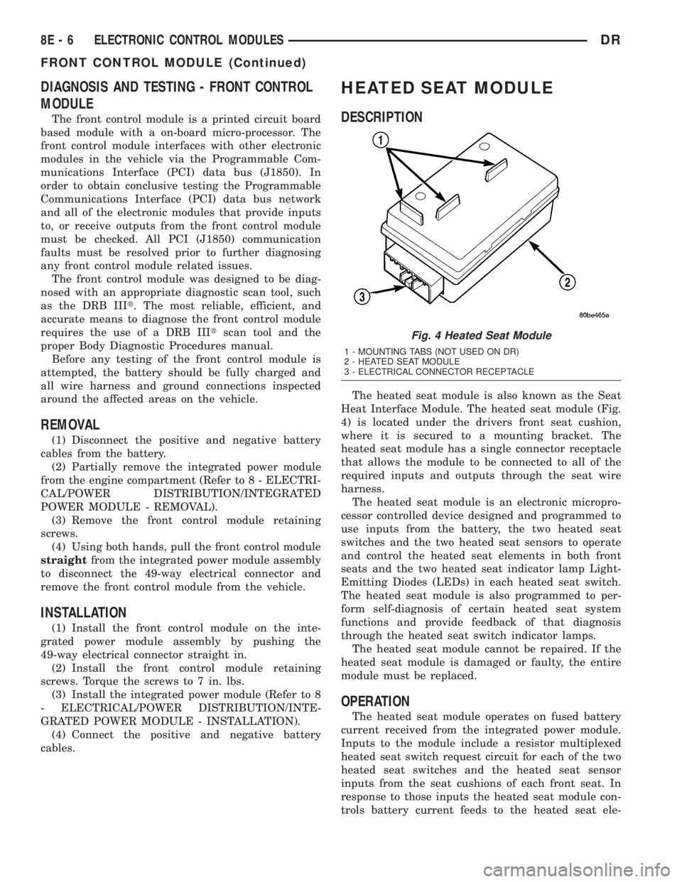
Heat Interface Module. The heated seat module (Fig.
4) is located under the drivers front seat cushion,
where it is secured to a mounting bracket. The
heated seat module has a single connector receptacle
that allows the module to be connected to all of the
required inputs and outputs through the seat wire
harness.
The heated seat module is an electronic micropro-
cessor controlled device designed and programmed to
use inputs from the battery, the two heated seat
switches and the two heated seat sensors to operate
and control the heated seat elements in both front
seats and the two heated seat indicator lamp Light-
Emitting Diodes (LEDs) in each heated seat switch.
The heated seat module is also programmed to per-
form self-diagnosis of certain heated seat system
functions and provide feedback of that diagnosis
through the heated seat switch indicator lamps.
The heated seat module cannot be repaired. If the
heated seat module is damaged or faulty, the entire
module must be replaced.
OPERATION
The heated seat module operates on fused battery
current received from the integrated power module.
Inputs to the module include a resistor multiplexed
heated seat switch request circuit for each of the two
heated seat switches and the heated seat sensor
inputs from the seat cushions of each front seat. In
response to those inputs the heated seat module con-
trols battery current feeds to the heated seat ele-
Fig. 4 Heated Seat Module
1 - MOUNTING TABS (NOT USED ON DR)
2 - HEATED SEAT MODULE
3 - ELECTRICAL CONNECTOR RECEPTACLE
8E - 6 ELECTRONIC CONTROL MODULESDR
FRONT CONTROL MODULE (Continued)