check engine DODGE RAM 2003 Service Manual PDF
[x] Cancel search | Manufacturer: DODGE, Model Year: 2003, Model line: RAM, Model: DODGE RAM 2003Pages: 2895, PDF Size: 83.15 MB
Page 392 of 2895
OPERATION
OPERATION - PCM
The PCM operates the fuel system. The PCM is a
pre-programmed, triple microprocessor digital com-
puter. It regulates ignition timing, air-fuel ratio,
emission control devices, charging system, certain
transmission features, speed control, air conditioning
compressor clutch engagement and idle speed. The
PCM can adapt its programming to meet changing
operating conditions.
The PCM receives input signals from various
switches and sensors. Based on these inputs, the
PCM regulates various engine and vehicle operations
through different system components. These compo-
nents are referred to as Powertrain Control Module
(PCM) Outputs. The sensors and switches that pro-
vide inputs to the PCM are considered Powertrain
Control Module (PCM) Inputs.
The PCM adjusts ignition timing based upon
inputs it receives from sensors that react to: engine
rpm, manifold absolute pressure, engine coolant tem-
perature, throttle position, transmission gear selec-
tion (automatic transmission), vehicle speed, power
steering pump pressure, and the brake switch.
The PCM adjusts idle speed based on inputs it
receives from sensors that react to: throttle position,
vehicle speed, transmission gear selection, engine
coolant temperature and from inputs it receives from
the air conditioning clutch switch and brake switch.
Based on inputs that it receives, the PCM adjusts
ignition coil dwell. The PCM also adjusts the gener-
ator charge rate through control of the generator
field and provides speed control operation.
NOTE: PCM Inputs:
²ABS module (if equipped)
²A/C request (if equipped with factory A/C)
²A/C select (if equipped with factory A/C)
²A/C pressure transducer
²Auto shutdown (ASD) sense
²Battery temperature sensor
²Battery voltage
²Brake switch
²J1850 bus (+) circuits
²J1850 bus (-) circuits
²Camshaft position sensor signal
²Crankshaft position sensor
²Data link connection for DRB scan tool
²EATX module (if equipped)
²Engine coolant temperature sensor
²Fuel level (through J1850 circuitry)
²Generator (battery voltage) output
²Ignition circuit sense (ignition switch in on/off/
crank/run position)²Intake manifold air temperature sensor
²Knock sensors (2 on 3.7L engine)
²Leak detection pump (switch) sense (if equipped)
²Manifold absolute pressure (MAP) sensor
²Oil pressure
²Oxygen sensors
²Park/neutral switch (auto. trans. only)
²Power ground
²Power steering pressure switch (if equipped)
²Sensor return
²Signal ground
²Speed control multiplexed single wire input
²Throttle position sensor
²Transfer case switch (4WD range position)
²Vehicle speed signal
NOTE: PCM Outputs:
²A/C clutch relay
²Auto shutdown (ASD) relay
²J1850 bus (+/-) circuits for: speedometer, voltme-
ter, fuel gauge, oil pressure gauge/lamp, engine temp.
gauge and speed control warn. lamp
²Data link connection for DRB scan tool
²EGR valve control solenoid (if equipped)
²EVAP canister purge solenoid
²Five volt sensor supply (primary)
²Five volt sensor supply (secondary)
²Fuel injectors
²Fuel pump relay
²Generator field driver (-)
²Generator field driver (+)
²Idle air control (IAC) motor
²Ignition coil(s)
²Leak detection pump (if equipped)
²Malfunction indicator lamp (Check engine lamp).
Driven through J1850 circuits.
²Oxygen sensor heater relays
²Oxygen sensors (pulse width modulated)
²Radiator cooling fan relay (pulse width modu-
lated)
²Speed control vacuum solenoid
²Speed control vent solenoid
²Tachometer (if equipped). Driven through J1850
circuits.
²Transmission convertor clutch circuit. Driven
through J1850 circuits.
OPERATION - 5 VOLT SUPPLIES
Primary 5±volt supply:
²supplies the required 5 volt power source to the
Crankshaft Position (CKP) sensor.
²supplies the required 5 volt power source to the
Camshaft Position (CMP) sensor.
²supplies a reference voltage for the Manifold
Absolute Pressure (MAP) sensor.
DRELECTRONIC CONTROL MODULES 8E - 11
POWERTRAIN CONTROL MODULE (Continued)
Page 394 of 2895
(2) Tighten bolts. Refer to torque specifications.
(3) Check pin connectors in the PCM and the three
32±way connectors (four 38±way connectors if
equipped with NGC) for corrosion or damage. Also,
the pin heights in connectors should all be same.
Repair as necessary before installing connectors.
(4) Install three 32±way connectors (four 38±way
connectors if equipped with NGC).
(5) Install cover over electrical connectors. Cover
snaps onto PCM.
(6) Install negative battery cable.
(7) Use the DRB scan tool to reprogram new PCM
with vehicles original Vehicle Identification Number
(VIN) and original vehicle mileage.
SENTRY KEY IMMOBILIZER
MODULE
DESCRIPTION
The Sentry Key Immobilizer Module (SKIM) con-
tains a Radio Frequency (RF) transceiver and a cen-
tral processing unit, which includes the Sentry Key
Immobilizer System (SKIS) program logic. The SKIS
programming enables the SKIM to program and
retain in memory the codes of at least two, but no
more than eight electronically coded Sentry Key
transponders. The SKIS programming also enables
the SKIM to communicate over the Programmable
Communication Interface (PCI) bus network with the
Powertrain Control Module (PCM), and/or the
DRBIIItscan tool.
OPERATION
The SKIM transmits and receives RF signals
through a tuned antenna enclosed within a molded
plastic ring that is integral to the SKIM housing.
When the SKIM is properly installed on the steering
column, the antenna ring is oriented around the igni-
tion lock cylinder housing. This antenna ring must be
located within eight millimeters (0.31 inches) of the
Sentry Key in order to ensure proper RF communica-
tion between the SKIM and the Sentry Key tran-
sponder.
For added system security, each SKIM is pro-
grammed with a unique ªSecret Keyº code and a
security code. The SKIM keeps the ªSecret Keyº code
in memory. The SKIM also sends the ªSecret Keyº
code to each of the programmed Sentry Key tran-
sponders. The security code is used by the assembly
plant to access the SKIS for initialization, or by the
dealer technician to access the system for service.
The SKIM also stores in its memory the Vehicle
Identification Number (VIN), which it learns through
a PCI bus message from the PCM during initializa-
tion.The SKIM and the PCM both use software that
includes a rolling code algorithm strategy, which
helps to reduce the possibility of unauthorized SKIS
disarming. The rolling code algorithm ensures secu-
rity by preventing an override of the SKIS through
the unauthorized substitution of the SKIM or the
PCM. However, the use of this strategy also means
that replacement of either the SKIM or the PCM
units will require a system initialization procedure to
restore system operation.
When the ignition switch is turned to the ON or
START positions, the SKIM transmits an RF signal
to excite the Sentry Key transponder. The SKIM then
listens for a return RF signal from the transponder
of the Sentry Key that is inserted in the ignition lock
cylinder. If the SKIM receives an RF signal with
valid ªSecret Keyº and transponder identification
codes, the SKIM sends a ªvalid keyº message to the
PCM over the PCI bus. If the SKIM receives an
invalid RF signal or no response, it sends ªinvalid
keyº messages to the PCM. The PCM will enable or
disable engine operation based upon the status of the
SKIM messages.
The SKIM also sends messages to the Instrument
Cluster which controls the VTSS indicator LED. The
SKIM sends messages to the Instrument Cluster to
turn the LED on for about three seconds when the
ignition switch is turned to the ON position as a bulb
test. After completion of the bulb test, the SKIM
sends bus messages to keep the LED off for a dura-
tion of about one second. Then the SKIM sends mes-
sages to turn the LED on or off based upon the
results of the SKIS self-tests. If the VTSS indicator
LED comes on and stays on after the bulb test, it
indicates that the SKIM has detected a system mal-
function and/or that the SKIS has become inopera-
tive.
If the SKIM detects an invalid key when the igni-
tion switch is turned to the ON position, it sends
messages to flash the VTSS indicator LED. The
SKIM can also send messages to flash the LED as an
indication to the customer that the SKIS has been
placed in it's ªCustomer Learnº programming mode.
See Sentry Key Immobilizer System Transponder
Programming in this section for more information on
the ªCustomer Learnº programming mode.
For diagnosis or initialization of the SKIM and the
PCM, a DRBIIItscan tool and the proper Powertrain
Diagnostic Procedures manual are required. The
SKIM cannot be repaired and, if faulty or damaged,
the unit must be replaced.
DRELECTRONIC CONTROL MODULES 8E - 13
POWERTRAIN CONTROL MODULE (Continued)
Page 395 of 2895
STANDARD PROCEDURE - PCM/SKIM
PROGRAMMING
NOTE: There are two procedures for transfering the
secret key to the SKIM:
²When ONLY the SKIM module is replaced, the
secret key is transfered from the PCM to the SKIM.
The ORGINAL KEYS may then be programmed to
the SKIM.
²When ONLY the PCM is replaced, then the
secret key is transfered from the SKIM to the PCM.
The ORGINAL KEYS may be used.
²When BOTH the SKIM and the PCM are
replaced the secret key is transferred from the
SKIM to the PCM, and NEW KEYS must be pro-
grammed.
NOTE: Before replacing the Powertrain Control
Module (PCM) for a failed driver, control circuit, or
ground circuit, be sure to check the related compo-
nent/circuit integrity for failures not detected due to
a double fault in the circuit. Most PCM driver/con-
trol circuit failures are caused by internal compo-
nent failures (i.e. relay and solenoids) and shorted
circuits (i.e. pull-ups, drivers and switched circuits).
These failures are difficult to detect when a double
fault has occurred and only one Diagnostic Trouble
Code (DTC) has set.
When a PCM (SBEC) and the Sentry Key Immobi-
lizer Module (SKIM) are replaced at the same time
perform the following steps in order:
(1) Program the new PCM (SBEC).
(2) Program the new SKIM.
(3) Replace all ignition keys and program them to
the new SKIM.
PROGRAMMING THE PCM (SBEC)
The Sentry Key Immobilizer System (SKIS) Secret
Key is an ID code that is unique to each SKIM. This
code is programmed and stored in the SKIM, PCM
and transponder chip (ignition keys). When replacing
the PCM it is necessary to program the secret key
into the new PCM using the DRBIIItscan tool. Per-
form the following steps to program the secret key
into the PCM.
(1) Turn the ignition switch on (transmission in
park/neutral).
(2) Use the DRBIIItscan tool and select THEFT
ALARM, SKIM then MISCELLANEOUS.
(3) Select PCM REPLACED (GAS ENGINE).
(4) Enter secured access mode by entering the
vehicle four-digit PIN.
(5) Select ENTER to update PCM VIN.NOTE: If three attempts are made to enter secure
access mode using an incorrect PIN, secured
access mode will be locked out for one hour. To
exit this lockout mode, turn the ignition to the RUN
position for one hour then enter the correct PIN.
(Ensure all accessories are turned OFF. Also moni-
tor the battery state and connect a battery charger
if necessary).
(6) Press ENTER to transfer the secret key (the
SKIM will send the secret key to the PCM).
(7) Press Page Back to get to the Select System
menu and select ENGINE, MISCELLANEOUS, and
SRI MEMORY CHECK.
(8) The DRBIIItscan tool will ask, Is odometer
reading between XX and XX? Select the YES or NO
button on the DRB IIItscan tool. If NO is selected,
the DRBIIItscan tool will read, Enter odometer
Reading
reading from the instrument cluster and press
ENTER.
PROGRAMMING THE SKIM
(1) Turn the ignition switch on (transmission in
park/neutral).
(2) Use the DRBIIItscan tool and select THEFT
ALARM, SKIM then MISCELLANEOUS.
(3) Select SKIM REPLACED (GAS ENGINE).
(4) Program the vehicle four-digit PIN into SKIM.
(5) Select COUNTRY CODE and enter the correct
country.
NOTE: Be sure to enter the correct country code. If
the incorrect country code is programmed into the
SKIM, the SKIM must be replaced.
(6) Select YES to update the VIN (the SKIM will
learn the VIN from the PCM).
(7) Press ENTER to transfer the secret key (the
PCM will send the secret key information to the
SKIM).
(8) Program ignition keys to the SKIM.
NOTE: If the PCM and the SKIM are replaced at the
same time, all vehicle keys will need to be replaced
and programmed to the new SKIM.
PROGRAMMING IGNITION KEYS TO THE SKIM
(1) Turn the ignition switch on (transmission in
park/neutral).
(2) Use the DRBIIItscan tool and select THEFT
ALARM, SKIM then MISCELLANEOUS.
(3) Select PROGRAM IGNITION KEY'S.
(4) Enter secured access mode by entering the
vehicle four-digit PIN.
8E - 14 ELECTRONIC CONTROL MODULESDR
SENTRY KEY IMMOBILIZER MODULE (Continued)
Page 407 of 2895
For battery system maintenance schedules and
jump starting procedures, see the owner's manual in
the vehicle glove box. Optionally, refer to the Lubri-
cation and Maintenance section of this manual for
the proper battery jump starting procedure. While
battery charging can be considered a maintenance
procedure, the battery charging procedure and
related information are located later in this section of
the service manual. This was done because the bat-
tery must be fully-charged before any battery system
diagnosis or testing procedures can be performed.
OPERATION
The battery system is designed to provide a safe,
efficient, reliable and mobile means of delivering and
storing electrical energy. This electrical energy is
required to operate the engine starting system, as
well as to operate many of the other vehicle acces-
sory systems for limited durations while the engine
and/or the charging system are not operating. The
battery system is also designed to provide a reserve
of electrical energy to supplement the charging sys-
tem for short durations while the engine is running
and the electrical current demands of the vehicle
exceed the output of the charging system. In addition
to delivering, and storing electrical energy for the
vehicle, the battery system serves as a capacitor and
voltage stabilizer for the vehicle electrical system. It
absorbs most abnormal or transient voltages caused
by the switching of any of the electrical components
or circuits in the vehicle.
DIAGNOSIS AND TESTING - BATTERY SYSTEM
The battery, starting, and charging systems in the
vehicle operate with one another and must be tested
as a complete system. In order for the engine to start
and the battery to maintain its charge properly, all of
the components that are used in these systems must
perform within specifications. It is important thatthe battery, starting, and charging systems be thor-
oughly tested and inspected any time a battery needs
to be charged or replaced. The cause of abnormal bat-
tery discharge, overcharging or early battery failure
must be diagnosed and corrected before a battery is
replaced and before a vehicle is returned to service.
The service information for these systems has been
separated within this service manual to make it eas-
ier to locate the specific information you are seeking.
However, when attempting to diagnose any of these
systems, it is important that you keep their interde-
pendency in mind.
The diagnostic procedures used for the battery,
starting, and charging systems include the most
basic conventional diagnostic methods, to the more
sophisticated On-Board Diagnostics (OBD) built into
the Powertrain Control Module (PCM). Use of an
induction-type milliampere ammeter, a volt/ohmme-
ter, a battery charger, a carbon pile rheostat (load
tester), a 12-volt test lamp and/or special service
tools may be required. All OBD-sensed systems are
monitored by the PCM. Each monitored circuit is
assigned a Diagnostic Trouble Code (DTC). The PCM
will store a DTC in electronic memory for any failure
it detects. Always check the PCM for stored trouble
codes before returning the vehicle to service. Refer to
Charging System for the proper charging system test
procedures. Refer to Starting System for the proper
starting system test procedures.
MICRO 420 BATTERY TESTER
The Micro 420 automotive battery tester is
designed to help the dealership technician diagnose a
defective battery. Follow the instruction manual sup-
plied with the tester to properly diagnose a battery.
If the instruction manual is not available, refer to
the standard procedure in this section, which
includes the directions for using the Micro 420 bat-
tery tester.
8F - 2 BATTERY SYSTEMDR
BATTERY SYSTEM (Continued)
Page 411 of 2895
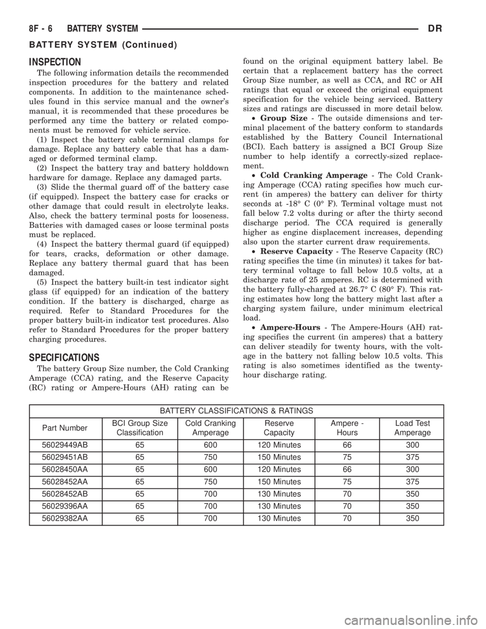
INSPECTION
The following information details the recommended
inspection procedures for the battery and related
components. In addition to the maintenance sched-
ules found in this service manual and the owner's
manual, it is recommended that these procedures be
performed any time the battery or related compo-
nents must be removed for vehicle service.
(1) Inspect the battery cable terminal clamps for
damage. Replace any battery cable that has a dam-
aged or deformed terminal clamp.
(2) Inspect the battery tray and battery holddown
hardware for damage. Replace any damaged parts.
(3) Slide the thermal guard off of the battery case
(if equipped). Inspect the battery case for cracks or
other damage that could result in electrolyte leaks.
Also, check the battery terminal posts for looseness.
Batteries with damaged cases or loose terminal posts
must be replaced.
(4) Inspect the battery thermal guard (if equipped)
for tears, cracks, deformation or other damage.
Replace any battery thermal guard that has been
damaged.
(5) Inspect the battery built-in test indicator sight
glass (if equipped) for an indication of the battery
condition. If the battery is discharged, charge as
required. Refer to Standard Procedures for the
proper battery built-in indicator test procedures. Also
refer to Standard Procedures for the proper battery
charging procedures.
SPECIFICATIONS
The battery Group Size number, the Cold Cranking
Amperage (CCA) rating, and the Reserve Capacity
(RC) rating or Ampere-Hours (AH) rating can befound on the original equipment battery label. Be
certain that a replacement battery has the correct
Group Size number, as well as CCA, and RC or AH
ratings that equal or exceed the original equipment
specification for the vehicle being serviced. Battery
sizes and ratings are discussed in more detail below.
²Group Size- The outside dimensions and ter-
minal placement of the battery conform to standards
established by the Battery Council International
(BCI). Each battery is assigned a BCI Group Size
number to help identify a correctly-sized replace-
ment.
²Cold Cranking Amperage- The Cold Crank-
ing Amperage (CCA) rating specifies how much cur-
rent (in amperes) the battery can deliver for thirty
seconds at -18É C (0É F). Terminal voltage must not
fall below 7.2 volts during or after the thirty second
discharge period. The CCA required is generally
higher as engine displacement increases, depending
also upon the starter current draw requirements.
²Reserve Capacity- The Reserve Capacity (RC)
rating specifies the time (in minutes) it takes for bat-
tery terminal voltage to fall below 10.5 volts, at a
discharge rate of 25 amperes. RC is determined with
the battery fully-charged at 26.7É C (80É F). This rat-
ing estimates how long the battery might last after a
charging system failure, under minimum electrical
load.
²Ampere-Hours- The Ampere-Hours (AH) rat-
ing specifies the current (in amperes) that a battery
can deliver steadily for twenty hours, with the volt-
age in the battery not falling below 10.5 volts. This
rating is also sometimes identified as the twenty-
hour discharge rating.
BATTERY CLASSIFICATIONS & RATINGS
Part NumberBCI Group Size
ClassificationCold Cranking
AmperageReserve
CapacityAmpere -
HoursLoad Test
Amperage
56029449AB 65 600 120 Minutes 66 300
56029451AB 65 750 150 Minutes 75 375
56028450AA 65 600 120 Minutes 66 300
56028452AA 65 750 150 Minutes 75 375
56028452AB 65 700 130 Minutes 70 350
56029396AA 65 700 130 Minutes 70 350
56029382AA 65 700 130 Minutes 70 350
8F - 6 BATTERY SYSTEMDR
BATTERY SYSTEM (Continued)
Page 420 of 2895
also provide a return path for electrical current gen-
erated by the charging system for restoring the volt-
age potential of the battery. The female battery
terminal clamps on the ends of the battery cable
wires provide a strong and reliable connection of the
battery cable to the battery terminal posts. The ter-
minal pinch bolts allow the female terminal clamps
to be tightened around the male terminal posts on
the top of the battery. The eyelet terminals secured
to the ends of the battery cable wires opposite the
female battery terminal clamps provide secure and
reliable connection of the battery to the vehicle elec-
trical system.
DIAGNOSIS AND TESTING - BATTERY CABLES
A voltage drop test will determine if there is exces-
sive resistance in the battery cable terminal connec-
tions or the battery cables. If excessive resistance is
found in the battery cable connections, the connec-
tion point should be disassembled, cleaned of all cor-
rosion or foreign material, then reassembled.
Following reassembly, check the voltage drop for the
battery cable connection and the battery cable again
to confirm repair.
When performing the voltage drop test, it is impor-
tant to remember that the voltage drop is giving an
indication of the resistance between the two points at
which the voltmeter probes are attached.EXAM-
PLE:When testing the resistance of the battery pos-
itive cable, touch the voltmeter leads to the battery
positive cable terminal clamp and to the battery pos-
itive cable eyelet terminal at the starter solenoid
B(+) terminal stud. If you probe the battery positive
terminal post and the battery positive cable eyelet
terminal at the starter solenoid B(+) terminal stud,
you are reading the combined voltage drop in the
battery positive cable terminal clamp-to-terminal
post connection and the battery positive cable.
VOLTAGE DROP TEST
WARNING: MODELS EQUIPPED WITH A DIESEL
ENGINE HAVE AN AUTOMATIC SHUTDOWN (ASD)
RELAY LOCATED IN THE POWER DISTRIBUTION
CENTER (PDC). REMOVAL OF THE ASD RELAY
MAY NOT PREVENT THE DIESEL ENGINE FROM
STARTING. BE CERTAIN TO DISCONNECT THE
FUEL SHUTDOWN SOLENOID WIRE HARNESS
CONNECTOR TO PREVENT THE ENGINE FROM
STARTING. FAILURE TO DO SO MAY RESULT IN
PERSONAL INJURY.
The following operation will require a voltmeter
accurate to 1/10 (0.10) volt. Before performing this
test, be certain that the following procedures are
accomplished:²The battery is fully-charged and tested (Refer to
8 - ELECTRICAL/BATTERY SYSTEM/BATTERY -
STANDARD PROCEDURE).
²Fully engage the parking brake.
²If the vehicle is equipped with an automatic
transmission, place the gearshift selector lever in the
Park position. If the vehicle is equipped with a man-
ual transmission, place the gearshift selector lever in
the Neutral position and block the clutch pedal in the
fully depressed position.
²Verify that all lamps and accessories are turned
off.
²To prevent a gasoline engine from starting,
remove the Automatic ShutDown (ASD) relay. The
ASD relay is located in the Integrated Power Module
(IPM), in the engine compartment. See the fuse and
relay layout label on the underside of the IPM cover
for ASD relay identification and location.
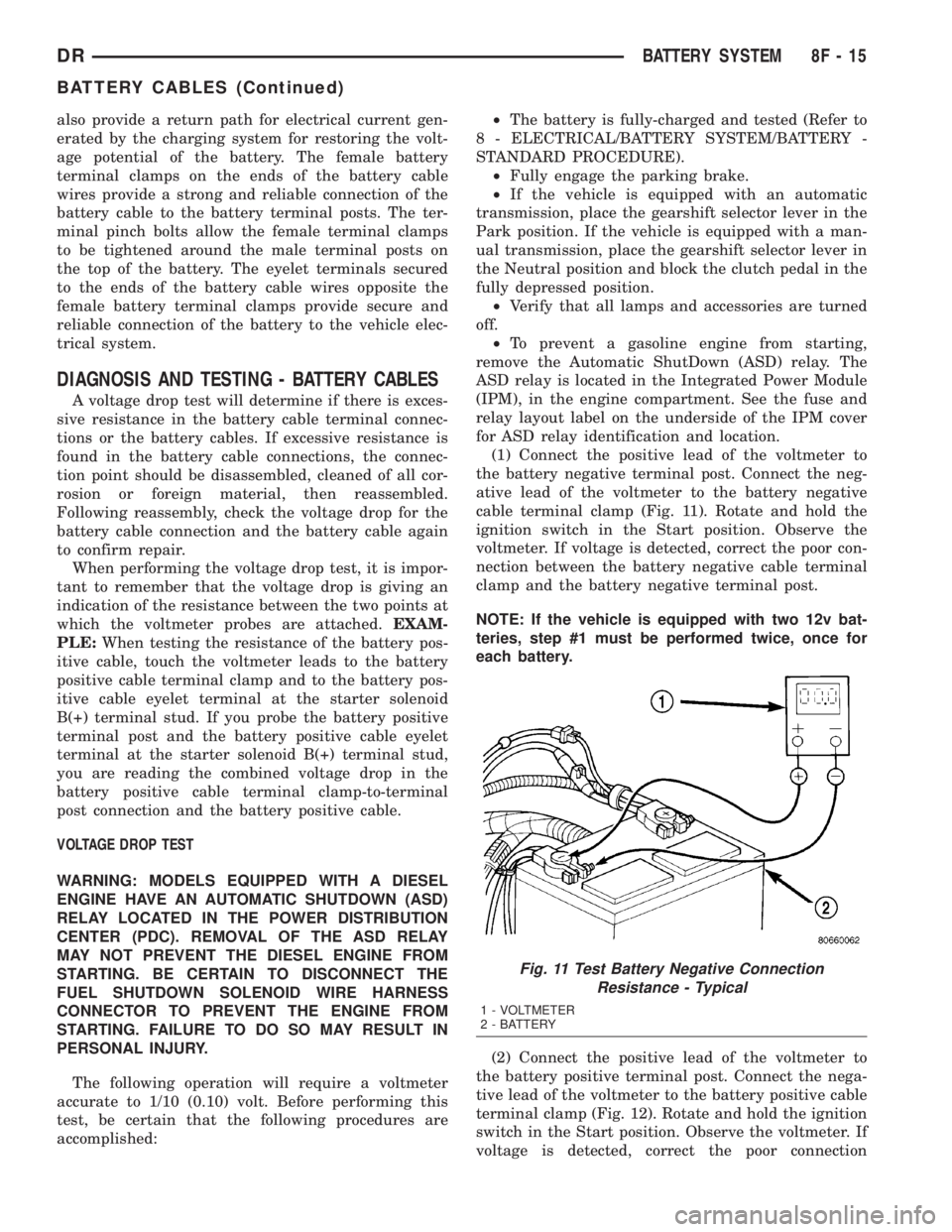
(1) Connect the positive lead of the voltmeter to
the battery negative terminal post. Connect the neg-
ative lead of the voltmeter to the battery negative
cable terminal clamp (Fig. 11). Rotate and hold the
ignition switch in the Start position. Observe the
voltmeter. If voltage is detected, correct the poor con-
nection between the battery negative cable terminal
clamp and the battery negative terminal post.
NOTE: If the vehicle is equipped with two 12v bat-
teries, step #1 must be performed twice, once for
each battery.
(2) Connect the positive lead of the voltmeter to
the battery positive terminal post. Connect the nega-
tive lead of the voltmeter to the battery positive cable
terminal clamp (Fig. 12). Rotate and hold the ignition
switch in the Start position. Observe the voltmeter. If
voltage is detected, correct the poor connection
Fig. 11 Test Battery Negative Connection
Resistance - Typical
1 - VOLTMETER
2 - BATTERY
DRBATTERY SYSTEM 8F - 15
BATTERY CABLES (Continued)
Page 424 of 2895
CHARGING
TABLE OF CONTENTS
page page
CHARGING
DESCRIPTION.........................19
OPERATION...........................19
DIAGNOSIS AND TESTING - CHARGING
SYSTEM............................19
SPECIFICATIONS
GENERATOR RATINGS.................20
SPECIFICATIONS - TORQUE - GENERATOR
/ CHARGING SYSTEM..................20
BATTERY TEMPERATURE SENSOR
DESCRIPTION.........................21OPERATION...........................21
REMOVAL.............................21
INSTALLATION.........................21
GENERATOR
DESCRIPTION.........................22
OPERATION...........................22
REMOVAL.............................22
INSTALLATION.........................25
VOLTAGE REGULATOR
DESCRIPTION.........................27
OPERATION...........................27
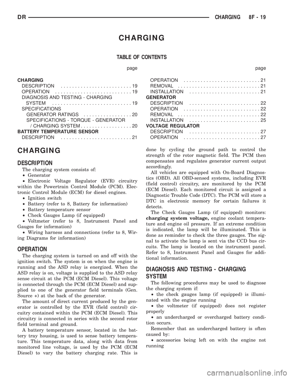
CHARGING
DESCRIPTION
The charging system consists of:
²Generator
²Electronic Voltage Regulator (EVR) circuitry
within the Powertrain Control Module (PCM). Elec-
tronic Control Module (ECM) for diesel engines.
²Ignition switch
²Battery (refer to 8, Battery for information)
²Battery temperature sensor
²Check Gauges Lamp (if equipped)
²Voltmeter (refer to 8, Instrument Panel and
Gauges for information)
²Wiring harness and connections (refer to 8, Wir-
ing Diagrams for information)
OPERATION
The charging system is turned on and off with the
ignition switch. The system is on when the engine is
running and the ASD relay is energized. When the
ASD relay is on, voltage is supplied to the ASD relay
sense circuit at the PCM (ECM Diesel). This voltage
is connected through the PCM (ECM Diesel) and sup-
plied to one of the generator field terminals (Gen.
Source +) at the back of the generator.
The amount of direct current produced by the gen-
erator is controlled by the EVR (field control) cir-
cuitry contained within the PCM (ECM Diesel). This
circuitry is connected in series with the second rotor
field terminal and ground.
A battery temperature sensor, located in the bat-
tery tray housing, is used to sense battery tempera-
ture. This temperature data, along with data from
monitored line voltage, is used by the PCM (ECM
Diesel) to vary the battery charging rate. This isdone by cycling the ground path to control the
strength of the rotor magnetic field. The PCM then
compensates and regulates generator current output
accordingly.
All vehicles are equipped with On-Board Diagnos-
tics (OBD). All OBD-sensed systems, including EVR
(field control) circuitry, are monitored by the PCM
(ECM Diesel). Each monitored circuit is assigned a
Diagnostic Trouble Code (DTC). The PCM will store a
DTC in electronic memory for certain failures it
detects.
The Check Gauges Lamp (if equipped) monitors:
charging system voltage,engine coolant tempera-
ture and engine oil pressure. If an extreme condition
is indicated, the lamp will be illuminated. This is
done as reminder to check the three gauges. The sig-
nal to activate the lamp is sent via the CCD bus cir-
cuits. The lamp is located on the instrument panel.
Refer to 8, Instrument Panel and Gauges for addi-
tional information.
DIAGNOSIS AND TESTING - CHARGING
SYSTEM
The following procedures may be used to diagnose
the charging system if:
²the check gauges lamp (if equipped) is illumi-
nated with the engine running
²the voltmeter (if equipped) does not register
properly
²an undercharged or overcharged battery condi-
tion occurs.
Remember that an undercharged battery is often
caused by:
²accessories being left on with the engine not
running
DRCHARGING 8F - 19
Page 425 of 2895
²a faulty or improperly adjusted switch that
allows a lamp to stay on. Refer to Ignition-Off Draw
Test in 8, Battery for more information.
INSPECTION
The PCM (Powertrain Control Module), or ECM
(Diesel) monitors critical input and output circuits of
the charging system, making sure they are opera-
tional. A Diagnostic Trouble Code (DTC) is assigned
to each input and output circuit monitored by the
On-Board Diagnostic (OBD) system. Some charging
system circuits are checked continuously, and some
are checked only under certain conditions.
Refer to Diagnostic Trouble Codes in; Powertrain
Control Module; Electronic Control Modules for more
DTC information. This will include a complete list of
DTC's including DTC's for the charging system.
To perform a complete test of the charging system,
refer to the appropriate Powertrain Diagnostic Proce-
dures service manual and the DRBtscan tool. Per-
form the following inspections before attaching the
scan tool.
(1) Inspect the battery condition. Refer to 8, Bat-
tery for procedures.(2) Inspect condition of battery cable terminals,
battery posts, connections at engine block, starter
solenoid and relay. They should be clean and tight.
Repair as required.
(3) Inspect all fuses in both the fuseblock and
Power Distribution Center (PDC) for tightness in
receptacles. They should be properly installed and
tight. Repair or replace as required.
(4) Inspect generator mounting bolts for tightness.
Replace or tighten bolts if required. Refer to the Gen-
erator Removal/Installation section of this group for
torque specifications.
(5) Inspect generator drive belt condition and ten-
sion. Tighten or replace belt as required. Refer to
Belt Tension Specifications in 7, Cooling System.
(6) Inspect automatic belt tensioner (if equipped).
Refer to 7, Cooling System for information.
(7) Inspect generator electrical connections at gen-
erator field, battery output, and ground terminal (if
equipped). Also check generator ground wire connec-
tion at engine (if equipped). They should all be clean
and tight. Repair as required.
SPECIFICATIONS
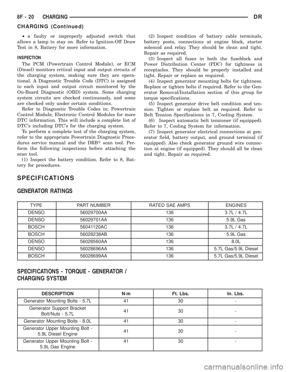
GENERATOR RATINGS
TYPE PART NUMBER RATED SAE AMPS ENGINES
DENSO 56029700AA 136 3.7L / 4.7L
DENSO 56029701AA 136 5.9L Gas
BOSCH 56041120AC 136 3.7L / 4.7L
BOSCH 56028238AB 136 5.9L Gas
DENSO 56028560AA 136 8.0L
DENSO 56028696AA 136 5.7L Gas/5.9L Diesel
BOSCH 56028699AA 136 5.7L Gas/5.9L Diesel
SPECIFICATIONS - TORQUE - GENERATOR /
CHARGING SYSTEM
DESCRIPTION N´m Ft. Lbs. In. Lbs.
Generator Mounting Bolts - 5.7L 41 30 -
Generator Support Bracket
Bolt/Nuts - 5.7L41 30 -
Generator Mounting Bolts - 8.0L 41 30 -
Generator Upper Mounting Bolt -
5.9L Diesel Engine41 30 -
Generator Upper Mounting Bolt -
5.9L Gas Engine41 30 -
8F - 20 CHARGINGDR
CHARGING (Continued)
Page 439 of 2895
SPECIFICATIONS - TORQUE - STARTING
SYSTEM
DESCRIPTION N´m Ft. Lbs. In. Lbs.
Battery Cable Eyelet Nut at
Solenoid (large nut - gas engines)25 19 221
Battery Cable Eyelet Nut at
Solenoid (large nut - diesel engine)14 - 120
Starter Solenoid Nut (small nut -
diesel engine)6-55
Starter Mounting Bolts - Gas
Engines68 50 -
Starter Mounting Nut - Gas Engines 68 50 -
Starter Mounting Bolts - Diesel 43 32 -
STARTER MOTOR
DIAGNOSIS AND TESTING - STARTER MOTOR
Correct starter motor operation can be confirmed
by performing the following free running bench test.
This test can only be performed with starter motor
removed from vehicle. Refer to Specifications for
starter motor specifications.
(1) Remove starter motor from vehicle. Refer to
Starter Motor Removal and Installation.
(2) Mount starter motor securely in a soft-jawed
bench vise. The vise jaws should be clamped on the
mounting flange of starter motor. Never clamp on
starter motor by field frame.
(3) Connect a suitable volt-ampere tester and a
12-volt battery to starter motor in series, and set
ammeter to 100 ampere scale. See instructions pro-
vided by manufacturer of volt-ampere tester being
used.
(4) Install jumper wire from solenoid terminal to
solenoid battery terminal. The starter motor should
operate. If starter motor fails to operate, replace
faulty starter motor assembly.
(5) Adjust carbon pile load of tester to obtain free
running test voltage. Refer to Specifications for
starter motor free running test voltage specifications.
(6) Note reading on ammeter and compare reading
to free running test maximum amperage draw. Refer
to Specifications for starter motor free running test
maximum amperage draw specifications.
(7) If ammeter reading exceeds maximum amper-
age draw specification, replace faulty starter motor
assembly.
STARTER SOLENOID
This test can only be performed with starter motor
removed from vehicle.(1) Remove starter motor from vehicle. Refer to
Starter Motor Removal and Installation.
(2) Disconnect wire from solenoid field coil termi-
nal.
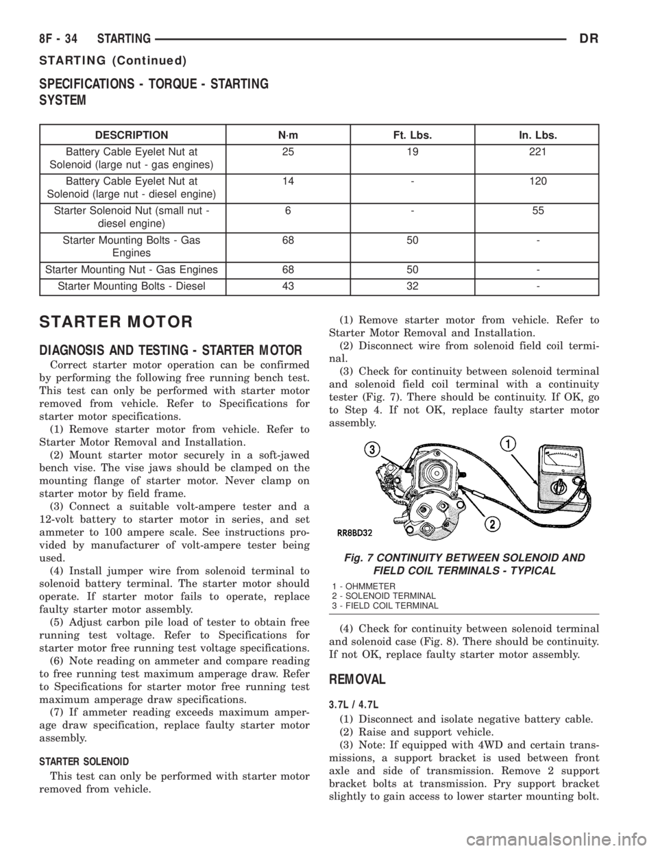
(3) Check for continuity between solenoid terminal
and solenoid field coil terminal with a continuity
tester (Fig. 7). There should be continuity. If OK, go
to Step 4. If not OK, replace faulty starter motor
assembly.
(4) Check for continuity between solenoid terminal
and solenoid case (Fig. 8). There should be continuity.
If not OK, replace faulty starter motor assembly.
REMOVAL
3.7L / 4.7L
(1) Disconnect and isolate negative battery cable.
(2) Raise and support vehicle.
(3) Note: If equipped with 4WD and certain trans-
missions, a support bracket is used between front
axle and side of transmission. Remove 2 support
bracket bolts at transmission. Pry support bracket
slightly to gain access to lower starter mounting bolt.
Fig. 7 CONTINUITY BETWEEN SOLENOID AND
FIELD COIL TERMINALS - TYPICAL
1 - OHMMETER
2 - SOLENOID TERMINAL
3 - FIELD COIL TERMINAL
8F - 34 STARTINGDR
STARTING (Continued)
Page 443 of 2895
STARTER MOTOR RELAY
DESCRIPTION
The starter relay is an electromechanical device
that switches battery current to the pull-in coil of the
starter solenoid when ignition switch is turned to
Start position. The starter relay is located in the
Power Distribution Center (PDC) in the engine com-
partment. See PDC cover for relay identification and
location.
The starter relay is a International Standards
Organization (ISO) relay. Relays conforming to ISO
specifications have common physical dimensions, cur-
rent capacities, terminal patterns, and terminal func-
tions.
The starter relay cannot be repaired or adjusted. If
faulty or damaged, it must be replaced.
OPERATION
The ISO relay consists of an electromagnetic coil, a
resistor or diode, and three (two fixed and one mov-
able) electrical contacts. The movable (common feed)
relay contact is held against one of the fixed contacts
(normally closed) by spring pressure. When electro-
magnetic coil is energized, it draws the movable con-
tact away from normally closed fixed contact, and
holds it against the other (normally open) fixed con-
tact.
When electromagnetic coil is de-energized, spring
pressure returns movable contact to normally closed
position. The resistor or diode is connected in parallel
with electromagnetic coil within relay, and helps to
dissipate voltage spikes produced when coil is de-en-
ergized.
DIAGNOSIS AND TESTING - STARTER RELAY
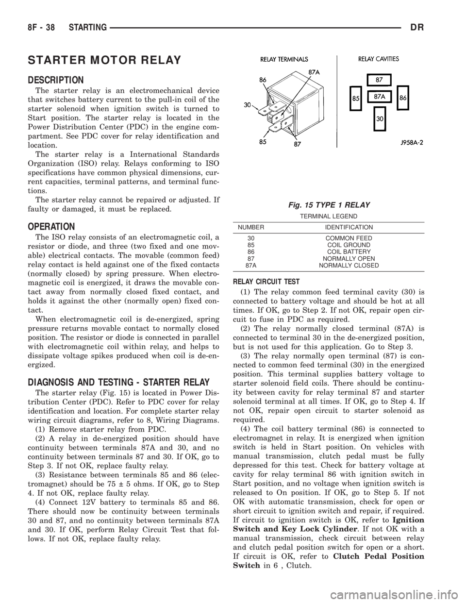
The starter relay (Fig. 15) is located in Power Dis-
tribution Center (PDC). Refer to PDC cover for relay
identification and location. For complete starter relay
wiring circuit diagrams, refer to 8, Wiring Diagrams.
(1) Remove starter relay from PDC.
(2) A relay in de-energized position should have
continuity between terminals 87A and 30, and no
continuity between terminals 87 and 30. If OK, go to
Step 3. If not OK, replace faulty relay.
(3) Resistance between terminals 85 and 86 (elec-
tromagnet) should be 75 5 ohms. If OK, go to Step
4. If not OK, replace faulty relay.
(4) Connect 12V battery to terminals 85 and 86.
There should now be continuity between terminals
30 and 87, and no continuity between terminals 87A
and 30. If OK, perform Relay Circuit Test that fol-
lows. If not OK, replace faulty relay.RELAY CIRCUIT TEST
(1) The relay common feed terminal cavity (30) is
connected to battery voltage and should be hot at all
times. If OK, go to Step 2. If not OK, repair open cir-
cuit to fuse in PDC as required.
(2) The relay normally closed terminal (87A) is
connected to terminal 30 in the de-energized position,
but is not used for this application. Go to Step 3.
(3) The relay normally open terminal (87) is con-
nected to common feed terminal (30) in the energized
position. This terminal supplies battery voltage to
starter solenoid field coils. There should be continu-
ity between cavity for relay terminal 87 and starter
solenoid terminal at all times. If OK, go to Step 4. If
not OK, repair open circuit to starter solenoid as
required.
(4) The coil battery terminal (86) is connected to
electromagnet in relay. It is energized when ignition
switch is held in Start position. On vehicles with
manual transmission, clutch pedal must be fully
depressed for this test. Check for battery voltage at
cavity for relay terminal 86 with ignition switch in
Start position, and no voltage when ignition switch is
released to On position. If OK, go to Step 5. If not
OK with automatic transmission, check for open or
short circuit to ignition switch and repair, if required.
If circuit to ignition switch is OK, refer toIgnition
Switch and Key Lock Cylinder. If not OK with a
manual transmission, check circuit between relay
and clutch pedal position switch for open or a short.
If circuit is OK, refer toClutch Pedal Position
Switchin 6 , Clutch.
Fig. 15 TYPE 1 RELAY
TERMINAL LEGEND
NUMBER IDENTIFICATION
30 COMMON FEED
85 COIL GROUND
86 COIL BATTERY
87 NORMALLY OPEN
87A NORMALLY CLOSED
8F - 38 STARTINGDR