check engine DODGE RAM 2003 Service Manual Online
[x] Cancel search | Manufacturer: DODGE, Model Year: 2003, Model line: RAM, Model: DODGE RAM 2003Pages: 2895, PDF Size: 83.15 MB
Page 465 of 2895
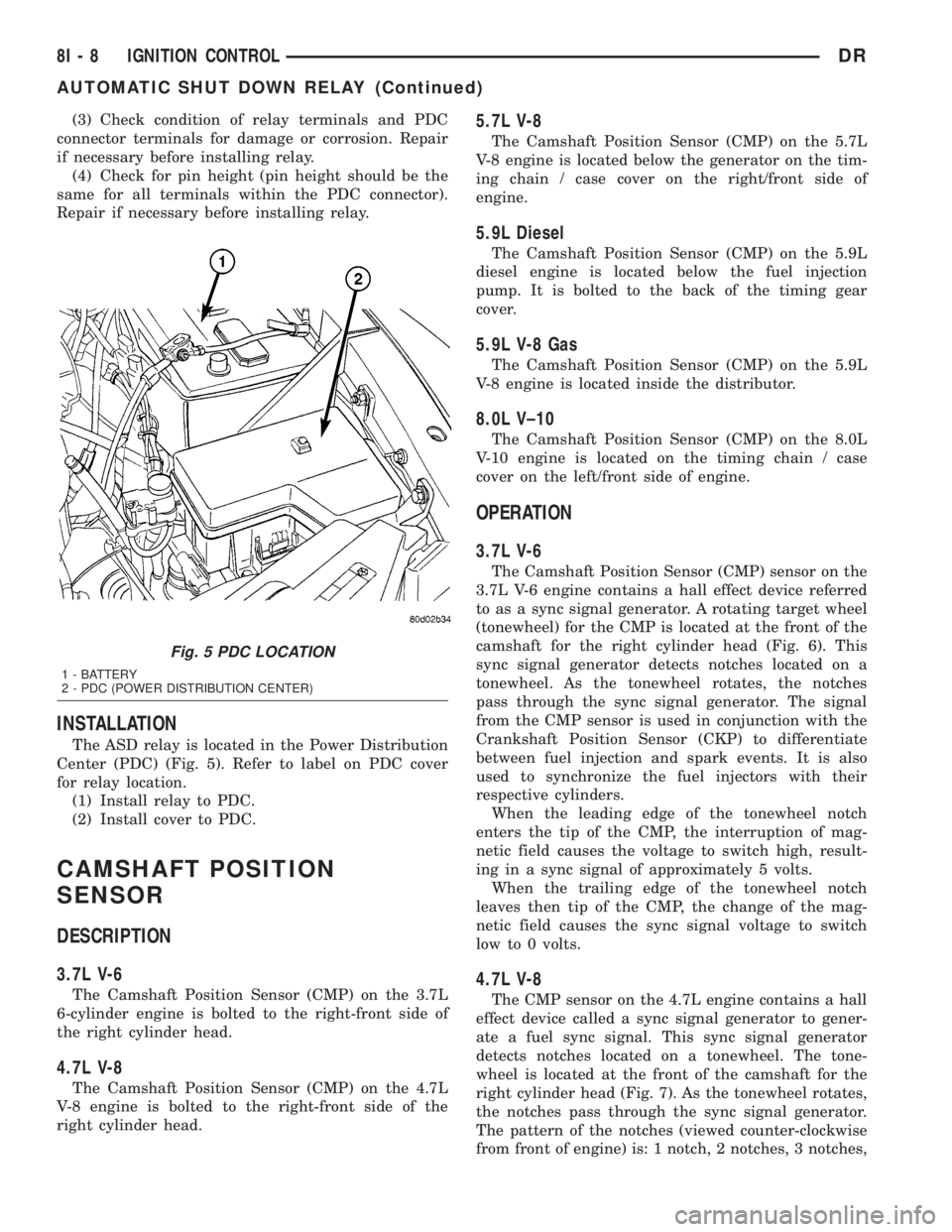
(3) Check condition of relay terminals and PDC
connector terminals for damage or corrosion. Repair
if necessary before installing relay.
(4) Check for pin height (pin height should be the
same for all terminals within the PDC connector).
Repair if necessary before installing relay.
INSTALLATION
The ASD relay is located in the Power Distribution
Center (PDC) (Fig. 5). Refer to label on PDC cover
for relay location.
(1) Install relay to PDC.
(2) Install cover to PDC.
CAMSHAFT POSITION
SENSOR
DESCRIPTION
3.7L V-6
The Camshaft Position Sensor (CMP) on the 3.7L
6-cylinder engine is bolted to the right-front side of
the right cylinder head.
4.7L V-8
The Camshaft Position Sensor (CMP) on the 4.7L
V-8 engine is bolted to the right-front side of the
right cylinder head.
5.7L V-8
The Camshaft Position Sensor (CMP) on the 5.7L
V-8 engine is located below the generator on the tim-
ing chain / case cover on the right/front side of
engine.
5.9L Diesel
The Camshaft Position Sensor (CMP) on the 5.9L
diesel engine is located below the fuel injection
pump. It is bolted to the back of the timing gear
cover.
5.9L V-8 Gas
The Camshaft Position Sensor (CMP) on the 5.9L
V-8 engine is located inside the distributor.
8.0L V±10
The Camshaft Position Sensor (CMP) on the 8.0L
V-10 engine is located on the timing chain / case
cover on the left/front side of engine.
OPERATION
3.7L V-6
The Camshaft Position Sensor (CMP) sensor on the
3.7L V-6 engine contains a hall effect device referred
to as a sync signal generator. A rotating target wheel
(tonewheel) for the CMP is located at the front of the
camshaft for the right cylinder head (Fig. 6). This
sync signal generator detects notches located on a
tonewheel. As the tonewheel rotates, the notches
pass through the sync signal generator. The signal
from the CMP sensor is used in conjunction with the
Crankshaft Position Sensor (CKP) to differentiate
between fuel injection and spark events. It is also
used to synchronize the fuel injectors with their
respective cylinders.
When the leading edge of the tonewheel notch
enters the tip of the CMP, the interruption of mag-
netic field causes the voltage to switch high, result-
ing in a sync signal of approximately 5 volts.
When the trailing edge of the tonewheel notch
leaves then tip of the CMP, the change of the mag-
netic field causes the sync signal voltage to switch
low to 0 volts.
4.7L V-8
The CMP sensor on the 4.7L engine contains a hall
effect device called a sync signal generator to gener-
ate a fuel sync signal. This sync signal generator
detects notches located on a tonewheel. The tone-
wheel is located at the front of the camshaft for the
right cylinder head (Fig. 7). As the tonewheel rotates,
the notches pass through the sync signal generator.
The pattern of the notches (viewed counter-clockwise
from front of engine) is: 1 notch, 2 notches, 3 notches,
Fig. 5 PDC LOCATION
1 - BATTERY
2 - PDC (POWER DISTRIBUTION CENTER)
8I - 8 IGNITION CONTROLDR
AUTOMATIC SHUT DOWN RELAY (Continued)
Page 468 of 2895
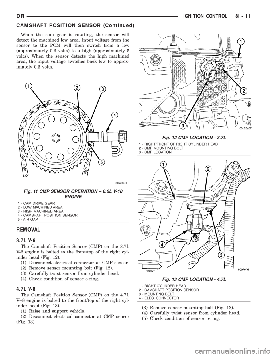
When the cam gear is rotating, the sensor will
detect the machined low area. Input voltage from the
sensor to the PCM will then switch from a low
(approximately 0.3 volts) to a high (approximately 5
volts). When the sensor detects the high machined
area, the input voltage switches back low to approx-
imately 0.3 volts.
REMOVAL
3.7L V-6
The Camshaft Position Sensor (CMP) on the 3.7L
V-6 engine is bolted to the front/top of the right cyl-
inder head (Fig. 12).
(1) Disconnect electrical connector at CMP sensor.
(2) Remove sensor mounting bolt (Fig. 12).
(3) Carefully twist sensor from cylinder head.
(4) Check condition of sensor o-ring.
4.7L V-8
The Camshaft Position Sensor (CMP) on the 4.7L
V±8 engine is bolted to the front/top of the right cyl-
inder head (Fig. 13).
(1) Raise and support vehicle.
(2) Disconnect electrical connector at CMP sensor
(Fig. 13).(3) Remove sensor mounting bolt (Fig. 13).
(4) Carefully twist sensor from cylinder head.
(5) Check condition of sensor o-ring.
Fig. 11 CMP SENSOR OPERATION ± 8.0L V-10
ENGINE
1 - CAM DRIVE GEAR
2 - LOW MACHINED AREA
3 - HIGH MACHINED AREA
4 - CAMSHAFT POSITION SENSOR
5 - AIR GAP
Fig. 12 CMP LOCATION - 3.7L
1 - RIGHT/FRONT OF RIGHT CYLINDER HEAD
2 - CMP MOUNTING BOLT
3 - CMP LOCATION
Fig. 13 CMP LOCATION - 4.7L
1 - RIGHT CYLINDER HEAD
2 - CAMSHAFT POSITION SENSOR
3 - MOUNTING BOLT
4 - ELEC. CONNECTOR
DRIGNITION CONTROL 8I - 11
CAMSHAFT POSITION SENSOR (Continued)
Page 469 of 2895
5.7L V-8
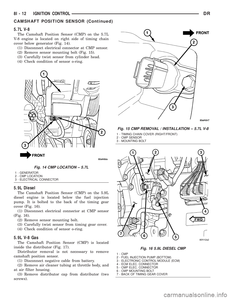
The Camshaft Position Sensor (CMP) on the 5.7L
V-8 engine is located on right side of timing chain
cover below generator (Fig. 14).
(1) Disconnect electrical connector at CMP sensor.
(2) Remove sensor mounting bolt (Fig. 15).
(3) Carefully twist sensor from cylinder head.
(4) Check condition of sensor o-ring.
5.9L Diesel
The Camshaft Position Sensor (CMP) on the 5.9L
diesel engine is located below the fuel injection
pump. It is bolted to the back of the timing gear
cover (Fig. 16).
(1) Disconnect electrical connector at CMP sensor
(Fig. 16).
(2) Remove sensor mounting bolt.
(3) Carefully twist sensor from timing gear cover.
(4) Check condition of sensor o-ring.
5.9L V-8 Gas
The Camshaft Position Sensor (CMP) is located
inside the distributor (Fig. 17).
Distributor removal is not necessary to remove
camshaft position sensor.
(1) Disconnect negative cable from battery.
(2) Remove air cleaner tubing at throttle body, and
at air filter housing.
(3) Remove distributor cap from distributor (two
screws).
Fig. 14 CMP LOCATION ± 5.7L
1 - GENERATOR
2 - CMP LOCATION
3 - ELECTRICAL CONNECTOR
Fig. 15 CMP REMOVAL / INSTALLATION ± 5.7L V-8
1 - TIMING CHAIN COVER (RIGHT/FRONT)
2 - CMP SENSOR
3 - MOUNTING BOLT
Fig. 16 5.9L DIESEL CMP
1 - CMP
2 - FUEL INJECTION PUMP (BOTTOM)
3 - ELECTRONIC CONTROL MODULE (ECM)
4 - ECM ELEC. CONNECTOR
5 - CMP ELEC. CONNECTOR
6 - CMP MOUNTING BOLT
7 - BACK OF TIMING GEAR COVER
8I - 12 IGNITION CONTROLDR
CAMSHAFT POSITION SENSOR (Continued)
Page 470 of 2895
(4) Disconnect camshaft position sensor wiring
harness from main engine wiring harness.
(5) Remove distributor rotor from distributor shaft.
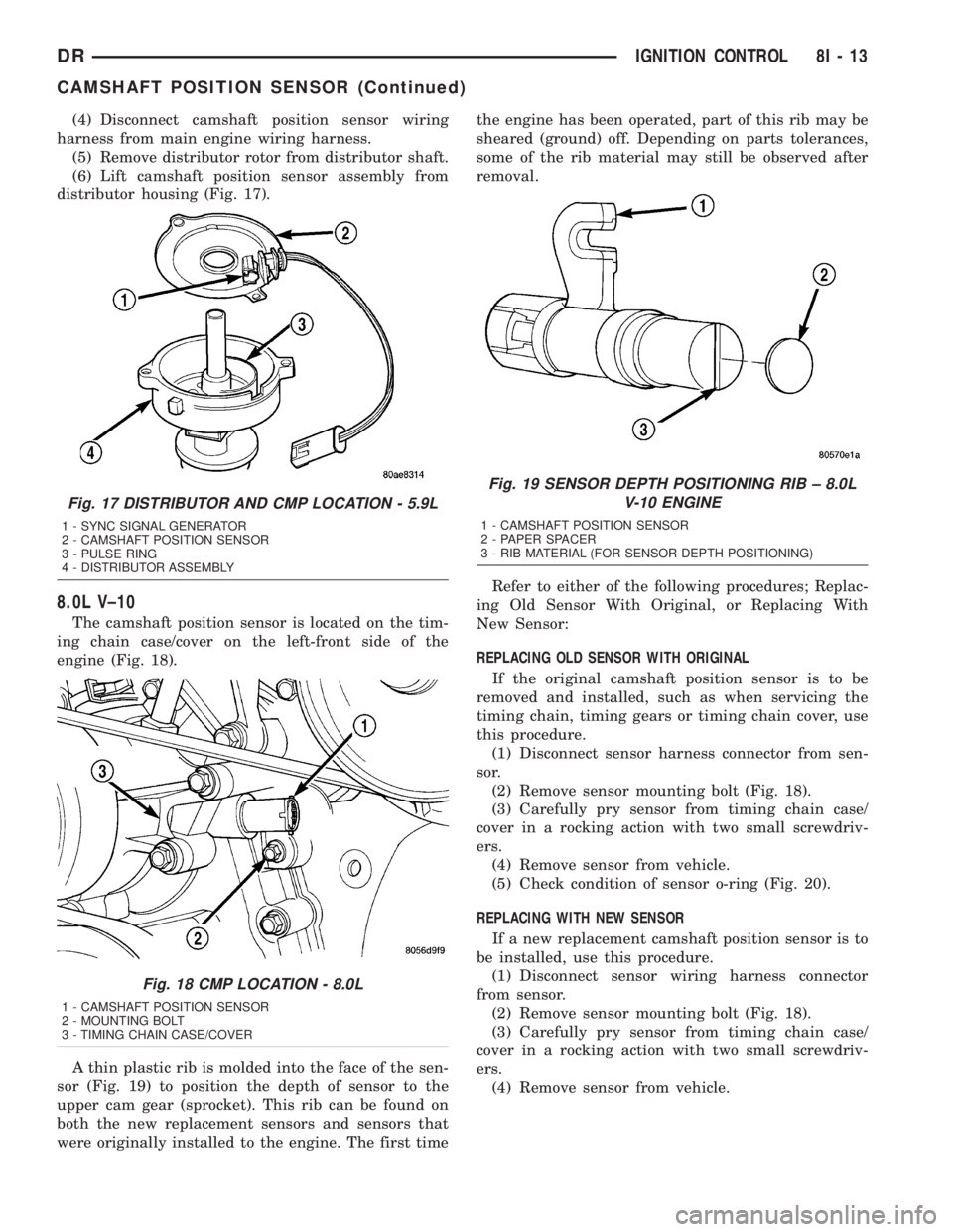
(6) Lift camshaft position sensor assembly from
distributor housing (Fig. 17).
8.0L V±10
The camshaft position sensor is located on the tim-
ing chain case/cover on the left-front side of the
engine (Fig. 18).
A thin plastic rib is molded into the face of the sen-
sor (Fig. 19) to position the depth of sensor to the
upper cam gear (sprocket). This rib can be found on
both the new replacement sensors and sensors that
were originally installed to the engine. The first timethe engine has been operated, part of this rib may be
sheared (ground) off. Depending on parts tolerances,
some of the rib material may still be observed after
removal.
Refer to either of the following procedures; Replac-
ing Old Sensor With Original, or Replacing With
New Sensor:
REPLACING OLD SENSOR WITH ORIGINAL
If the original camshaft position sensor is to be
removed and installed, such as when servicing the
timing chain, timing gears or timing chain cover, use
this procedure.
(1) Disconnect sensor harness connector from sen-
sor.
(2) Remove sensor mounting bolt (Fig. 18).
(3) Carefully pry sensor from timing chain case/
cover in a rocking action with two small screwdriv-
ers.
(4) Remove sensor from vehicle.
(5) Check condition of sensor o-ring (Fig. 20).
REPLACING WITH NEW SENSOR
If a new replacement camshaft position sensor is to
be installed, use this procedure.
(1) Disconnect sensor wiring harness connector
from sensor.
(2) Remove sensor mounting bolt (Fig. 18).
(3) Carefully pry sensor from timing chain case/
cover in a rocking action with two small screwdriv-
ers.
(4) Remove sensor from vehicle.
Fig. 17 DISTRIBUTOR AND CMP LOCATION - 5.9L
1 - SYNC SIGNAL GENERATOR
2 - CAMSHAFT POSITION SENSOR
3 - PULSE RING
4 - DISTRIBUTOR ASSEMBLY
Fig. 18 CMP LOCATION - 8.0L
1 - CAMSHAFT POSITION SENSOR
2 - MOUNTING BOLT
3 - TIMING CHAIN CASE/COVER
Fig. 19 SENSOR DEPTH POSITIONING RIB ± 8.0L
V-10 ENGINE
1 - CAMSHAFT POSITION SENSOR
2 - PAPER SPACER
3 - RIB MATERIAL (FOR SENSOR DEPTH POSITIONING)
DRIGNITION CONTROL 8I - 13
CAMSHAFT POSITION SENSOR (Continued)
Page 475 of 2895
INSTALLATION
If engine has been cranked while distributor is
removed, establish the relationship between distribu-
tor shaft and number one piston position as follows:
Rotate crankshaft in a clockwise direction, as
viewed from front, until number one cylinder piston
is at top of compression stroke (compression should
be felt on finger with number one spark plug
removed). Then continue to slowly rotate engine
clockwise until indicating mark (Fig. 24) is aligned to
0 degree (TDC) mark on timing chain cover.
(1) Clean top of cylinder block for a good seal
between distributor base and block.
(2) Lightly oil the rubber o-ring seal on the distrib-
utor housing.
(3) Install rotor to distributor shaft.
(4) Position distributor into engine to its original
position. Engage tongue of distributor shaft with slot
in distributor oil pump drive gear. Position rotor to
the number one spark plug cable position.
(5) Install distributor holddown clamp and clamp
bolt. Do not tighten bolt at this time.
(6) Rotate the distributor housing until rotor is
aligned to CYL. NO. 1 alignment mark on the cam-
shaft position sensor (Fig. 25).
(7) Tighten clamp holddown bolt (Fig. 26) to 22.5
N´m (200 in. lbs.) torque.
(8) Connect camshaft position sensor wiring har-
ness to main engine harness.
(9) Install distributor cap. Tighten mounting
screws.
(10) Refer to the following, Checking Distributor
Position.
Checking Distributor Position
To verify correct distributor rotational position, the
DRB scan tool must be used.
WARNING: WHEN PERFORMING THE FOLLOWING
TEST, THE ENGINE WILL BE RUNNING. BE CARE-
FUL NOT TO STAND IN LINE WITH THE FAN
BLADES OR FAN BELT. DO NOT WEAR LOOSE
CLOTHING.
(1) Connect DRB scan tool to data link connector.
The data link connector is located in passenger com-
partment, below and to left of steering column.
(2) Gain access to SET SYNC screen on DRB.
(3) Follow directions on DRB screen and start
engine. Bring to operating temperature (engine must
be in ªclosed loopº mode).
(4) With engine running atidle speed, the words
IN RANGE should appear on screen along with 0É.
This indicates correct distributor position.(5) If a plus (+) or a minus (-) is displayed next to
degree number, and/or the degree displayed is not
zero, loosen but do not remove distributor holddown
clamp bolt. Rotate distributor until IN RANGE
appears on screen. Continue to rotate distributor
until achieving as close to 0É as possible. After
adjustment, tighten clamp bolt to 22.5 N´m (200 in.
lbs.) torque.
Do not attempt to adjust ignition timing using this
method. Rotating distributor will have no effect on
ignition timing. All ignition timing values are con-
trolled by Powertrain Control Module (PCM).
After testing, install air cleaner tubing.
DISTRIBUTOR CAP
DIAGNOSIS AND TESTING - DISTRIBUTOR
CAP - 5.9L V-8
Remove the distributor cap and wipe it clean with
a dry lint free cloth. Visually inspect the cap for
cracks, carbon paths, broken towers or damaged
rotor button (Fig. 27) or (Fig. 28). Also check for
white deposits on the inside (caused by condensation
entering the cap through cracks). Replace any cap
that displays charred or eroded terminals. The
machined surface of a terminal end (faces toward
rotor) will indicate some evidence of erosion from
normal operation. Examine the terminal ends for evi-
dence of mechanical interference with the rotor tip.
Fig. 27 CAP INSPECTIONÐEXTERNALÐTYPICAL
1 - BROKEN TOWER
2 - DISTRIBUTOR CAP
3 - CARBON PATH
4 - CRACK
8I - 18 IGNITION CONTROLDR
DISTRIBUTOR (Continued)
Page 476 of 2895
DISTRIBUTOR ROTOR
DIAGNOSIS AND TESTING - DISTRIBUTOR
ROTOR - 5.9L V-8
Visually inspect the rotor (Fig. 29) for cracks, evi-
dence of corrosion or the effects of arcing on the metal
tip. Also check for evidence of mechanical interference
with the cap. Some charring is normal on the end of
the metal tip. The silicone-dielectric-varnish-compound
applied to the rotor tip for radio interference noise sup-
pression, will appear charred. This is normal.Do not
remove the charred compound.
Test the spring for
insufficient tension. Replace a rotor that displays any
of these adverse conditions.
IGNITION COIL
DESCRIPTION
3.7L V-6
The 3.7L V-6 engine uses 6 dedicated, and individ-
ually fired coil for each spark plug (Fig. 30). Each
coil is mounted directly into the cylinder head and
onto the top of each spark plug (Fig. 31).
Fig. 28 CAP INSPECTIONÐINTERNALÐTYPICAL
1 - CHARRED OR ERODED TERMINALS
2 - WORN OR DAMAGED ROTOR BUTTON
3 - CARBON PATH
Fig. 29 ROTOR INSPECTIONÐTYPICAL
1 - INSUFFICIENT SPRING TENSION
2 - CRACKS
3 - EVIDENCE OF PHYSICAL CONTACT WITH CAP
4 - ROTOR TIP CORRODED
Fig. 30 IGNITION COIL - 3.7L V-6/ 4.7L V-8
1 - O-RING
2 - IGNITION COIL
3 - ELECTRICAL CONNECTOR
Fig. 31 IGNITION COIL LOCATION - 3.7L V-6
1 - IGNITION COIL
2 - COIL MOUNTING NUT
DRIGNITION CONTROL 8I - 19
DISTRIBUTOR CAP (Continued)
Page 481 of 2895
WARNING: 5.9L V-8 LDC-GAS ENGINES: DO NOT
REMOVE THE COIL MOUNTING BRACKET-TO-CYL-
INDER HEAD MOUNTING BOLTS. THE COIL
MOUNTING BRACKET IS UNDER ACCESSORY
DRIVE BELT TENSION. IF THIS BRACKET IS TO BE
REMOVED FOR ANY REASON, ALL BELT TENSION
MUST FIRST BE RELIEVED. REFER TO THE BELT
SECTION OF GROUP 7, COOLING SYSTEM.
5.9L V-8 HDC-Gas Engine: The coil is mounted to
a bracket that is bolted to the air injection pump
(AIR pump) mounting bracket (Fig. 36).
(1) Disconnect primary coil connector from ignition
coil.
(2) Disconnect secondary cable from ignition coil.
(3) Remove ignition coil from coil mounting
bracket (two bolts).
8.0L V-10
Two separate coil packs containing a total of five
independent coils are attached to a common mount-
ing bracket located above the right engine valve
cover (Fig. 37). The front and rear coil packs can be
serviced separately.
(1) Depending on which coil is being removed, the
throttle body air intake tube or intake box may need
to be removed to gain access to coils.
(2) Remove secondary spark plug cables from coil
packs. Note position of cables before removal.
(3) Disconnect primary wiring harness connectors
at coil packs.
(4) Remove four (4) coil pack-to-coil mounting
bracket bolts for coil pack being serviced (Fig. 37).
(5) Remove coil(s) from mounting bracket.
INSTALLATION
3.7L V-6
(1) Using compressed air, blow out any dirt or con-
taminants from around top of spark plug.
(2) Check condition of coil o-ring and replace as
necessary. To aid in coil installation, apply silicone to
coil o-ring.
(3) Position ignition coil into cylinder head opening
and push onto spark plug. Do this while guiding coil
base over mounting stud.
(4) Install coil mounting stud nut. Refer to torque
specifications.
(5) Connect electrical connector to coil by snapping
into position.
(6) If necessary, install throttle body air tube.
4.7L V-8
(1) Using compressed air, blow out any dirt or con-
taminants from around top of spark plug.
(2) Check condition of coil o-ring and replace as
necessary. To aid in coil installation, apply silicone to
coil o-ring.
(3) Position ignition coil into cylinder head opening
and push onto spark plug. Do this while guiding coil
base over mounting stud.
(4) Install coil mounting stud nut. Refer to torque
specifications.
(5) Connect electrical connector to coil by snapping
into position.
(6) If necessary, install throttle body air tube.
5.7L V-8
(1) Using compressed air, blow out any dirt or con-
taminants from around top of spark plug.
(2) Before installing spark plug cables to either the
spark plugs or coils, or before installing a coil to a
spark plug, apply dielectric grease to inside of boots.
(3) Position ignition coil into cylinder head opening
and push onto spark plug. Twist coil into position.
(4) Install 2 coil mounting bolts. Refer to torque
specifications.
(5) Connect electrical connector to coil by snapping
into position.
(6) Install cable to coil. To prevent ignition cross-
fire, spark plug cablesMUSTbe placed in cable tray
(routing loom) into their original position. Refer to
Spark Plug Cable Removal for a graphic.
(7) If necessary, install throttle body air tube.
5.9L V-8
The ignition coil is an epoxy filled type. If the coil
is replaced, it must be replaced with the same type.
(1) Install ignition coil to coil bracket. If nuts and
bolts are used to secure coil to coil bracket, tighten to
11 N´m (100 in. lbs.) torque. If coil mounting bracket
has been tapped for coil mounting bolts, tighten bolts
to 5 N´m (50 in. lbs.) torque.
(2) Connect all wiring to ignition coil.
8.0L V-10
(1) Position coil packs to mounting bracket (prima-
ry wiring connectors face downward).
(2) Install coil pack mounting bolts. Tighten bolts
to 10 N´m (90 in. lbs.) torque.
(3) Install coil pack-to-engine mounting bracket (if
necessary).
(4) Connect primary wiring connectors to coil
packs (four wire connector to front coil pack and
three wire connector to rear coil pack).
(5) Connect secondary spark plug cables to coil
packs. Refer to (Fig. 38) for correct cable order.
8I - 24 IGNITION CONTROLDR
IGNITION COIL (Continued)
Page 484 of 2895
NOTE: Over or under tightening the sensor mount-
ing bolts will affect knock sensor performance, pos-
sibly causing improper spark control. Always use
the specified torque when installing the knock sen-
sors. The torque for the knock senor bolt is rela-
tively light for an 8mm bolt.
NOTE: Note foam strip on bolt threads. This foam is
used only to retain the bolts to sensors for plant
assembly. It is not used as a sealant. Do not apply
any adhesive, sealant or thread locking compound
to these bolts.
(3) Install and tighten mounting bolts. Refer to
torque specification.
(4) Install intake manifold. Refer to Engine sec-
tion.
(5) Connect knock sensor wiring harness to engine
harness at rear of intake manifold.
5.7L V-8
(1) Thoroughly clean knock sensor mounting hole.
(2) Install sensor into cylinder block.
NOTE: Over or under tightening the sensor mount-
ing bolts will affect knock sensor performance, pos-
sibly causing improper spark control. Always use
the specified torque when installing the knock sen-
sors. The torque for the knock senor bolt is rela-
tively light for an 8mm bolt.
NOTE: Note foam strip on bolt threads. This foam is
used only to retain the bolts to sensors for plant
assembly. It is not used as a sealant. Do not apply
any adhesive, sealant or thread locking compound
to these bolts.
(3) Install and tighten mounting bolt. Refer to
torque specification.
(4) Install electrical connector to sensor.
SPARK PLUG
DESCRIPTION
Resistor type spark plugs are used on all engines.
Sixteen spark plugs (2 per cylinder) are used with
5.7L V-8 engines.
DIAGNOSIS AND TESTING - SPARK PLUG
CONDITIONS
To prevent possible pre-ignition and/or mechanical
engine damage, the correct type/heat range/number
spark plug must be used.
Always use the recommended torque when tighten-
ing spark plugs. Incorrect torque can distort the
spark plug and change plug gap. It can also pull the
plug threads and do possible damage to both the
spark plug and the cylinder head.
Remove the spark plugs and examine them for
burned electrodes and fouled, cracked or broken por-
celain insulators. Keep plugs arranged in the order
in which they were removed from the engine. A sin-
gle plug displaying an abnormal condition indicates
that a problem exists in the corresponding cylinder.
Replace spark plugs at the intervals recommended in
the Lubrication and Maintenance section.
Spark plugs that have low mileage may be cleaned
and reused if not otherwise defective, carbon or oil
fouled.
CAUTION: Never use a motorized wire wheel brush
to clean the spark plugs. Metallic deposits will
remain on the spark plug insulator and will cause
plug misfire.
Spark plug resistance values range from 6,000 to
20,000 ohms (when checked with at least a 1000 volt
spark plug tester).Do not use an ohmmeter to
check the resistance values of the spark plugs.
Inaccurate readings will result.
NORMAL OPERATING
The few deposits present on the spark plug will
probably be light tan or slightly gray in color. This is
evident with most grades of commercial gasoline
(Fig. 42). There will not be evidence of electrode
burning. Gap growth will not average more than
approximately 0.025 mm (.001 in) per 3200 km (2000
miles) of operation. Spark plugs that have normal
wear can usually be cleaned, have the electrodes
filed, have the gap set and then be installed.
Some fuel refiners in several areas of the United
States have introduced a manganese additive (MMT)
for unleaded fuel. During combustion, fuel with MMT
causes the entire tip of the spark plug to be coated
with a rust colored deposit. This rust color can be
misdiagnosed as being caused by coolant in the com-
bustion chamber. Spark plug performance may be
affected by MMT deposits.
DRIGNITION CONTROL 8I - 27
KNOCK SENSOR (Continued)
Page 487 of 2895
REMOVAL
3.7L V-6
Each individual spark plug is located under each
ignition coil. Each individual ignition coil must be
removed to gain access to each spark plug. Refer to
Ignition Coil Removal/Installation.
(1) Remove necessary air filter tubing at throttle
body.
(2) Prior to removing ignition coil, spray com-
pressed air around coil base at cylinder head.
(3) Prior to removing spark plug, spray com-
pressed air into cylinder head opening. This will help
prevent foreign material from entering combustion
chamber.
(4) Remove spark plug from cylinder head using a
quality socket with a rubber or foam insert. Also
check condition of ignition coil o-ring and replace as
necessary.
(5) Inspect spark plug condition. Refer to Diagnos-
tics and Testing - Spark Plug Conditions.
4.7L V-8
Each individual spark plug is located under each
ignition coil. Each individual ignition coil must be
removed to gain access to each spark plug. Refer to
Ignition Coil Removal/Installation.
(1) Remove necessary air filter tubing at throttle
body.
(2) Prior to removing ignition coil, spray com-
pressed air around coil base at cylinder head.
(3) Prior to removing spark plug, spray com-
pressed air into cylinder head opening. This will help
prevent foreign material from entering combustion
chamber.
(4) Remove spark plug from cylinder head using a
quality socket with a rubber or foam insert. Also
check condition of ignition coil o-ring and replace as
necessary.
(5) Inspect spark plug condition. Refer to Diagnos-
tics and Testing - Spark Plug Conditions.
5.7L V-8
Eight of the 16 spark plugs are located under an
ignition coil; the other 8 are not. If spark plug being
removed is under coil, coil must be removed to gain
access to spark plug. Refer to Ignition Coil Removal/
Installation and observe all CAUTIONS and WARN-
INGS.
Before removing or disconnecting any spark plug
cables, note their original position. Remove cables
one-at-a-time. To prevent ignition crossfire, spark
plug cablesMUSTbe placed in cable tray (routing
loom) into their original position. Refer to Spark Plug
Cable Removal for a graphic.Before installing spark plug cables to either the
spark plugs or coils, apply dielectric grease to inside
of boots.
(1) Remove necessary air filter tubing at throttle
body.
(2) Prior to removing ignition coil (if coil removal
is necessary), spray compressed air around coil base
at cylinder head cover.
(3) Prior to removing spark plug, spray com-
pressed air into cylinder head opening. This will help
prevent foreign material from entering combustion
chamber.
(4) Remove spark plug from cylinder head using a
quality socket with a rubber or foam insert.
(5) Inspect spark plug condition. Refer to Diagnos-
tics and Testing - Spark Plug Conditions.
5.9L V-8
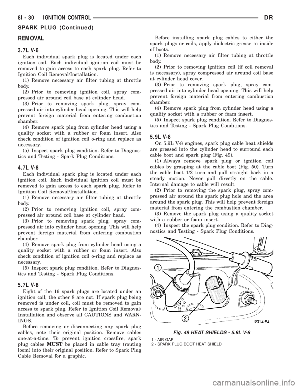
On 5.9L V-8 engines, spark plug cable heat shields
are pressed into the cylinder head to surround each
cable boot and spark plug (Fig. 49).
(1) Always remove spark plug or ignition coil
cables by grasping at the cable boot (Fig. 50). Turn
the cable boot 1/2 turn and pull straight back in a
steady motion. Never pull directly on the cable.
Internal damage to cable will result.
(2) Prior to removing the spark plug, spray com-
pressed air around the spark plug hole and the area
around the spark plug. This will help prevent foreign
material from entering the combustion chamber.
(3) Remove the spark plug using a quality socket
with a rubber or foam insert.
(4) Inspect the spark plug condition. Refer to Diag-
nostics and Testing - Spark Plug Conditions.
Fig. 49 HEAT SHIELDS - 5.9L V-8
1 - AIR GAP
2 - SPARK PLUG BOOT HEAT SHIELD
8I - 30 IGNITION CONTROLDR
SPARK PLUG (Continued)
Page 489 of 2895
4.7L V-8
CAUTION: The 4.7L V±8 engine is equipped with
copper core ground electrode spark plugs. They
must be replaced with the same type/number spark
plug as the original. If another spark plug is substi-
tuted, pre-ignition will result.
Special care should be taken when installing spark
plugs into the cylinder head spark plug wells. Be
sure the plugs do not drop into the plug wells as elec-
trodes can be damaged.
Always tighten spark plugs to the specified torque.
Over tightening can cause distortion resulting in a
change in the spark plug gap or a cracked porcelain
insulator.
(1) Start the spark plug into the cylinder head by
hand to avoid cross threading.
(2) Tighten spark plugs. Refer to torque specifica-
tions.
(3) Before installing ignition coil(s), check condi-
tion of coil o-ring and replace as necessary. To aid in
coil installation, apply silicone to coil o-ring.
(4) Install ignition coil(s). Refer to Ignition Coil
Removal/Installation.
5.7L V-8
(1) Special care should be taken when installing
spark plugs into the cylinder head spark plug wells.
Be sure the plugs do not drop into the plug wells as
electrodes can be damaged.
(2) Start the spark plug into cylinder head by
hand to avoid cross threading aluminum threads. To
aid in installation, attach a piece of rubber hose, or
an old spark plug boot to spark plug.
(3) The 5.7L V-8 is equipped with torque critical
design spark plugs. Do not exceed 15 ft. lbs. torque.
Tighten spark plugs. Refer to torque specifications.
(4) Before installing spark plug cables to either the
spark plugs or coils, apply dielectric grease to inside
of boots.
(5) To prevent ignition crossfire, spark plug cables
MUSTbe placed in cable tray (routing loom) into
their original position. Refer to Spark Plug Cable
Removal for a graphic.
(6) Install ignition coil(s) to necessary spark plugs.
Refer to Ignition Coil Installation.
(7) Install spark plug cables to remaining spark
plugs. Remember to apply dielectric grease to inside
of boots.
5.9L V-8
Special care should be taken when installing spark
plugs into the cylinder head spark plug wells. Be
sure the plugs do not drop into the plug wells as elec-
trodes can be damaged.
Always tighten spark plugs to the specified torque.
Over tightening can cause distortion resulting in a
change in the spark plug gap or a cracked porcelain
insulator.
When replacing the spark plug and ignition coil
cables, route the cables correctly and secure them in
the appropriate retainers. Failure to route the cables
properly can cause the radio to reproduce ignition
noise. It could cause cross ignition of the spark plugs
or short circuit the cables to ground.
(1) Start the spark plug into the cylinder head by
hand to avoid cross threading.
(2) Tighten spark plugs. Refer to torque specifica-
tions.
(3) Install spark plug cables to spark plugs. On
5.9L V-8 engines, spark plug cable heat shields are
pressed into the cylinder head to surround each
spark plug cable boot and spark plug (Fig. 53). These
shields protect the spark plug boots from damage
(due to intense engine heat generated by the exhaust
manifolds) and should not be removed. After the
spark plug cable has been installed, the lip of the
cable boot should have a small air gap to the top of
the heat shield (Fig. 53).
8.0L V-10
Special care should be taken when installing spark
plugs into the cylinder head spark plug wells. Be
sure the plugs do not drop into the plug wells as elec-
trodes can be damaged.
Always tighten spark plugs to the specified torque.
Over tightening can cause distortion resulting in a
change in the spark plug gap or a cracked porcelain
insulator.
When replacing the spark plug and ignition coil
cables, route the cables correctly and secure them in
the appropriate retainers. Failure to route the cables
properly can cause the radio to reproduce ignition
noise. It could cause cross ignition of the spark plugs
or short circuit the cables to ground.
(1) Start the spark plug into the cylinder head by
hand to avoid cross threading.
(2) Tighten spark plugs. Refer to torque specifica-
tions.
(3) Install spark plug cables to spark plugs.
8I - 32 IGNITION CONTROLDR
SPARK PLUG (Continued)