Engine Intake Manifold DODGE RAM 2003 Service Repair Manual
[x] Cancel search | Manufacturer: DODGE, Model Year: 2003, Model line: RAM, Model: DODGE RAM 2003Pages: 2895, PDF Size: 83.15 MB
Page 1733 of 2895
(2) Install and tighten two mounting bolts (screws)
to 7 N´m (60 in. lbs.) torque.
(3) Install electrical connector.
(4) Install air resonator to throttle body.
5.7L V-8
The IAC motor is not serviceable on the 5.7L V-8
engine.
5.9L V-8
The IAC motor is located on the back of the throt-
tle body (Fig. 22).
(1) Install IAC motor to throttle body.
(2) Install and tighten two mounting bolts (screws)
to 7 N´m (60 in. lbs.) torque.
(3) Install electrical connector.
(4) Install air resonator to throttle body.
8.0L V-10
The IAC motor is located on the back of the throt-
tle body (Fig. 23).
(1) Install IAC motor to throttle body.
(2) Install and tighten two mounting bolts (screws)
to 7 N´m (60 in. lbs.) torque.
(3) Install electrical connector.
(4) Install air cleaner housing to throttle body.
(5) Install 4 air cleaner housing mounting nuts.
Tighten nuts to 11 N´m (96 in. lbs.) torque.
(6) Install air cleaner housing cover.
INTAKE AIR TEMPERATURE
SENSOR
DESCRIPTION
The 2±wire Intake Manifold Air Temperature (IAT)
sensor is installed in the intake manifold with the
sensor element extending into the air stream.
The IAT sensor is a two-wire Negative Thermal
Coefficient (NTC) sensor. Meaning, as intake mani-
fold temperature increases, resistance (voltage) in the
sensor decreases. As temperature decreases, resis-
tance (voltage) in the sensor increases.
OPERATION
The IAT sensor provides an input voltage to the
Powertrain Control Module (PCM) indicating the
density of the air entering the intake manifold based
upon intake manifold temperature. At key-on, a
5±volt power circuit is supplied to the sensor from
the PCM. The sensor is grounded at the PCM
through a low-noise, sensor-return circuit.
The PCM uses this input to calculate the following:
²Injector pulse-width²Adjustment of spark timing (to help prevent
spark knock with high intake manifold air-charge
temperatures)
The resistance values of the IAT sensor is the same
as for the Engine Coolant Temperature (ECT) sensor.
REMOVAL
3.7L V-6
The intake manifold air temperature (IAT) sensor
is installed into the left side of intake manifold ple-
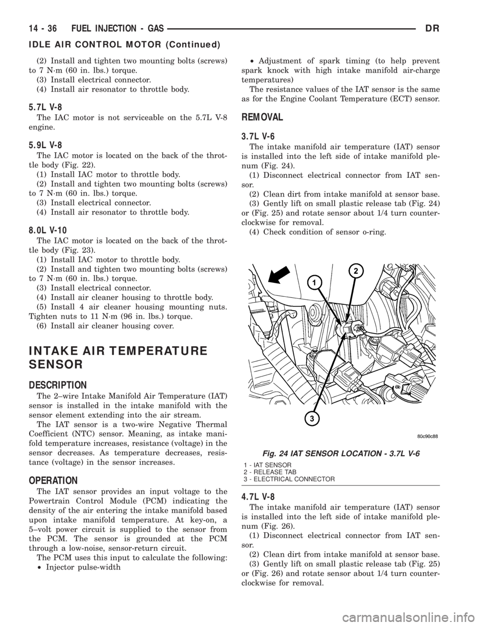
num (Fig. 24).
(1) Disconnect electrical connector from IAT sen-
sor.
(2) Clean dirt from intake manifold at sensor base.
(3) Gently lift on small plastic release tab (Fig. 24)
or (Fig. 25) and rotate sensor about 1/4 turn counter-
clockwise for removal.
(4) Check condition of sensor o-ring.
4.7L V-8
The intake manifold air temperature (IAT) sensor
is installed into the left side of intake manifold ple-
num (Fig. 26).
(1) Disconnect electrical connector from IAT sen-
sor.
(2) Clean dirt from intake manifold at sensor base.
(3) Gently lift on small plastic release tab (Fig. 25)
or (Fig. 26) and rotate sensor about 1/4 turn counter-
clockwise for removal.
Fig. 24 IAT SENSOR LOCATION - 3.7L V-6
1 - IAT SENSOR
2 - RELEASE TAB
3 - ELECTRICAL CONNECTOR
14 - 36 FUEL INJECTION - GASDR
IDLE AIR CONTROL MOTOR (Continued)
Page 1736 of 2895
(1) Install sensor to intake manifold. Tighten to
12±15 N´m (110±130 in. lbs.) torque.
(2) Install electrical connector.
MAP SENSOR
DESCRIPTION
3.7L V-6
The Manifold Absolute Pressure (MAP) sensor is
mounted into the front of the intake manifold with 2
screws.
4.7L V-8
The Manifold Absolute Pressure (MAP) sensor is
mounted into the front of the intake manifold with 2
screws.
5.7L V-8
The Manifold Absolute Pressure (MAP) sensor is
mounted to the front of the intake manifold air ple-
num box.
5.9L V-8
The Manifold Absolute Pressure (MAP) sensor is
mounted to the front of the throttle body with 2
screws.
8.0L V-10
The Manifold Absolute Pressure (MAP) sensor is
mounted into the right side of the intake manifold.
OPERATION
The MAP sensor is used as an input to the Power-
train Control Module (PCM). It contains a silicon
based sensing unit to provide data on the manifold
vacuum that draws the air/fuel mixture into the com-
bustion chamber. The PCM requires this information
to determine injector pulse width and spark advance.
When manifold absolute pressure (MAP) equals
Barometric pressure, the pulse width will be at max-
imum.
A 5 volt reference is supplied from the PCM and
returns a voltage signal to the PCM that reflects
manifold pressure. The zero pressure reading is 0.5V
and full scale is 4.5V. For a pressure swing of 0±15
psi, the voltage changes 4.0V. To operate the sensor,
it is supplied a regulated 4.8 to 5.1 volts. Ground is
provided through the low-noise, sensor return circuit
at the PCM.
The MAP sensor input is the number one contrib-
utor to fuel injector pulse width. The most important
function of the MAP sensor is to determine baromet-
ric pressure. The PCM needs to know if the vehicle is
at sea level or at a higher altitude, because the airdensity changes with altitude. It will also help to cor-
rect for varying barometric pressure. Barometric
pressure and altitude have a direct inverse correla-
tion; as altitude goes up, barometric goes down. At
key-on, the PCM powers up and looks at MAP volt-
age, and based upon the voltage it sees, it knows the
current barometric pressure (relative to altitude).
Once the engine starts, the PCM looks at the voltage
again, continuously every 12 milliseconds, and com-
pares the current voltage to what it was at key-on.
The difference between current voltage and what it
was at key-on, is manifold vacuum.
During key-on (engine not running) the sensor
reads (updates) barometric pressure. A normal range
can be obtained by monitoring a known good sensor.
As the altitude increases, the air becomes thinner
(less oxygen). If a vehicle is started and driven to a
very different altitude than where it was at key-on,
the barometric pressure needs to be updated. Any
time the PCM sees Wide Open Throttle (WOT), based
upon Throttle Position Sensor (TPS) angle and RPM,
it will update barometric pressure in the MAP mem-
ory cell. With periodic updates, the PCM can make
its calculations more effectively.
The PCM uses the MAP sensor input to aid in cal-
culating the following:
²Manifold pressure
²Barometric pressure
²Engine load
²Injector pulse-width
²Spark-advance programs
²Shift-point strategies (certain automatic trans-
missions only)
²Idle speed
²Decel fuel shutoff
The MAP sensor signal is provided from a single
piezoresistive element located in the center of a dia-
phragm. The element and diaphragm are both made
of silicone. As manifold pressure changes, the dia-
phragm moves causing the element to deflect, which
stresses the silicone. When silicone is exposed to
stress, its resistance changes. As manifold vacuum
increases, the MAP sensor input voltage decreases
proportionally. The sensor also contains electronics
that condition the signal and provide temperature
compensation.
The PCM recognizes a decrease in manifold pres-
sure by monitoring a decrease in voltage from the
reading stored in the barometric pressure memory
cell. The MAP sensor is a linear sensor; meaning as
pressure changes, voltage changes proportionately.
The range of voltage output from the sensor is usu-
ally between 4.6 volts at sea level to as low as 0.3
volts at 26 in. of Hg. Barometric pressure is the pres-
sure exerted by the atmosphere upon an object. At
sea level on a standard day, no storm, barometric
DRFUEL INJECTION - GAS 14 - 39
INTAKE AIR TEMPERATURE SENSOR (Continued)
Page 1739 of 2895
INSTALLATION
3.7L V-6
The Manifold Absolute Pressure (MAP) sensor is
mounted into the front of the intake manifold (Fig.
31). An o-ring is used to seal the sensor to the intake
manifold (Fig. 32).
(1) Clean MAP sensor mounting hole at intake
manifold.
(2) Check MAP sensor o-ring seal for cuts or tears.
(3) Position sensor into manifold.(4) Install MAP sensor mounting bolts (screws).
Refer to Torque Specifications.
(5) Connect electrical connector.
4.7L V-8
The MAP sensor is located on the front of the
intake manifold (Fig. 33). An o-ring seals the sensor
to the intake manifold (Fig. 32).
(1) Clean MAP sensor mounting hole at intake
manifold.
(2) Check MAP sensor o-ring seal for cuts or tears.
(3) Position sensor into manifold.
(4) Install MAP sensor mounting bolts (screws).
Refer to Torque Specifications.
(5) Connect electrical connector.
5.7L V-8
The Manifold Absolute Pressure (MAP) sensor is
mounted to the front of the intake manifold air ple-
num box (Fig. 34).
(1) Clean MAP sensor mounting hole at intake
manifold.
(2) Check MAP sensor o-ring seal for cuts or tears.
(3) Position sensor into manifold.
(4) Rotate sensor 1/4 turn clockwise for installa-
tion.
(5) Connect electrical connector.
5.9L V-8
The MAP sensor is located on the front of the
throttle body (Fig. 36). An L-shaped rubber fitting is
used to connect the MAP sensor to throttle body (Fig.
37).
(1) Install rubber L-shaped fitting to MAP sensor.
(2) Position sensor to throttle body while guiding
rubber fitting over throttle body vacuum nipple.
(3) Install MAP sensor mounting bolts (screws).
Refer to Torque Specifications.
(4) Install air resonator box.
8.0L V-10
The MAP sensor is mounted into the right upper
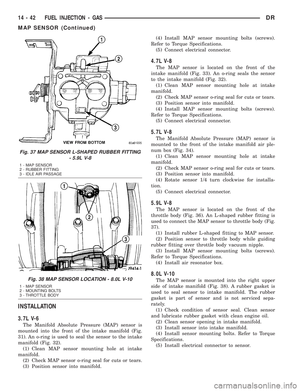
side of intake manifold (Fig. 38). A rubber gasket is
used to seal sensor to intake manifold. The rubber
gasket is part of sensor and is not serviced sepa-
rately.
(1) Check condition of sensor seal. Clean sensor
and lubricate rubber gasket with clean engine oil.
(2) Clean sensor opening in intake manifold.
(3) Install sensor into intake manifold.
(4) Install sensor mounting bolts. Refer to Torque
Specifications.
(5) Install electrical connector to sensor.
Fig. 37 MAP SENSOR L-SHAPED RUBBER FITTING
- 5.9L V-8
1 - MAP SENSOR
2 - RUBBER FITTING
3 - IDLE AIR PASSAGE
Fig. 38 MAP SENSOR LOCATION - 8.0L V-10
1 - MAP SENSOR
2 - MOUNTING BOLTS
3 - THROTTLE BODY
14 - 42 FUEL INJECTION - GASDR
MAP SENSOR (Continued)
Page 1742 of 2895
INSTALLATION
Threads of new oxygen sensors are factory coated
with anti-seize compound to aid in removal.DO
NOT add any additional anti-seize compound to
threads of a new oxygen sensor.
(1) Install O2S sensor. Tighten to 30 N´m (22 ft.
lbs.) torque.
(2) Connect O2S sensor wire connector.
(3) Lower vehicle.
THROTTLE BODY
DESCRIPTION
The throttle body is located on the intake manifold.
Fuel does not enter the intake manifold through the
throttle body. Fuel is sprayed into the manifold by
the fuel injectors.
OPERATION
Filtered air from the air cleaner enters the intake
manifold through the throttle body. The throttle body
contains an air control passage controlled by an Idle
Air Control (IAC) motor. The air control passage is
used to supply air for idle conditions. A throttle valve
(plate) is used to supply air for above idle conditions.
5.7L V-8 Engine:
The throttle body on the 5.7L engine is an electri-
cally controlled unit. A mechanical cable is not used
to connect the throttle body to the accelerator pedal.
The Accelerator Pedal Position Sensor (APPS) along
with inputs from other sensors sets the throttle blade
to pre-determined positions.
Except 5.7L V-8 Engine:
Certain sensors are attached to the throttle body.
The accelerator pedal cable, speed control cable and
transmission control cable (when equipped) are con-
nected to the throttle body linkage arm.
A (factory adjusted) set screw is used to mechani-
cally limit the position of the throttle body throttle
plate.Never attempt to adjust the engine idle
speed using this screw.All idle speed functions are
controlled by the PCM.
REMOVAL
3.7L V-6
A (factory adjusted) set screw is used to mechani-
cally limit the position of the throttle body throttle
plate.Never attempt to adjust the engine idle
speed using this screw.All idle speed functions are
controlled by the Powertrain Control Module (PCM).
(1) Remove air cleaner tube at throttle body.
(2) Disconnect throttle body electrical connectors
at IAC motor and TPS.(3) Remove all control cables from throttle body
(lever) arm. Refer to the Accelerator Pedal and Throt-
tle Cable section for removal/installation procedures.
(4) Disconnect necessary vacuum lines at throttle
body.
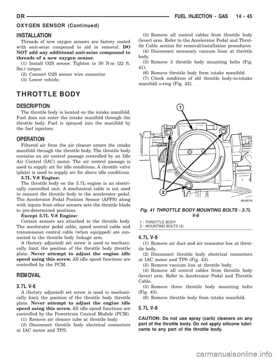
(5) Remove 3 throttle body mounting bolts (Fig.
41).
(6) Remove throttle body from intake manifold.
(7) Check condition of old throttle body-to-intake
manifold o-ring (Fig. 42).
4.7L V-8
(1) Remove air duct and air resonator box at throt-
tle body.
(2) Disconnect throttle body electrical connectors
at IAC motor and TPS (Fig. 43).
(3) Remove vacuum line at throttle body.
(4) Remove all control cables from throttle body
(lever) arm. Refer to Accelerator Pedal and Throttle
Cable.
(5) Remove three throttle body mounting bolts
(Fig. 43).
(6) Remove throttle body from intake manifold.
5.7L V-8
CAUTION: Do not use spray (carb) cleaners on any
part of the throttle body. Do not apply silicone lubri-
cants to any part of the throttle body.
Fig. 41 THROTTLE BODY MOUNTING BOLTS - 3.7L
V-6
1 - THROTTLE BODY
2 - MOUNTING BOLTS (3)
DRFUEL INJECTION - GAS 14 - 45
OXYGEN SENSOR (Continued)
Page 1743 of 2895
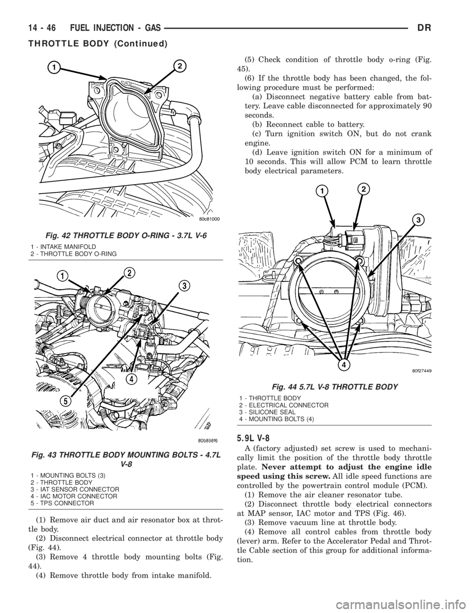
(1) Remove air duct and air resonator box at throt-
tle body.
(2) Disconnect electrical connector at throttle body
(Fig. 44).
(3) Remove 4 throttle body mounting bolts (Fig.
44).
(4) Remove throttle body from intake manifold.(5) Check condition of throttle body o-ring (Fig.
45).
(6) If the throttle body has been changed, the fol-
lowing procedure must be performed:
(a) Disconnect negative battery cable from bat-
tery. Leave cable disconnected for approximately 90
seconds.
(b) Reconnect cable to battery.
(c) Turn ignition switch ON, but do not crank
engine.
(d) Leave ignition switch ON for a minimum of
10 seconds. This will allow PCM to learn throttle
body electrical parameters.
5.9L V-8
A (factory adjusted) set screw is used to mechani-
cally limit the position of the throttle body throttle
plate.Never attempt to adjust the engine idle
speed using this screw.All idle speed functions are
controlled by the powertrain control module (PCM).
(1) Remove the air cleaner resonator tube.
(2) Disconnect throttle body electrical connectors
at MAP sensor, IAC motor and TPS (Fig. 46).
(3) Remove vacuum line at throttle body.
(4) Remove all control cables from throttle body
(lever) arm. Refer to the Accelerator Pedal and Throt-
tle Cable section of this group for additional informa-
tion.
Fig. 42 THROTTLE BODY O-RING - 3.7L V-6
1 - INTAKE MANIFOLD
2 - THROTTLE BODY O-RING
Fig. 43 THROTTLE BODY MOUNTING BOLTS - 4.7L
V-8
1 - MOUNTING BOLTS (3)
2 - THROTTLE BODY
3 - IAT SENSOR CONNECTOR
4 - IAC MOTOR CONNECTOR
5 - TPS CONNECTOR
Fig. 44 5.7L V-8 THROTTLE BODY
1 - THROTTLE BODY
2 - ELECTRICAL CONNECTOR
3 - SILICONE SEAL
4 - MOUNTING BOLTS (4)
14 - 46 FUEL INJECTION - GASDR
THROTTLE BODY (Continued)
Page 1744 of 2895
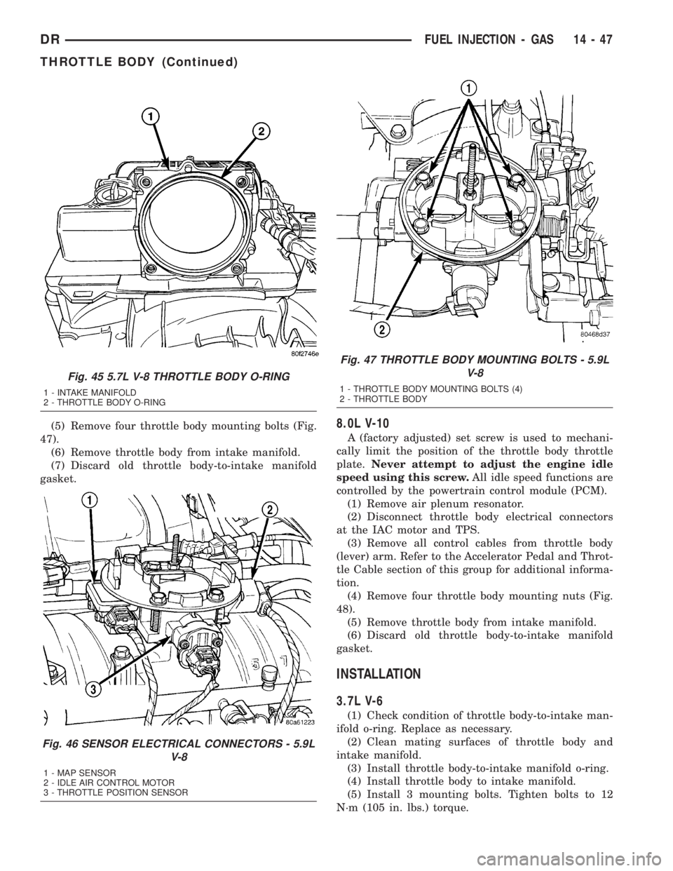
(5) Remove four throttle body mounting bolts (Fig.
47).
(6) Remove throttle body from intake manifold.
(7) Discard old throttle body-to-intake manifold
gasket.8.0L V-10
A (factory adjusted) set screw is used to mechani-
cally limit the position of the throttle body throttle
plate.Never attempt to adjust the engine idle
speed using this screw.All idle speed functions are
controlled by the powertrain control module (PCM).
(1) Remove air plenum resonator.
(2) Disconnect throttle body electrical connectors
at the IAC motor and TPS.
(3) Remove all control cables from throttle body
(lever) arm. Refer to the Accelerator Pedal and Throt-
tle Cable section of this group for additional informa-
tion.
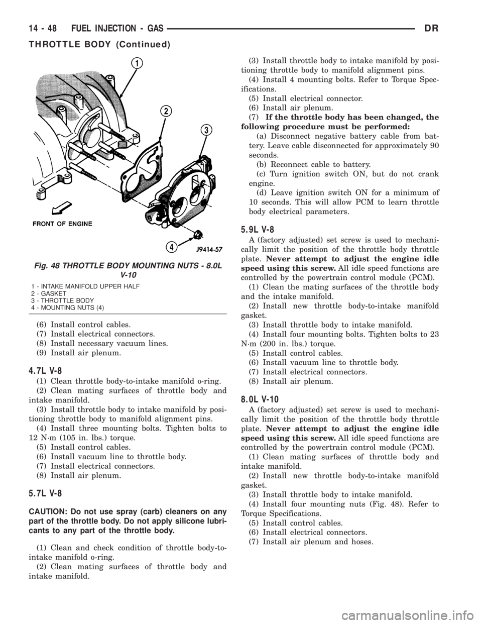
(4) Remove four throttle body mounting nuts (Fig.
48).
(5) Remove throttle body from intake manifold.
(6) Discard old throttle body-to-intake manifold
gasket.
INSTALLATION
3.7L V-6
(1) Check condition of throttle body-to-intake man-
ifold o-ring. Replace as necessary.
(2) Clean mating surfaces of throttle body and
intake manifold.
(3) Install throttle body-to-intake manifold o-ring.
(4) Install throttle body to intake manifold.
(5) Install 3 mounting bolts. Tighten bolts to 12
N´m (105 in. lbs.) torque.
Fig. 45 5.7L V-8 THROTTLE BODY O-RING
1 - INTAKE MANIFOLD
2 - THROTTLE BODY O-RING
Fig. 46 SENSOR ELECTRICAL CONNECTORS - 5.9L
V-8
1 - MAP SENSOR
2 - IDLE AIR CONTROL MOTOR
3 - THROTTLE POSITION SENSOR
Fig. 47 THROTTLE BODY MOUNTING BOLTS - 5.9L
V-8
1 - THROTTLE BODY MOUNTING BOLTS (4)
2 - THROTTLE BODY
DRFUEL INJECTION - GAS 14 - 47
THROTTLE BODY (Continued)
Page 1745 of 2895
(6) Install control cables.
(7) Install electrical connectors.
(8) Install necessary vacuum lines.
(9) Install air plenum.
4.7L V-8
(1) Clean throttle body-to-intake manifold o-ring.
(2) Clean mating surfaces of throttle body and
intake manifold.
(3) Install throttle body to intake manifold by posi-
tioning throttle body to manifold alignment pins.
(4) Install three mounting bolts. Tighten bolts to
12 N´m (105 in. lbs.) torque.
(5) Install control cables.
(6) Install vacuum line to throttle body.
(7) Install electrical connectors.
(8) Install air plenum.
5.7L V-8
CAUTION: Do not use spray (carb) cleaners on any
part of the throttle body. Do not apply silicone lubri-
cants to any part of the throttle body.
(1) Clean and check condition of throttle body-to-
intake manifold o-ring.
(2) Clean mating surfaces of throttle body and
intake manifold.(3) Install throttle body to intake manifold by posi-
tioning throttle body to manifold alignment pins.
(4) Install 4 mounting bolts. Refer to Torque Spec-
ifications.
(5) Install electrical connector.
(6) Install air plenum.
(7)If the throttle body has been changed, the
following procedure must be performed:
(a) Disconnect negative battery cable from bat-
tery. Leave cable disconnected for approximately 90
seconds.
(b) Reconnect cable to battery.
(c) Turn ignition switch ON, but do not crank
engine.
(d) Leave ignition switch ON for a minimum of
10 seconds. This will allow PCM to learn throttle
body electrical parameters.
5.9L V-8
A (factory adjusted) set screw is used to mechani-
cally limit the position of the throttle body throttle
plate.Never attempt to adjust the engine idle
speed using this screw.All idle speed functions are
controlled by the powertrain control module (PCM).
(1) Clean the mating surfaces of the throttle body
and the intake manifold.
(2) Install new throttle body-to-intake manifold
gasket.
(3) Install throttle body to intake manifold.
(4) Install four mounting bolts. Tighten bolts to 23
N´m (200 in. lbs.) torque.
(5) Install control cables.
(6) Install vacuum line to throttle body.
(7) Install electrical connectors.
(8) Install air plenum.
8.0L V-10
A (factory adjusted) set screw is used to mechani-
cally limit the position of the throttle body throttle
plate.Never attempt to adjust the engine idle
speed using this screw.All idle speed functions are
controlled by the powertrain control module (PCM).
(1) Clean mating surfaces of throttle body and
intake manifold.
(2) Install new throttle body-to-intake manifold
gasket.
(3) Install throttle body to intake manifold.
(4) Install four mounting nuts (Fig. 48). Refer to
Torque Specifications.
(5) Install control cables.
(6) Install electrical connectors.
(7) Install air plenum and hoses.
Fig. 48 THROTTLE BODY MOUNTING NUTS - 8.0L
V-10
1 - INTAKE MANIFOLD UPPER HALF
2 - GASKET
3 - THROTTLE BODY
4 - MOUNTING NUTS (4)
14 - 48 FUEL INJECTION - GASDR
THROTTLE BODY (Continued)
Page 1755 of 2895
STANDARD PROCEDURES - CLEANING FUEL
SYSTEM PARTS
CAUTION: Cleanliness cannot be overemphasized
when handling or replacing diesel fuel system com-
ponents. This especially includes the fuel injectors,
high-pressure fuel lines and fuel injection pump.
Very tight tolerances are used with these parts. Dirt
contamination could cause rapid part wear and pos-
sible plugging of fuel injector nozzle tip holes. This
in turn could lead to possible engine misfire.Always wash/clean any fuel system component
thoroughly before disassembly and then air dry.
Cap or cover any open part after disassembly.
Before assembly, examine each part for dirt, grease
or other contaminants and clean if necessary. When
installing new parts, lubricate them with clean
engine oil or clean diesel fuel only.
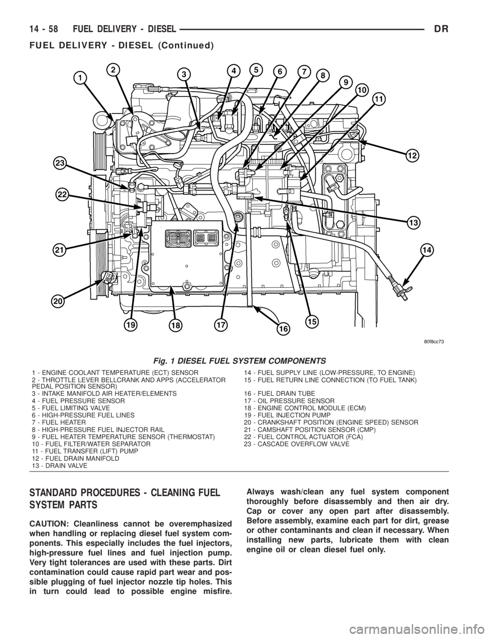
Fig. 1 DIESEL FUEL SYSTEM COMPONENTS
1 - ENGINE COOLANT TEMPERATURE (ECT) SENSOR 14 - FUEL SUPPLY LINE (LOW-PRESSURE, TO ENGINE)
2 - THROTTLE LEVER BELLCRANK AND APPS (ACCELERATOR
PEDAL POSITION SENSOR)15 - FUEL RETURN LINE CONNECTION (TO FUEL TANK)
3 - INTAKE MANIFOLD AIR HEATER/ELEMENTS 16 - FUEL DRAIN TUBE
4 - FUEL PRESSURE SENSOR 17 - OIL PRESSURE SENSOR
5 - FUEL LIMITING VALVE 18 - ENGINE CONTROL MODULE (ECM)
6 - HIGH-PRESSURE FUEL LINES 19 - FUEL INJECTION PUMP
7 - FUEL HEATER 20 - CRANKSHAFT POSITION (ENGINE SPEED) SENSOR
8 - HIGH-PRESSURE FUEL INJECTOR RAIL 21 - CAMSHAFT POSITION SENSOR (CMP)
9 - FUEL HEATER TEMPERATURE SENSOR (THERMOSTAT) 22 - FUEL CONTROL ACTUATOR (FCA)
10 - FUEL FILTER/WATER SEPARATOR 23 - CASCADE OVERFLOW VALVE
11 - FUEL TRANSFER (LIFT) PUMP
12 - FUEL DRAIN MANIFOLD
13 - DRAIN VALVE
14 - 58 FUEL DELIVERY - DIESELDR
FUEL DELIVERY - DIESEL (Continued)
Page 1762 of 2895
pump. The Fuel Pump/Gear Pump is a low-pressure
pump and produce pressures ranging from 551.5 kpa
(80 psi) to 1241 kpa (180) psi. Fuel then enters the
fuel injection pump. Low pressure fuel is then sup-
plied to the FAC (Fuel Control Actuator).
The FAC is an electronically controlled solenoid
valve. The ECM controls the amount of fuel that
enters the high-pressure pumping chambers by open-
ing and closing the FAC based on a demanded fuel
pressure. The FPS (Fuel Pressure Sensor) on the fuel
rail provides the actual fuel pressure. When the
actuator is opened, the maximum amount of fuel is
being supplied to the fuel injection pump. Any fuel
that does not enter the injection pump is directed to
the overflow valve. The overflow valve regulates how
much excess fuel is used for lubrication of the pump
and how much is returned to the tank through the
drain manifold.
Fuel entering the injection pump is pressurized to
between 300 - 1600 bar by three radial pumping
chambers. The pressurized fuel is then supplied to
the fuel rail.
DIAGNOSIS AND TESTING - FUEL INJECTION
PUMP TIMING
With the Bosch injection pump, there are no
mechanical adjustments needed or necessary to
accomplish fuel injection timing. All timing and fuel
adjustments are electrically made by the engine
mounted Engine Control Module (ECM).
REMOVAL
CAUTION: Cleanliness cannot be overemphasized
when handling or replacing diesel fuel system com-
ponents. This especially includes the fuel injectors,
high-pressure fuel lines and fuel injection pump.
Very tight tolerances are used with these parts. Dirt
contamination could cause rapid part wear and pos-
sible plugging of fuel injector nozzle tip holes. This
in turn could lead to possible engine misfire.
Always wash/clean any fuel system component
thoroughly before disassembly and then air dry.
Cap or cover any open part after disassembly.
Before assembly, examine each part for dirt, grease
or other contaminants and clean if necessary. When
installing new parts, lubricate them with clean
engine oil or clean diesel fuel only.
(1) Disconnect both negative battery cables at both
batteries. Cover and isolate ends of both cables.
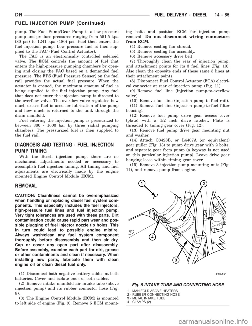
(2) Remove intake manifold air intake tube (above
injection pump) and its rubber connector hose (Fig.
8).
(3) The Engine Control Module (ECM) is mounted
to left side of engine (Fig. 9). Remove 5 ECM mount-ing bolts and position ECM for injection pump
removal.Do not disconnect wiring connectors
from ECM.
(4) Remove cooling fan shroud.
(5) Remove cooling fan assembly.
(6) Remove accessory drive belt.
(7) Thoroughly clean the rear of injection pump,
and attachment points for its 3 fuel lines (Fig. 10).
Also clean the opposite ends of these same 3 lines at
their attachment points.
(8) Disconnect Fuel Control Actuator (FCA) electri-
cal connector at rear of injection pump (Fig. 11).
(9) Remove fuel line (injection pump-to-overflow
valve).
(10) Remove fuel line (injection pump-to-fuel rail).
(11) Remove fuel line (injection pump-to-fuel filter
housing).
(12) Remove fuel pump drive gear access cover
(plate) with a 1/2 inch drive ratchet. Plate is
threaded to timing gear cover (Fig. 12).
(13) Remove fuel pump drive gear mounting nut
and washer.
(14) Attach C3428B, or L4407A (or equivalent)
gear puller (Fig. 13) to pump drive gear with 2 bolts,
and separate gear from pump (a keyway is not used
on this particular injection pump). Leave drive gear
hanging loose within timing gear cover.
(15) Remove 3 injection pump mounting nuts (Fig.
14), and remove pump from engine.
Fig. 8 INTAKE TUBE AND CONNECTING HOSE
1 - MANIFOLD ABOVE HEATERS
2 - RUBBER CONNECTING HOSE
3 - METAL INTAKE TUBE
4 - CLAMPS (2)
DRFUEL DELIVERY - DIESEL 14 - 65
FUEL INJECTION PUMP (Continued)
Page 1765 of 2895
(4) Apply clean engine oilto injection pump
o-ring only.
The machined tapers on both injection pump
shaft and injection pump gear must be abso-
lutely dry, clean and free of any dirt or oil film.
This will ensure proper gear-to-shaft tighten-
ing.
(5) Clean pump gear and pump shaft at machined
tapers with an evaporative type cleaner such as
brake cleaner.
(6) Position injection pump to mounting flange on
gear cover while aligning injection pump shaft
through back of injection pump gear.
(7) After pump is positioned flat to mounting
flange, install 3 pump mounting nuts and tighten
finger tight only.Do not attempt a final tightening
at this time.Do not attempt to tighten (pull)
pump to gear cover using mounting nuts. Dam-
age to pump or gear cover may occur. The
pump must be positioned flat to its mounting
flange before attempting to tighten 3 mounting
nuts.
(8) To prevent damage or cracking of components,
install and tighten nuts in the following sequence:
(a) Install injection pump shaft washer and nut
to pump shaft. Tighten nutfinger tight only.
(b) Do preliminary (light) tightening of injection
pump shaft nut.
(c) Tighten 3 injection pump mounting nuts to 8
N´m (70.8 in. lbs.).
(d) Do a final tightening of pump shaft nut to
105 N´m (77 ft. lbs.).
(9) Install drive gear access cover (plate) using a
1/2 inch drive ratchet. Plate is threaded to timing
gear cover.
(10) Install Engine Control Module (ECM) to left
side of engine.
(11) Install fuel line (injection pump-to-overflow
valve). Tighten bolts to 24 N´m (17 ft. lbs.) torque.
(12) Install fuel line (injection pump-to-fuel rail).
Tighten to 24 N´m (17 ft. lbs.) torque.
(13) Install fuel line (injection pump-to-fuel filter
housing). Tighten to 24 N´m (17 ft. lbs.) torque.
(14) Connect Fuel Control Actuator (FCA) electri-
cal connector to rear of injection pump.
(15) Install intake manifold air intake tube (above
injection pump). Tighten clamps.
(16) Install accessory drive belt.
(17) Install cooling fan shroud.
(18) Install cooling fan assembly.
(19) Connect both negative battery cables to both
batteries.
(20) Check system for fuel or engine oil leaks.FUEL LEVEL SENDING UNIT /
SENSOR
DESCRIPTION
The fuel gauge sending unit (fuel level sensor) is
attached to the side of the fuel tank module. The
sending unit consists of a float, an arm, and a vari-
able resistor track (card).
OPERATION
The fuel tank module on diesel powered models
has 3 different circuits (wires). Two of these circuits
are used at the fuel gauge sending unit for fuel
gauge operation. The other wire is used for a ground.
The diesel engine does not have a fuel tank module
mounted electric fuel pump. The electric fuel pump
(fuel transfer pump) is mounted to the engine.
For Fuel Gauge Operation:A constant input
voltage source of about 12 volts (battery voltage) is
supplied to the resistor track on the fuel gauge send-
ing unit. This is fed directly from the Powertrain
Control Module (PCM).NOTE: For diagnostic pur-
poses, this 12V power source can only be veri-
fied with the circuit opened (fuel tank module
electrical connector unplugged). With the con-
nectors plugged, output voltages will vary from
about .6 volts at FULL, to about 7.0 volts at
EMPTY.The resistor track is used to vary the volt-
age (resistance) depending on fuel tank float level. As
fuel level increases, the float and arm move up,
which decreases voltage. As fuel level decreases, the
float and arm move down, which increases voltage.
The varied voltage signal is returned back to the
ECM through the sensor return circuit.
Both of the electrical circuits between the fuel
gauge sending unit and the ECM are hard-wired (not
multi-plexed). After the voltage signal is sent from
the resistor track, and back to the ECM, the ECM
will interpret the resistance (voltage) data and send
a message across the multi-plex bus circuits to the
instrument panel cluster. Here it is translated into
the appropriate fuel gauge level reading. Refer to
Instrument Panel for additional information.
REMOVAL
REMOVAL/INSTALLATION
For diesel removal and installation procedures,
refer to the gas section of Fuel System/Fuel Delivery.
See Fuel Level Sending Unit/Sensor Removal/Instal-
lation.
14 - 68 FUEL DELIVERY - DIESELDR
FUEL INJECTION PUMP (Continued)