Engine Intake Manifold DODGE RAM 2003 Service Repair Manual
[x] Cancel search | Manufacturer: DODGE, Model Year: 2003, Model line: RAM, Model: DODGE RAM 2003Pages: 2895, PDF Size: 83.15 MB
Page 1790 of 2895
Refer to Powertrain Diagnostic Procedures for an
electrical operation and complete description of the
intake heaters, including pre-heat and post-heat
cycles.
REMOVAL
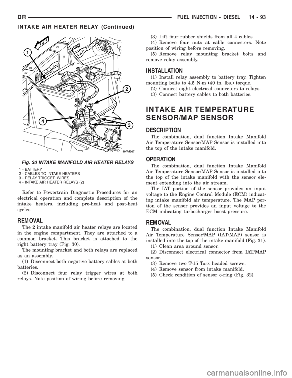
The 2 intake manifold air heater relays are located
in the engine compartment. They are attached to a
common bracket. This bracket is attached to the
right battery tray (Fig. 30).
The mounting bracket and both relays are replaced
as an assembly.
(1) Disconnect both negative battery cables at both
batteries.
(2) Disconnect four relay trigger wires at both
relays. Note position of wiring before removing.(3) Lift four rubber shields from all 4 cables.
(4) Remove four nuts at cable connectors. Note
position of wiring before removing.
(5) Remove relay mounting bracket bolts and
remove relay assembly.
INSTALLATION
(1) Install relay assembly to battery tray. Tighten
mounting bolts to 4.5 N´m (40 in. lbs.) torque.
(2) Connect eight electrical connectors to relays.
(3) Connect battery cables to both batteries.
INTAKE AIR TEMPERATURE
SENSOR/MAP SENSOR
DESCRIPTION
The combination, dual function Intake Manifold
Air Temperature Sensor/MAP Sensor is installed into
the top of the intake manifold.
OPERATION
The combination, dual function Intake Manifold
Air Temperature Sensor/MAP Sensor is installed into
the top of the intake manifold with the sensor ele-
ment extending into the air stream.
The IAT portion of the sensor provides an input
voltage to the Engine Control Module (ECM) indicat-
ing intake manifold air temperature. The MAP por-
tion of the sensor provides an input voltage to the
ECM indicating turbocharger boost pressure.
REMOVAL
The combination, dual function Intake Manifold
Air Temperature Sensor/MAP (IAT/MAP) sensor is
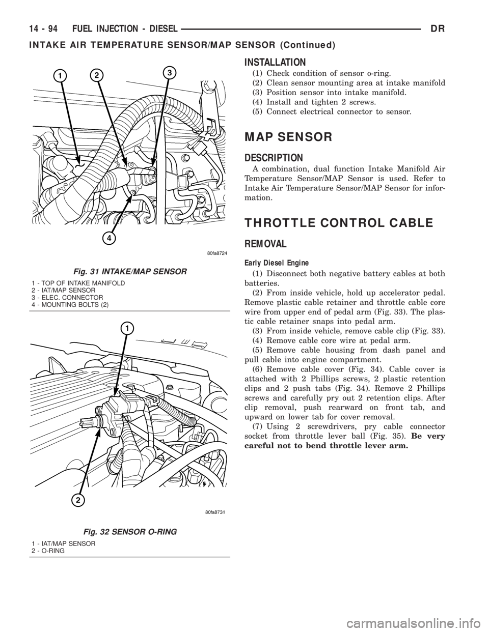
installed into the top of the intake manifold (Fig. 31).
(1) Clean area around sensor.
(2) Disconnect electrical connector from IAT/MAP
sensor.
(3) Remove two T-15 Torx headed screws.
(4) Remove sensor from intake manifold.
(5) Check condition of sensor o-ring (Fig. 32).
Fig. 30 INTAKE MANIFOLD AIR HEATER RELAYS
1 - BATTERY
2 - CABLES TO INTAKE HEATERS
3 - RELAY TRIGGER WIRES
4 - INTAKE AIR HEATER RELAYS (2)
DRFUEL INJECTION - DIESEL 14 - 93
INTAKE AIR HEATER RELAY (Continued)
Page 1791 of 2895
INSTALLATION
(1) Check condition of sensor o-ring.
(2) Clean sensor mounting area at intake manifold
(3) Position sensor into intake manifold.
(4) Install and tighten 2 screws.
(5) Connect electrical connector to sensor.
MAP SENSOR
DESCRIPTION
A combination, dual function Intake Manifold Air
Temperature Sensor/MAP Sensor is used. Refer to
Intake Air Temperature Sensor/MAP Sensor for infor-
mation.
THROTTLE CONTROL CABLE
REMOVAL
Early Diesel Engine
(1) Disconnect both negative battery cables at both
batteries.
(2) From inside vehicle, hold up accelerator pedal.
Remove plastic cable retainer and throttle cable core
wire from upper end of pedal arm (Fig. 33). The plas-
tic cable retainer snaps into pedal arm.
(3) From inside vehicle, remove cable clip (Fig. 33).
(4) Remove cable core wire at pedal arm.
(5) Remove cable housing from dash panel and
pull cable into engine compartment.
(6) Remove cable cover (Fig. 34). Cable cover is
attached with 2 Phillips screws, 2 plastic retention
clips and 2 push tabs (Fig. 34). Remove 2 Phillips
screws and carefully pry out 2 retention clips. After
clip removal, push rearward on front tab, and
upward on lower tab for cover removal.
(7) Using 2 screwdrivers, pry cable connector
socket from throttle lever ball (Fig. 35).Be very
careful not to bend throttle lever arm.
Fig. 31 INTAKE/MAP SENSOR
1 - TOP OF INTAKE MANIFOLD
2 - IAT/MAP SENSOR
3 - ELEC. CONNECTOR
4 - MOUNTING BOLTS (2)
Fig. 32 SENSOR O-RING
1 - IAT/MAP SENSOR
2 - O-RING
14 - 94 FUEL INJECTION - DIESELDR
INTAKE AIR TEMPERATURE SENSOR/MAP SENSOR (Continued)
Page 2777 of 2895
coil. To maintain minimum evaporator temperature
and prevent evaporator freezing, the A/C Fin Probe
which is located in the evaporator cycles the com-
pressor clutch by sending an A/C request to the
JTEC which in turn processes this piece of informa-
tion and if all conditions are met cycles the compres-
sor clutch.
OPERATION - REFRIGERANT SYSTEM SERVICE
PORT
The low pressure service port is located on the suc-
tion refrigerant line, near the accumulator. The high
pressure service port is located on the liquid line at
the passenger side of the engine compartment, near
the condenser.
Each of the service ports has a threaded plastic
protective cap installed over it from the factory. After
servicing the refrigerant system, always reinstall
both of the service port caps.
DIAGNOSIS AND TESTING
DIAGNOSIS AND TESTING - A/C
PERFORMANCE
The air conditioning system is designed to provide
the passenger compartment with low temperature
and low humidity air. The evaporator, located in the
HVAC housing on the dash panel below the instru-
ment panel, is cooled to temperatures near the freez-
ing point. As warm damp air passes through the
cooled evaporator, the air transfers its heat to the
refrigerant in the evaporator and the moisture in the
air condenses on the evaporator fins. During periods
of high heat and humidity, an air conditioning sys-
tem will be more effective in the Recirculation Mode.
With the system in the Recirculation Mode, only air
from the passenger compartment passes through the
evaporator. As the passenger compartment air dehu-
midifies, the air conditioning system performance
levels improve.
Humidity has an important bearing on the temper-
ature of the air delivered to the interior of the vehi-
cle. It is important to understand the effect that
humidity has on the performance of the air condition-
ing system. When humidity is high, the evaporator
has to perform a double duty. It must lower the air
temperature, and it must lower the temperature of
the moisture in the air that condenses on the evapo-
rator fins. Condensing the moisture in the air trans-
fers heat energy into the evaporator fins and tubing.
This reduces the amount of heat the evaporator can
absorb from the air. High humidity greatly reduces
the ability of the evaporator to lower the temperature
of the air.
However, evaporator capacity used to reduce the
amount of moisture in the air is not wasted. Remov-
ing some of the moisture out of the air entering the
vehicle adds to the comfort of the passengers.
Although, an owner may expect too much from the
air conditioning system on humid days. A perfor-
mance test is the best way to determine whether the
system is performing up to standard. This test also
provides valuable clues as to the possible cause of
trouble with the air conditioning system.
Before proceeding, (Refer to 24 - HEATING & AIR
CONDITIONING/PLUMBING - WARNING) and
(Refer to 24 - HEATING & AIR CONDITIONING/
PLUMBING - CAUTION). The air temperature in
the test room and in the vehicle must be a minimum
of 21É C (70É F) for this test.
(1) Connect a tachometer and a manifold gauge set
or A/C recycling/charging station.
(2) Set the A/C Heater mode control switch knob in
the Recirculation Mode position, the temperature
control knob in the full cool position, and the blower
motor switch knob in the highest speed position.
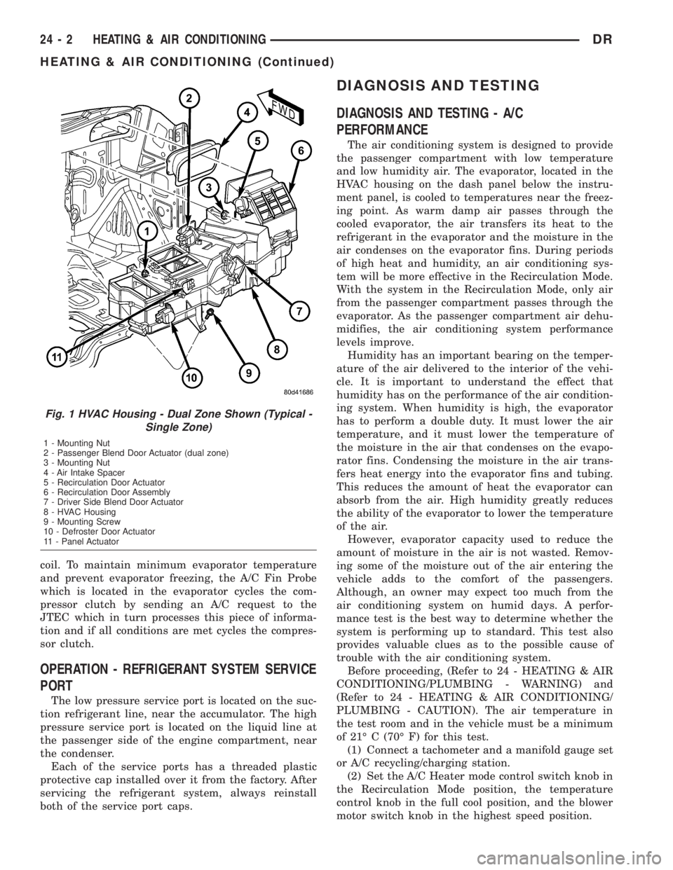
Fig. 1 HVAC Housing - Dual Zone Shown (Typical -
Single Zone)
1 - Mounting Nut
2 - Passenger Blend Door Actuator (dual zone)
3 - Mounting Nut
4 - Air Intake Spacer
5 - Recirculation Door Actuator
6 - Recirculation Door Assembly
7 - Driver Side Blend Door Actuator
8 - HVAC Housing
9 - Mounting Screw
10 - Defroster Door Actuator
11 - Panel Actuator
24 - 2 HEATING & AIR CONDITIONINGDR
HEATING & AIR CONDITIONING (Continued)
Page 2839 of 2895
EVAPORATIVE EMISSIONS
TABLE OF CONTENTS
page page
EVAPORATIVE EMISSIONS
DESCRIPTION - EVAP SYSTEM............10
SPECIFICATIONS
TORQUE - EVAP SYSTEM..............12
CCV HOSE
DESCRIPTION - 8.0L V-10................12
OPERATION - 8.0L V-10..................12
EVAP/PURGE SOLENOID
DESCRIPTION.........................12
OPERATION...........................12
REMOVAL.............................13
INSTALLATION.........................13
FUEL FILLER CAP
DESCRIPTION.........................13
OPERATION...........................13
REMOVAL
REMOVAL/INSTALLATION...............13
LEAK DETECTION PUMP
DESCRIPTION.........................13
OPERATION...........................14
REMOVAL.............................16
INSTALLATION.........................16P C V VA LV E
DESCRIPTION.........................16
OPERATION...........................17
DIAGNOSIS AND TESTING
DIAGNOSIS AND TESTING - PCV VALVE -
3.7L V-6/ 4.7L V-8......................19
DIAGNOSIS AND TESTING - PCV VALVE -
5.9L V-8.............................19
REMOVAL.............................21
INSTALLATION.........................22
VACUUM LINES
DESCRIPTION.........................22
VAPOR CANISTER
DESCRIPTION.........................22
OPERATION...........................22
REMOVAL.............................22
INSTALLATION.........................23
NATURAL VAC LEAK DETECTION ASSY
DESCRIPTION.........................23
OPERATION...........................23
REMOVAL.............................24
INSTALLATION.........................24
EVAPORATIVE EMISSIONS
DESCRIPTION - EVAP SYSTEM
The evaporation control system prevents the emis-
sion of fuel tank vapors into the atmosphere. When
fuel evaporates in the fuel tank, the vapors pass
through vent hoses or tubes into the two charcoal
filled evaporative canisters. The canisters tempo-
rarily hold the vapors. The Powertrain Control Mod-
ule (PCM) allows intake manifold vacuum to draw
vapors into the combustion chambers during certain
operating conditions.
All gasoline powered engines use a duty cycle
purge system. The PCM controls vapor flow by oper-
ating the duty cycle EVAP purge solenoid. Refer to
Duty Cycle EVAP Canister Purge Solenoid for addi-
tional information.When equipped with certain emissions packages, a
Leak Detection Pump (LDP) will be used as part of
the evaporative system. This pump is used as a part
of OBD II requirements. Refer to Leak Detection
Pump for additional information. Other emissions
packages will use a Natural Vacuum Leak Detection
(NVLD) system in place of the LDP. Refer to NVLD
for additional information.
NOTE: The hoses used in this system are specially
manufactured. If replacement becomes necessary, it
is important to use only fuel resistant hose.
25 - 10 EVAPORATIVE EMISSIONSDR
Page 2841 of 2895
SPECIFICATIONS
TORQUE - EVAP SYSTEM
DESCRIPTION N´m Ft. Lbs. In. Lbs.
EVAP Canister Mounting
Nuts11 -95
EVAP Canister Mounting
Bracket-to-Frame Bolts14 10125
Leak Detection Pump
Mounting Bolts11 - 9 5
Leak Detection Pump
Filter Mounting Bolt11 - 9 5
CCV HOSE
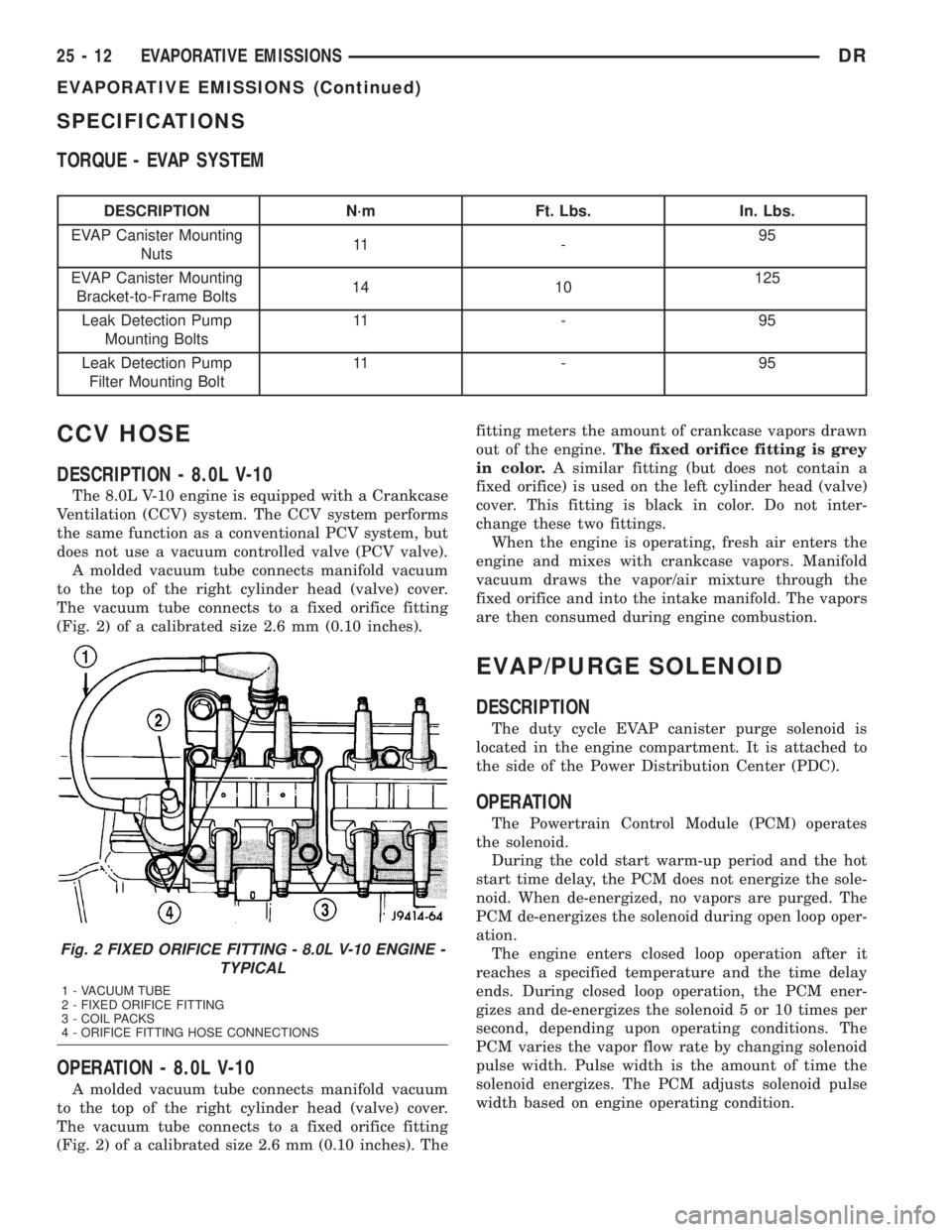
DESCRIPTION - 8.0L V-10
The 8.0L V-10 engine is equipped with a Crankcase
Ventilation (CCV) system. The CCV system performs
the same function as a conventional PCV system, but
does not use a vacuum controlled valve (PCV valve).
A molded vacuum tube connects manifold vacuum
to the top of the right cylinder head (valve) cover.
The vacuum tube connects to a fixed orifice fitting
(Fig. 2) of a calibrated size 2.6 mm (0.10 inches).
OPERATION - 8.0L V-10
A molded vacuum tube connects manifold vacuum
to the top of the right cylinder head (valve) cover.
The vacuum tube connects to a fixed orifice fitting
(Fig. 2) of a calibrated size 2.6 mm (0.10 inches). Thefitting meters the amount of crankcase vapors drawn
out of the engine.The fixed orifice fitting is grey
in color.A similar fitting (but does not contain a
fixed orifice) is used on the left cylinder head (valve)
cover. This fitting is black in color. Do not inter-
change these two fittings.
When the engine is operating, fresh air enters the
engine and mixes with crankcase vapors. Manifold
vacuum draws the vapor/air mixture through the
fixed orifice and into the intake manifold. The vapors
are then consumed during engine combustion.
EVAP/PURGE SOLENOID
DESCRIPTION
The duty cycle EVAP canister purge solenoid is
located in the engine compartment. It is attached to
the side of the Power Distribution Center (PDC).
OPERATION
The Powertrain Control Module (PCM) operates
the solenoid.
During the cold start warm-up period and the hot
start time delay, the PCM does not energize the sole-
noid. When de-energized, no vapors are purged. The
PCM de-energizes the solenoid during open loop oper-
ation.
The engine enters closed loop operation after it
reaches a specified temperature and the time delay
ends. During closed loop operation, the PCM ener-
gizes and de-energizes the solenoid 5 or 10 times per
second, depending upon operating conditions. The
PCM varies the vapor flow rate by changing solenoid
pulse width. Pulse width is the amount of time the
solenoid energizes. The PCM adjusts solenoid pulse
width based on engine operating condition.
Fig. 2 FIXED ORIFICE FITTING - 8.0L V-10 ENGINE -
TYPICAL
1 - VACUUM TUBE
2 - FIXED ORIFICE FITTING
3 - COIL PACKS
4 - ORIFICE FITTING HOSE CONNECTIONS
25 - 12 EVAPORATIVE EMISSIONSDR
EVAPORATIVE EMISSIONS (Continued)
Page 2846 of 2895
5.7L V-8
The 5.7L V-8 engine is equipped with a closed
crankcase ventilation system and a Positive Crank-
case Ventilation (PCV) valve.
This system consists of:
²a PCV valve mounted into the top of the intake
manifold, located to the right / rear of the throttle
body (Fig. 12). The PCV valve is sealed to the intake
manifold with 2 o-rings (Fig. 13).
²passages in the intake manifold.
²tubes and hoses to connect the system compo-
nents.
5.9L V-8
The 5.9L V-8 engine is equipped with a closed
crankcase ventilation system and a positive crank-
case ventilation (PCV) valve.
This system consists of a PCV valve mounted on
the cylinder head (valve) cover with a hose extending
from the valve to the intake manifold (Fig. 14).
Another hose connects the opposite cylinder head
(valve) cover to the air cleaner housing to provide a
source of clean air for the system. A separate crank-
case breather/filter is not used.
OPERATION
The PCV system operates by engine intake mani-
fold vacuum (Fig. 15). Filtered air is routed into the
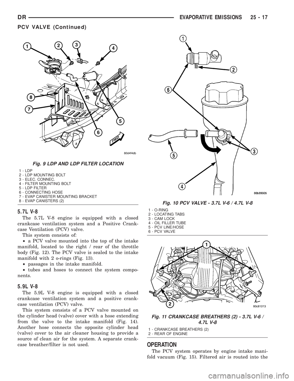
Fig. 9 LDP AND LDP FILTER LOCATION
1 - LDP
2 - LDP MOUNTING BOLT
3 - ELEC. CONNEC.
4 - FILTER MOUNTING BOLT
5 - LDP FILTER
6 - CONNECTING HOSE
7 - EVAP CANISTER MOUNTING BRACKET
8 - EVAP CANISTERS (2)
Fig. 10 PCV VALVE - 3.7L V-6 / 4.7L V-8
1 - O-RING
2 - LOCATING TABS
3 - CAM LOCK
4 - OIL FILLER TUBE
5 - PCV LINE/HOSE
6 - P C V VA LV E
Fig. 11 CRANKCASE BREATHERS (2) - 3.7L V-6 /
4.7L V-8
1 - CRANKCASE BREATHERS (2)
2 - REAR OF ENGINE
DREVAPORATIVE EMISSIONS 25 - 17
PCV VALVE (Continued)
Page 2847 of 2895
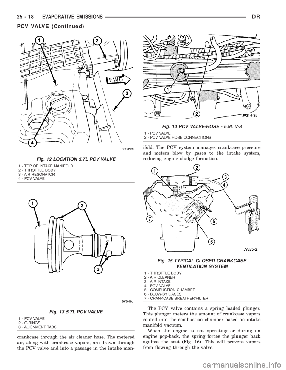
crankcase through the air cleaner hose. The metered
air, along with crankcase vapors, are drawn through
the PCV valve and into a passage in the intake man-ifold. The PCV system manages crankcase pressure
and meters blow by gases to the intake system,
reducing engine sludge formation.
The PCV valve contains a spring loaded plunger.
This plunger meters the amount of crankcase vapors
routed into the combustion chamber based on intake
manifold vacuum.
When the engine is not operating or during an
engine pop-back, the spring forces the plunger back
against the seat (Fig. 16). This will prevent vapors
from flowing through the valve.
Fig. 12 LOCATION 5.7L PCV VALVE
1 - TOP OF INTAKE MANIFOLD
2 - THROTTLE BODY
3 - AIR RESONATOR
4 - P C V VA LV E
Fig. 13 5.7L PCV VALVE
1 - P C V VA LV E
2 - O-RINGS
3 - ALIGNMENT TABS
Fig. 14 PCV VALVE/HOSE - 5.9L V-8
1 - P C V VA LV E
2 - PCV VALVE HOSE CONNECTIONS
Fig. 15 TYPICAL CLOSED CRANKCASE
VENTILATION SYSTEM
1 - THROTTLE BODY
2 - AIR CLEANER
3 - AIR INTAKE
4 - P C V VA LV E
5 - COMBUSTION CHAMBER
6 - BLOW-BY GASES
7 - CRANKCASE BREATHER/FILTER
25 - 18 EVAPORATIVE EMISSIONSDR
PCV VALVE (Continued)
Page 2848 of 2895
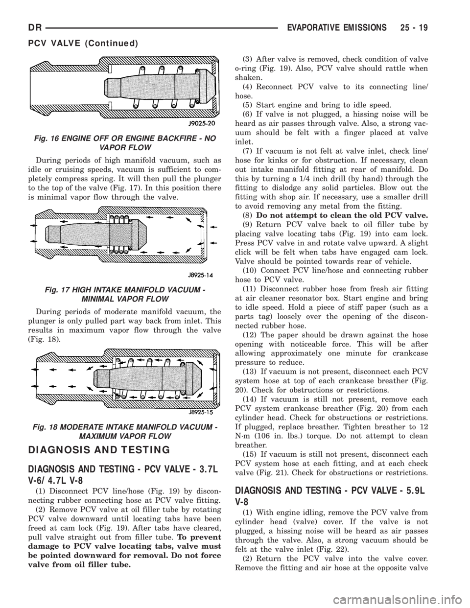
During periods of high manifold vacuum, such as
idle or cruising speeds, vacuum is sufficient to com-
pletely compress spring. It will then pull the plunger
to the top of the valve (Fig. 17). In this position there
is minimal vapor flow through the valve.
During periods of moderate manifold vacuum, the
plunger is only pulled part way back from inlet. This
results in maximum vapor flow through the valve
(Fig. 18).
DIAGNOSIS AND TESTING
DIAGNOSIS AND TESTING - PCV VALVE - 3.7L
V-6/ 4.7L V-8
(1) Disconnect PCV line/hose (Fig. 19) by discon-
necting rubber connecting hose at PCV valve fitting.
(2) Remove PCV valve at oil filler tube by rotating
PCV valve downward until locating tabs have been
freed at cam lock (Fig. 19). After tabs have cleared,
pull valve straight out from filler tube.To prevent
damage to PCV valve locating tabs, valve must
be pointed downward for removal. Do not force
valve from oil filler tube.(3) After valve is removed, check condition of valve
o-ring (Fig. 19). Also, PCV valve should rattle when
shaken.
(4) Reconnect PCV valve to its connecting line/
hose.
(5) Start engine and bring to idle speed.
(6) If valve is not plugged, a hissing noise will be
heard as air passes through valve. Also, a strong vac-
uum should be felt with a finger placed at valve
inlet.
(7) If vacuum is not felt at valve inlet, check line/
hose for kinks or for obstruction. If necessary, clean
out intake manifold fitting at rear of manifold. Do
this by turning a 1/4 inch drill (by hand) through the
fitting to dislodge any solid particles. Blow out the
fitting with shop air. If necessary, use a smaller drill
to avoid removing any metal from the fitting.
(8)Do not attempt to clean the old PCV valve.
(9) Return PCV valve back to oil filler tube by
placing valve locating tabs (Fig. 19) into cam lock.
Press PCV valve in and rotate valve upward. A slight
click will be felt when tabs have engaged cam lock.
Valve should be pointed towards rear of vehicle.
(10) Connect PCV line/hose and connecting rubber
hose to PCV valve.
(11) Disconnect rubber hose from fresh air fitting
at air cleaner resonator box. Start engine and bring
to idle speed. Hold a piece of stiff paper (such as a
parts tag) loosely over the opening of the discon-
nected rubber hose.
(12) The paper should be drawn against the hose
opening with noticeable force. This will be after
allowing approximately one minute for crankcase
pressure to reduce.
(13) If vacuum is not present, disconnect each PCV
system hose at top of each crankcase breather (Fig.
20). Check for obstructions or restrictions.
(14) If vacuum is still not present, remove each
PCV system crankcase breather (Fig. 20) from each
cylinder head. Check for obstructions or restrictions.
If plugged, replace breather. Tighten breather to 12
N´m (106 in. lbs.) torque. Do not attempt to clean
breather.
(15) If vacuum is still not present, disconnect each
PCV system hose at each fitting, and at each check
valve (Fig. 21). Check for obstructions or restrictions.DIAGNOSIS AND TESTING - PCV VALVE - 5.9L
V-8
(1) With engine idling, remove the PCV valve from
cylinder head (valve) cover. If the valve is not
plugged, a hissing noise will be heard as air passes
through the valve. Also, a strong vacuum should be
felt at the valve inlet (Fig. 22).
(2) Return the PCV valve into the valve cover.
Remove the fitting and air hose at the opposite valve
Fig. 16 ENGINE OFF OR ENGINE BACKFIRE - NO
VAPOR FLOW
Fig. 17 HIGH INTAKE MANIFOLD VACUUM -
MINIMAL VAPOR FLOW
Fig. 18 MODERATE INTAKE MANIFOLD VACUUM -
MAXIMUM VAPOR FLOW
DREVAPORATIVE EMISSIONS 25 - 19
PCV VALVE (Continued)
Page 2851 of 2895
tabs, valve must be pointed downward for
removal. Do not force valve from oil filler tube.
(3) After valve is removed, check condition of valve
o-ring (Fig. 25).
5.7L V-8
The PCV valve is mounted into the top of the
intake manifold, located to the right / rear of the
throttle body (Fig. 12). The PCV valve is sealed to
the intake manifold with 2 o-rings (Fig. 13).
(1) Remove PCV valve by rotating counter-clock-
wise 90 degrees until locating tabs have been freed.
After tabs have cleared, pull valve straight up from
intake manifold.
(2) After valve is removed, check condition of 2
valve o-rings.
INSTALLATION
3.7L V6 / 4.7L V-8
The PCV valve is located on the oil filler tube. Two
locating tabs are located on the side of the valve.
These 2 tabs fit into a cam lock in the oil filler tube.
An o-ring seals the valve to the filler tube.
(1) Return PCV valve back to oil filler tube by
placing valve locating tabs into cam lock. Press PCV
valve in and rotate valve upward. A slight click will
be felt when tabs have engaged cam lock. Valve
should be pointed towards rear of vehicle.
(2) Connect PCV line/hose and rubber hose to PCV
valve.
5.7L V-8
(1) Clean out intake manifold opening.
(2) Check condition of 2 o-rings on PCV valve.
(3) Apply engine oil to 2 o-rings.
(4) Place PCV valve into intake manifold and
rotate 90 degrees clockwise for installation.
VACUUM LINES
DESCRIPTION
A vacuum schematic for emission related items can
be found on the vehicles VECI label. Refer to Vehicle
Emission Control Information (VECI) Label for label
location.
VAPOR CANISTER
DESCRIPTION
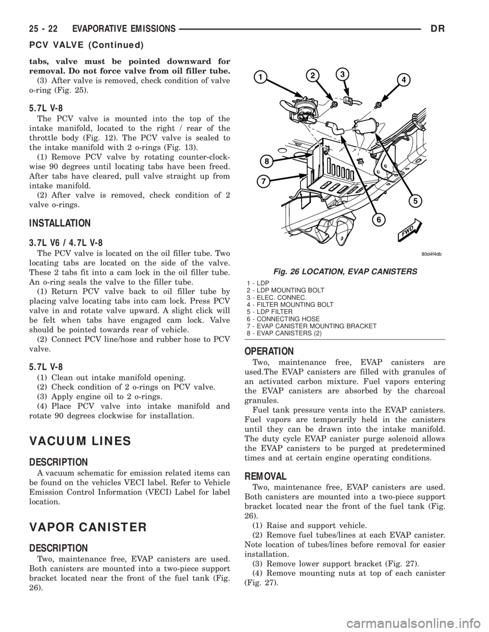
Two, maintenance free, EVAP canisters are used.
Both canisters are mounted into a two-piece support
bracket located near the front of the fuel tank (Fig.
26).
OPERATION
Two, maintenance free, EVAP canisters are
used.The EVAP canisters are filled with granules of
an activated carbon mixture. Fuel vapors entering
the EVAP canisters are absorbed by the charcoal
granules.
Fuel tank pressure vents into the EVAP canisters.
Fuel vapors are temporarily held in the canisters
until they can be drawn into the intake manifold.
The duty cycle EVAP canister purge solenoid allows
the EVAP canisters to be purged at predetermined
times and at certain engine operating conditions.
REMOVAL
Two, maintenance free, EVAP canisters are used.
Both canisters are mounted into a two-piece support
bracket located near the front of the fuel tank (Fig.
26).
(1) Raise and support vehicle.
(2) Remove fuel tubes/lines at each EVAP canister.
Note location of tubes/lines before removal for easier
installation.
(3) Remove lower support bracket (Fig. 27).
(4) Remove mounting nuts at top of each canister
(Fig. 27).
Fig. 26 LOCATION, EVAP CANISTERS
1 - LDP
2 - LDP MOUNTING BOLT
3 - ELEC. CONNEC.
4 - FILTER MOUNTING BOLT
5 - LDP FILTER
6 - CONNECTING HOSE
7 - EVAP CANISTER MOUNTING BRACKET
8 - EVAP CANISTERS (2)
25 - 22 EVAPORATIVE EMISSIONSDR
PCV VALVE (Continued)
Page 2873 of 2895
INDICATOR - DESCRIPTION, UPSHIFT....8J-40
INDICATOR - DESCRIPTION, WAIT-TO-
START .............................8J-42
INDICATOR - DESCRIPTION, WASHER
FLUID..............................8J-42
INDICATOR - DESCRIPTION, WATER-IN-
FUEL..............................8J-43
INDICATOR - DIAGNOSIS AND TESTING,
BRAKE.............................8J-19
INDICATOR - OPERATION, ABS..........8J-17
INDICATOR - OPERATION, AIRBAG.......8J-18
INDICATOR - OPERATION, BRAKE/PARK
BRAKE.............................8J-19
INDICATOR - OPERATION, CARGO LAMP . . 8J-20
INDICATOR - OPERATION, CHECK
GAUGES............................8J-21
INDICATOR - OPERATION, CRUISE.......8J-22
INDICATOR - OPERATION, DOOR AJAR . . . 8J-23
INDICATOR - OPERATION, ETC..........8J-25
INDICATOR - OPERATION, GEAR
SELECTOR..........................8J-27
INDICATOR - OPERATION, HIGH BEAM....8J-28
INDICATOR - OPERATION, LAMP OUT....8J-28
INDICATOR - OPERATION, LOW FUEL.....8J-29
INDICATOR - OPERATION, OVERDRIVE
OFF ...............................8J-33
INDICATOR - OPERATION, SEATBELT.....8J-34
INDICATOR - OPERATION, SECURITY.....8J-35
INDICATOR - OPERATION, SERVICE 4WD . . 8J-36
INDICATOR - OPERATION, TRANS TEMP . . 8J-38
INDICATOR - OPERATION, TURN SIGNAL . . 8J-39
INDICATOR - OPERATION, UPSHIFT......8J-40
INDICATOR - OPERATION, WAIT-TO-
START .............................8J-42
INDICATOR - OPERATION, WASHER
FLUID..............................8J-42
INDICATOR - OPERATION, WATER-IN-
FUEL..............................8J-43
INDICATOR LAMP - DESCRIPTION,
SENTRY KEY IMMOBILIZER SYSTEM......8Q-5
INDICATOR LAMP - OPERATION,
SENTRY KEY IMMOBILIZER SYSTEM......8Q-5
INDICATOR LAMP (MIL) - DESCRIPTION,
MALFUNCTION.......................8J-30
INDICATOR LAMP (MIL) - OPERATION,
MALFUNCTION.......................8J-30
INDICATOR TEST - STANDARD
PROCEDURE, BUILT-IN................8F-10
INDICATORS - DIAGNOSIS AND
TESTING, TREAD WEAR................22-7
INERTIA HINGE COVER - INSTALLATION,
CENTER SEAT BACK..................23-78
INERTIA HINGE COVER - REMOVAL,
CENTER SEAT BACK..................23-78
INFLATION PRESSURES - DESCRIPTION,
TIRE................................22-6
INFO CENTER - DESCRIPTION,
ELECTRONIC VEHICLE.................8M-7
INFO CENTER - INSTALLATION,
ELECTRONIC VEHICLE................8M-10
INFO CENTER - OPERATION,
ELECTRONIC VEHICLE.................8M-8
INFO CENTER - REMOVAL, ELECTRONIC
VEHICLE...........................8M-10
INITIAL OPERATION - STANDARD
PROCEDURE, POWER STEERING
PUMP.............................19-39
INITIALIZATION, STANDARD PROCEDURE
- SENTRY KEY IMMOBILIZER SYSTEM....8Q-3
INJECTION PUMP - DESCRIPTION, FUEL . . 14-64
INJECTION PUMP - INSTALLATION, FUEL . 14-67
INJECTION PUMP - OPERATION, FUEL
....14-64
INJECTION PUMP - REMOVAL, FUEL
.....14-65
INJECTION PUMP TIMING - DIAGNOSIS
AND TESTING, FUEL
..................14-65
INJECTOR - DESCRIPTION, FUEL
. . . 14-32,14-85
INJECTOR - INSTALLATION, FUEL
........14-87
INJECTOR - OPERATION, FUEL
.....14-32,14-86
INJECTOR - REMOVAL, FUEL
...........14-87
INJECTOR FIRING ORDER, DIESEL -
FUEL
..............................14-60
INJECTOR RAIL - DESCRIPTION, FUEL
....14-89
INJECTOR RAIL - INSTALLATION, FUEL
. . . 14-90
INJECTOR RAIL - OPERATION, FUEL
.....14-89
INJECTOR RAIL - REMOVAL, FUEL
.......14-89
INLET AIR TEMPERATURE SENSOR/
PRESSURE SENSOR - DESCRIPTION
.....14-90INLET AIR TEMPERATURE SENSOR/
PRESSURE SENSOR - INSTALLATION.....14-90
INLET AIR TEMPERATURE SENSOR/
PRESSURE SENSOR - OPERATION.......14-90
INLET AIR TEMPERATURE SENSOR/
PRESSURE SENSOR - REMOVAL........14-90
INLET FILTER - INSTALLATION..........14-23
INLET FILTER - REMOVAL..............14-23
INNER BELT MOLDING - INSTALLATION,
FRONT DOOR.......................23-93
INNER BELT MOLDING - INSTALLATION,
REAR DOOR........................23-94
INNER BELT MOLDING - REMOVAL,
FRONT DOOR.......................23-93
INNER BELT MOLDING - REMOVAL,
REAR DOOR........................23-94
INPUT - OPERATION, ASD SENSE - PCM . . . 8I-6
INPUT CLUTCH ASSEMBLY - ASSEMBLY . 21-552
INPUT CLUTCH ASSEMBLY -
DESCRIPTION......................21-549
INPUT CLUTCH ASSEMBLY -
DISASSEMBLY......................21-550
INPUT CLUTCH ASSEMBLY - OPERATION . 21-549
INPUT SHAFT SEAL - INSTALLATION,
STEERING GEAR.....................19-28
INPUT SHAFT SEAL - REMOVAL,
STEERING GEAR.....................19-25
INPUT SPEED SENSOR - DESCRIPTION . . 21-558
INPUT SPEED SENSOR - INSTALLATION . 21-559
INPUT SPEED SENSOR - OPERATION....21-558
INPUT SPEED SENSOR - REMOVAL.......21-559
INSERTS - INSTALLATION, SPRING TIP....2-42
INSERTS - REMOVAL, SPRING TIP........2-41
INSIDE HANDLE ACTUATOR -
INSTALLATION..................23-22,23-32
INSIDE HANDLE ACTUATOR - REMOVAL . . 23-22,
23-31
INSTALLED - INSTALLATION, FRONT OIL
SEAL - FRONT COVER.................9-384
INSTALLED - REMOVAL, FRONT OIL
SEAL - FRONT COVER.................9-384
INSTRUMENT CLUSTER - ASSEMBLY.....8J-15
INSTRUMENT CLUSTER - DESCRIPTION . . . 8J-2
INSTRUMENT CLUSTER - DIAGNOSIS
AND TESTING.......................8J-10
INSTRUMENT CLUSTER - DISASSEMBLY . . 8J-14
INSTRUMENT CLUSTER - INSTALLATION . . 8J-16
INSTRUMENT CLUSTER - OPERATION.....8J-6
INSTRUMENT CLUSTER - REMOVAL.....8J-14
INSTRUMENT PANEL ANTENNA CABLE -
INSTALLATION.......................8A-7
INSTRUMENT PANEL ANTENNA CABLE -
REMOVAL...........................8A-6
INSTRUMENT PANEL ASSEMBLY -
INSTALLATION.......................23-56
INSTRUMENT PANEL ASSEMBLY -
REMOVAL..........................23-53
INSTRUMENT PANEL CENTER BEZEL -
INSTALLATION.......................23-58
INSTRUMENT PANEL CENTER BEZEL -
REMOVAL..........................23-58
INSTRUMENT PANEL DRIVER SIDE
BEZEL - INSTALLATION................23-59
INSTRUMENT PANEL DRIVER SIDE
BEZEL - REMOVAL...................23-58
INSTRUMENT PANEL DUCTS -
INSTALLATION.......................24-29
INSTRUMENT PANEL DUCTS - REMOVAL . 24-29
INSTRUMENT PANEL HEADLAMP
SWITCH BEZEL - INSTALLATION.........23-57
INSTRUMENT PANEL HEADLAMP
SWITCH BEZEL - REMOVAL............23-57
INSTRUMENT PANEL LOWER
SURROUND - INSTALLATION...........23-60
INSTRUMENT PANEL LOWER
SURROUND - REMOVAL...............23-60
INSTRUMENT PANEL TOP COVER -
INSTALLATION.......................23-60
INSTRUMENT PANEL TOP COVER -
REMOVAL..........................23-59
INTAKE AIR HEATER - DESCRIPTION.....14-91
INTAKE AIR HEATER - INSTALLATION
.....14-91
INTAKE AIR HEATER - OPERATION
.......14-91
INTAKE AIR HEATER - REMOVAL
........14-91
INTAKE AIR HEATER RELAY -
DESCRIPTION
.......................14-92
INTAKE AIR HEATER RELAY -
INSTALLATION
.......................14-93INTAKE AIR HEATER RELAY -
OPERATION.........................14-92
INTAKE AIR HEATER RELAY - REMOVAL . . 14-93
INTAKE AIR TEMPERATURE SENSOR -
DESCRIPTION.......................14-36
INTAKE AIR TEMPERATURE SENSOR -
INSTALLATION.......................14-38
INTAKE AIR TEMPERATURE SENSOR -
OPERATION.........................14-36
INTAKE AIR TEMPERATURE SENSOR -
REMOVAL..........................14-36
INTAKE AIR TEMPERATURE SENSOR/
MAP SENSOR - DESCRIPTION..........14-93
INTAKE AIR TEMPERATURE SENSOR/
MAP SENSOR - INSTALLATION..........14-94
INTAKE AIR TEMPERATURE SENSOR/
MAP SENSOR - OPERATION............14-93
INTAKE AIR TEMPERATURE SENSOR/
MAP SENSOR - REMOVAL.............14-93
INTAKE MANIFOLD - CLEANING....9-158,9-219,
9-275,9-346,9-402
INTAKE MANIFOLD - DESCRIPTION . 9-157,9-219,
9-274,9-401,9-71
INTAKE MANIFOLD - INSPECTION . . 9-158,9-219,
9-275,9-346,9-402
INTAKE MANIFOLD - INSTALLATION.....9-158,
9-219,9-275,9-346,9-402,9-72
INTAKE MANIFOLD - OPERATION........9-274
INTAKE MANIFOLD - REMOVAL....9-157,9-219,
9-275,9-345,9-401,9-72
INTAKE MANIFOLD LEAKAGE -
DIAGNOSIS AND TESTING . . . 9-157,9-219,9-274,
9-401
INTAKE MANIFOLD LEAKS - DIAGNOSIS
AND TESTING........................9-71
INTAKE SYSTEM - INSTALLATION, AIR....9-194
INTAKE SYSTEM - REMOVAL, AIR.......9-194
INTAKE/EXHAUST VALVES & SEATS -
CLEANING..........................9-248
INTAKE/EXHAUST VALVES & SEATS -
DESCRIPTION....9-122,9-246,9-27,9-305,9-375
INTAKE/EXHAUST VALVES & SEATS -
INSPECTION........................9-248
INTAKE/EXHAUST VALVES & SEATS -
INSTALLATION..............9-123,9-248,9-29
INTAKE/EXHAUST VALVES & SEATS -
REMOVAL.................9-122,9-248,9-28
INTEGRATED POWER MODULE -
DESCRIPTION.....................8W-97-3
INTEGRATED POWER MODULE -
INSTALLATION....................8W-97-4
INTEGRATED POWER MODULE -
OPERATION.......................8W-97-3
INTEGRATED POWER MODULE -
REMOVAL........................8W-97-3
INTERIOR - CAUTION.................23-63
INTERLOCK - ADJUSTMENTS, BRAKE
TRANSMISSION SHIFT . . . 21-195,21-376,21-540
INTERLOCK - DIAGNOSIS AND TESTING,
BRAKE TRANSMISSION SHIFT . . . 21-195,21-375,
21-540
INTERLOCK SYSTEM - DESCRIPTION,
BRAKE TRANSMISSION SHIFT . . . 21-194,21-375,
21-540
INTERLOCK SYSTEM - OPERATION,
BRAKE TRANSMISSION SHIFT . . . 21-194,21-375,
21-540
INTERNATIONAL SYMBOLS -
DESCRIPTION......................Intro.-6
INTERNATIONAL SYMBOLS -
DESCRIPTION.........................0-1
INTRODUCTION - DIAGNOSIS AND
TESTING, ENGINE DIAGNOSIS.....9-178,9-225,
9-353,9-4,9-93
INVERTED FLARING - STANDARD
PROCEDURE, DOUBLE..................5-7
IOD FUSE - DESCRIPTION...........8W-97-6
IOD FUSE - INSTALLATION...........8W-97-7
IOD FUSE - OPERATION.............8W-97-6
IOD FUSE - REMOVAL..............8W-97-6
ISO FLARING - STANDARD PROCEDURE....5-7
ISOLATORS - INSTALLATION, BODY
......23-37
ISOLATORS - REMOVAL, BODY
.........23-36
JOINT - DIAGNOSIS AND TESTING,
LOWER BALL
........................2-18
JOINT - DIAGNOSIS AND TESTING,
UPPER BALL
.........................2-26
JOINT - INSTALLATION, LOWER BALL
. 2-19,2-33
18 INDEXDR
Description Group-Page Description Group-Page Description Group-Page