DODGE RAM 2003 Service Repair Manual
Manufacturer: DODGE, Model Year: 2003, Model line: RAM, Model: DODGE RAM 2003Pages: 2895, PDF Size: 83.15 MB
Page 2451 of 2895
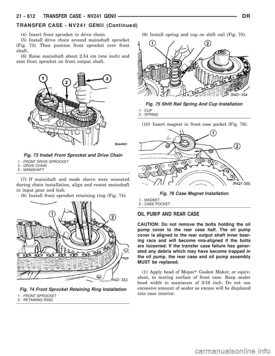
(4) Insert front sprocket in drive chain.
(5) Install drive chain around mainshaft sprocket
(Fig. 73). Then position front sprocket over front
shaft.
(6) Raise mainshaft about 2.54 cm (one inch) and
seat front sprocket on front output shaft.
(7) If mainshaft and mode sleeve were unseated
during chain installation, align and reseat mainshaft
in input gear and hub.
(8) Install front sprocket retaining ring (Fig. 74).(9) Install spring and cup on shift rail (Fig. 75).
(10) Insert magnet in front case pocket (Fig. 76).
OIL PUMP AND REAR CASE
CAUTION: Do not remove the bolts holding the oil
pump cover to the rear case half. The oil pump
cover is aligned to the rear output shaft inner bear-
ing race and will become mis-aligned if the bolts
are loosened. If the transfer case failure has gener-
ated any debris which may have become trapped in
the oil pump. the rear case and oil pump assembly
MUST be replaced.
(1) Apply bead of MopartGasket Maker, or equiv-
alent, to mating surface of front case. Keep sealer
bead width to maximum of 3/16 inch. Do not use
excessive amount of sealer as excess will be displaced
into case interior.
Fig. 73 Install Front Sprocket and Drive Chain
1 - FRONT DRIVE SPROCKET
2 - DRIVE CHAIN
3 - MAINSHAFT
Fig. 74 Front Sprocket Retaining Ring Installation
1 - FRONT SPROCKET
2 - RETAINING RING
Fig. 75 Shift Rail Spring And Cup Installation
1 - CUP
2 - SPRING
Fig. 76 Case Magnet Installation
1 - MAGNET
2 - CASE POCKET
21 - 612 TRANSFER CASE - NV241 GENIIDR
TRANSFER CASE - NV241 GENII (Continued)
Page 2452 of 2895
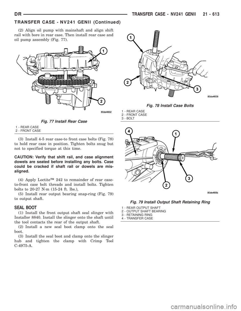
(2) Align oil pump with mainshaft and align shift
rail with bore in rear case. Then install rear case and
oil pump assembly (Fig. 77).
(3) Install 4-5 rear case-to front case bolts (Fig. 78)
to hold rear case in position. Tighten bolts snug but
not to specified torque at this time.
CAUTION: Verify that shift rail, and case alignment
dowels are seated before installing any bolts. Case
could be cracked if shaft rail or dowels are mis-
aligned.
(4) Apply LoctiteŸ 242 to remainder of rear case-
to-front case bolt threads and install bolts. Tighten
bolts to 20-27 N´m (15-24 ft. lbs.),
(5) Install rear output bearing snap-ring (Fig. 79)
to output shaft.
SEAL BOOT
(1) Install the front output shaft seal slinger with
Installer 8840. Install the slinger onto the shaft until
the tool contacts the rear of the output shaft.
(2) Install a new seal boot clamp onto the seal
boot.
(3) Install the seal boot and clamp onto the slinger
hub and tighten the clamp with Crimp Tool
C-4975-A.
Fig. 77 Install Rear Case
1 - REAR CASE
2 - FRONT CASE
Fig. 78 Install Case Bolts
1 - REAR CASE
2 - FRONT CASE
3 - BOLT
Fig. 79 Install Output Shaft Retaining Ring
1 - REAR OUTPUT SHAFT
2 - OUTPUT SHAFT BEARING
3 - RETAINING RING
4 - TRANSFER CASE
DRTRANSFER CASE - NV241 GENII 21 - 613
TRANSFER CASE - NV241 GENII (Continued)
Page 2453 of 2895
REAR EXTENSION
(1) Install new seal in rear extension housing seal
with Installer D-163 and Handle C-4171..
(2) Apply bead of MopartGasket Maker, or equiv-
alent, to mating surface of rear extension housing.
Keep sealer bead width to maximum of 3/16 inch. Do
not use excessive amount of sealer as excess could be
displaced into output bearing.
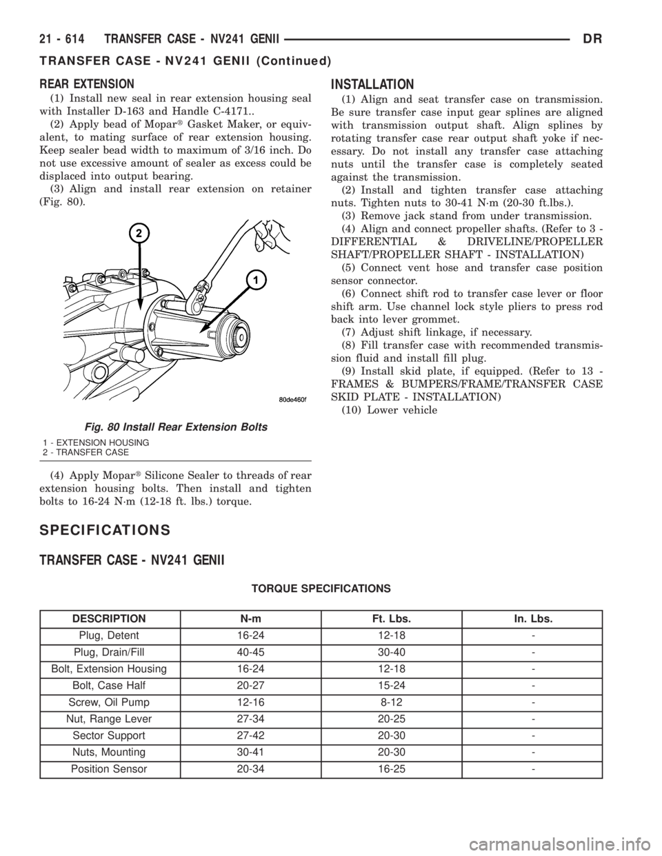
(3) Align and install rear extension on retainer
(Fig. 80).
(4) Apply MopartSilicone Sealer to threads of rear
extension housing bolts. Then install and tighten
bolts to 16-24 N´m (12-18 ft. lbs.) torque.
INSTALLATION
(1) Align and seat transfer case on transmission.
Be sure transfer case input gear splines are aligned
with transmission output shaft. Align splines by
rotating transfer case rear output shaft yoke if nec-
essary. Do not install any transfer case attaching
nuts until the transfer case is completely seated
against the transmission.
(2) Install and tighten transfer case attaching
nuts. Tighten nuts to 30-41 N´m (20-30 ft.lbs.).
(3) Remove jack stand from under transmission.
(4) Align and connect propeller shafts. (Refer to 3 -
DIFFERENTIAL & DRIVELINE/PROPELLER
SHAFT/PROPELLER SHAFT - INSTALLATION)
(5) Connect vent hose and transfer case position
sensor connector.
(6) Connect shift rod to transfer case lever or floor
shift arm. Use channel lock style pliers to press rod
back into lever grommet.
(7) Adjust shift linkage, if necessary.
(8) Fill transfer case with recommended transmis-
sion fluid and install fill plug.
(9) Install skid plate, if equipped. (Refer to 13 -
FRAMES & BUMPERS/FRAME/TRANSFER CASE
SKID PLATE - INSTALLATION)
(10) Lower vehicle
SPECIFICATIONS
TRANSFER CASE - NV241 GENII
TORQUE SPECIFICATIONS
DESCRIPTION N-m Ft. Lbs. In. Lbs.
Plug, Detent 16-24 12-18 -
Plug, Drain/Fill 40-45 30-40 -
Bolt, Extension Housing 16-24 12-18 -
Bolt, Case Half 20-27 15-24 -
Screw, Oil Pump 12-16 8-12 -
Nut, Range Lever 27-34 20-25 -
Sector Support 27-42 20-30 -
Nuts, Mounting 30-41 20-30 -
Position Sensor 20-34 16-25 -
Fig. 80 Install Rear Extension Bolts
1 - EXTENSION HOUSING
2 - TRANSFER CASE
21 - 614 TRANSFER CASE - NV241 GENIIDR
TRANSFER CASE - NV241 GENII (Continued)
Page 2454 of 2895
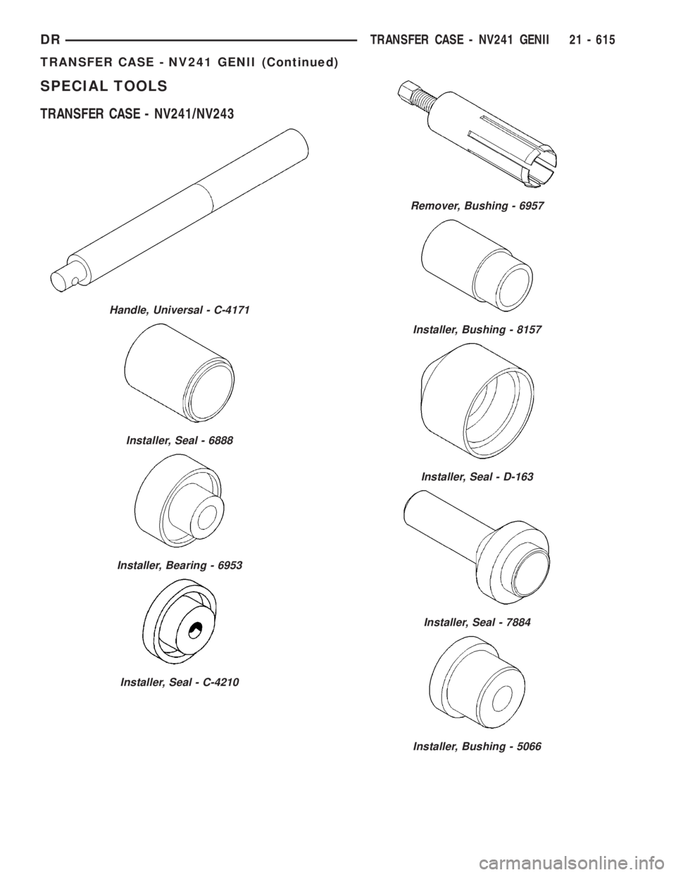
SPECIAL TOOLS
TRANSFER CASE - NV241/NV243
Handle, Universal - C-4171
Installer, Seal - 6888
Installer, Bearing - 6953
Installer, Seal - C-4210
Remover, Bushing - 6957
Installer, Bushing - 8157
Installer, Seal - D-163
Installer, Seal - 7884
Installer, Bushing - 5066
DRTRANSFER CASE - NV241 GENII 21 - 615
TRANSFER CASE - NV241 GENII (Continued)
Page 2455 of 2895
EXTENSION HOUSING
BUSHING AND SEAL
REMOVAL
(1) Raise and support vehicle.
(2) Remove rear propeller shaft. (Refer to 3 - DIF-
FERENTIAL & DRIVELINE/PROPELLER SHAFT/
PROPELLER SHAFT - REMOVAL)
(3) Using a suitable pry tool or slide-hammer
mounted screw, remove the extension housing seal.
(4) Using Remover 8158, remove bushing from
extension housing.
INSTALLATION
(1) Clean fluid residue from sealing surface and
inspect for defects.
(2) Position replacement bushing in extension
housing with fluid port in bushing aligned with slot
in housing.
(3) Using Installer 8157, drive bushing into hous-
ing until installer seats against case.
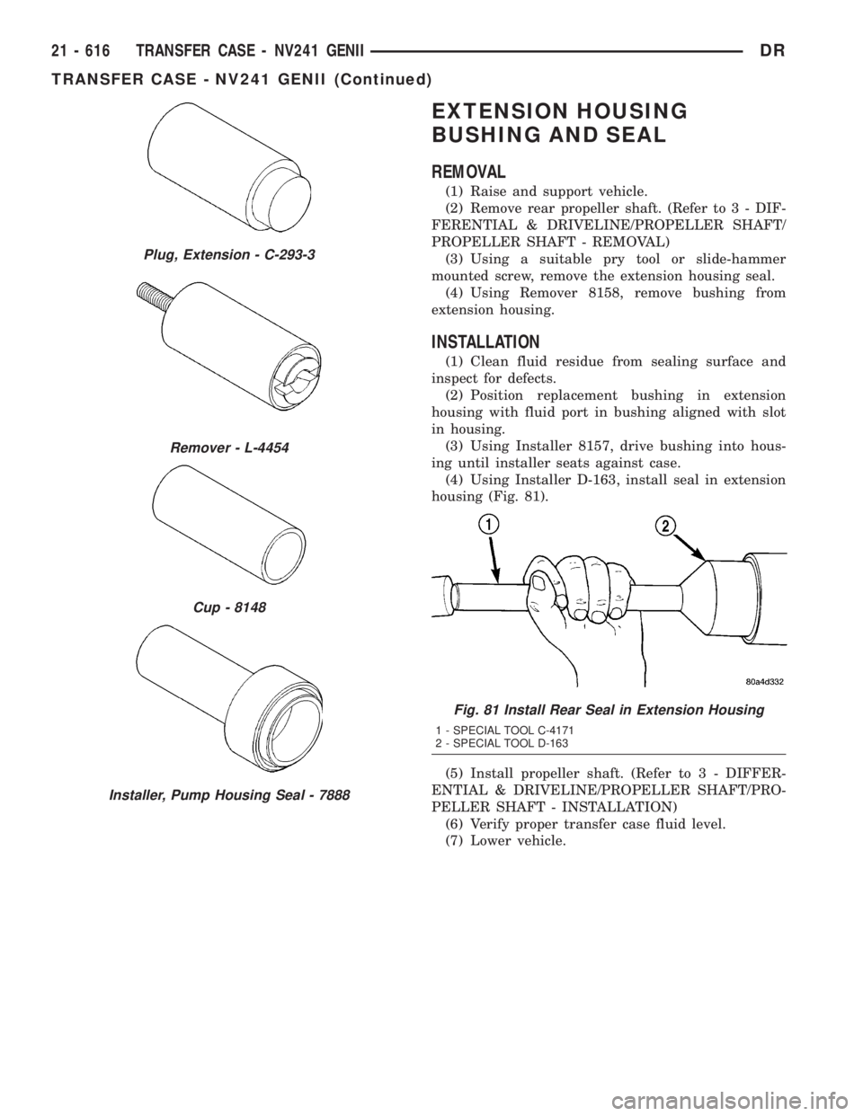
(4) Using Installer D-163, install seal in extension
housing (Fig. 81).
(5) Install propeller shaft. (Refer to 3 - DIFFER-
ENTIAL & DRIVELINE/PROPELLER SHAFT/PRO-
PELLER SHAFT - INSTALLATION)
(6) Verify proper transfer case fluid level.
(7) Lower vehicle.
Plug, Extension - C-293-3
Remover - L-4454
Cup - 8148
Installer, Pump Housing Seal - 7888
Fig. 81 Install Rear Seal in Extension Housing
1 - SPECIAL TOOL C-4171
2 - SPECIAL TOOL D-163
21 - 616 TRANSFER CASE - NV241 GENIIDR
TRANSFER CASE - NV241 GENII (Continued)
Page 2456 of 2895
FLUID
STANDARD PROCEDURE - FLUID DRAIN AND
REFILL
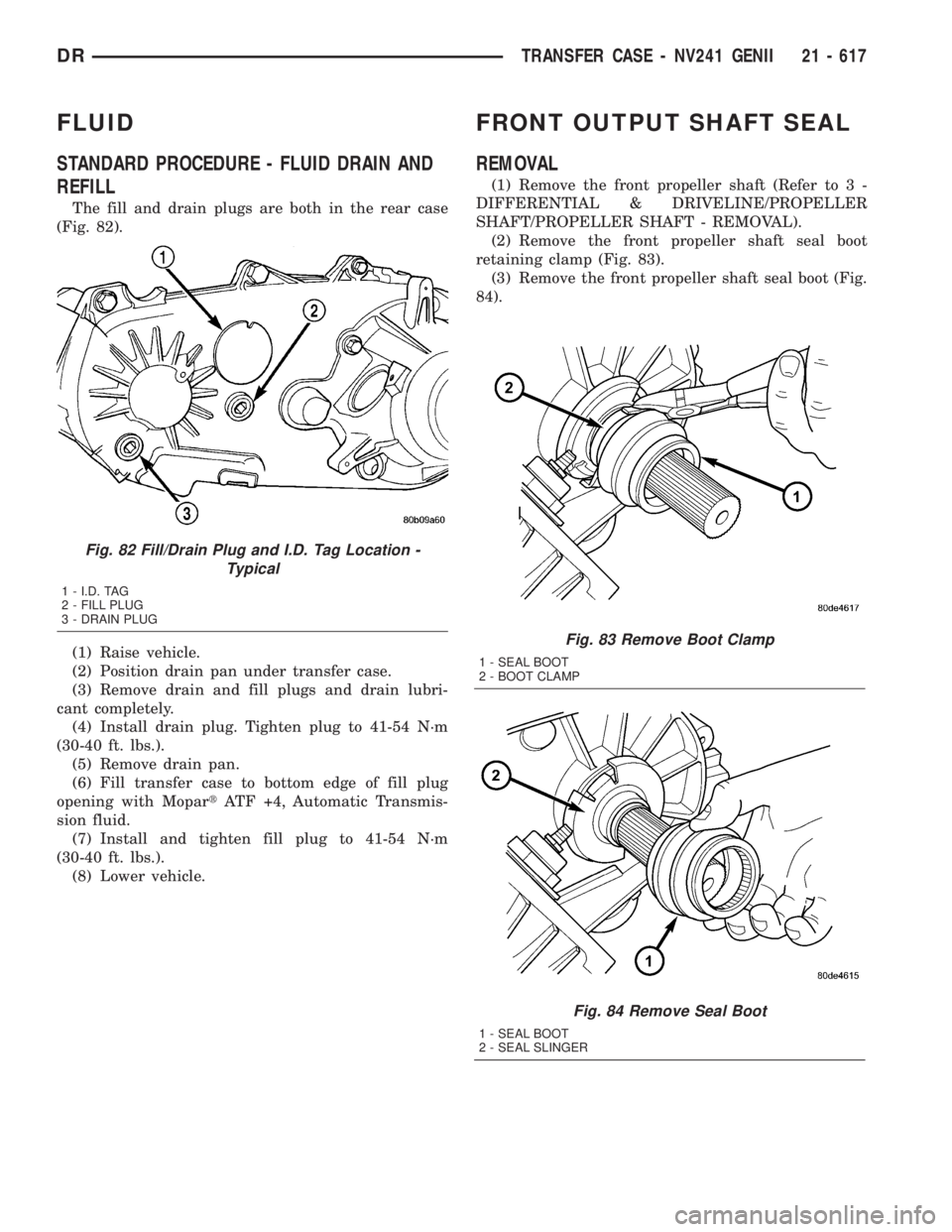
The fill and drain plugs are both in the rear case
(Fig. 82).
(1) Raise vehicle.
(2) Position drain pan under transfer case.
(3) Remove drain and fill plugs and drain lubri-
cant completely.
(4) Install drain plug. Tighten plug to 41-54 N´m
(30-40 ft. lbs.).
(5) Remove drain pan.
(6) Fill transfer case to bottom edge of fill plug
opening with MopartATF +4, Automatic Transmis-
sion fluid.
(7) Install and tighten fill plug to 41-54 N´m
(30-40 ft. lbs.).
(8) Lower vehicle.
FRONT OUTPUT SHAFT SEAL
REMOVAL
(1) Remove the front propeller shaft (Refer to 3 -
DIFFERENTIAL & DRIVELINE/PROPELLER
SHAFT/PROPELLER SHAFT - REMOVAL).
(2) Remove the front propeller shaft seal boot
retaining clamp (Fig. 83).
(3) Remove the front propeller shaft seal boot (Fig.
84).
Fig. 83 Remove Boot Clamp
1 - SEAL BOOT
2 - BOOT CLAMP
Fig. 84 Remove Seal Boot
1 - SEAL BOOT
2 - SEAL SLINGER
Fig. 82 Fill/Drain Plug and I.D. Tag Location -
Typical
1 - I.D. TAG
2 - FILL PLUG
3 - DRAIN PLUG
DRTRANSFER CASE - NV241 GENII 21 - 617
Page 2457 of 2895
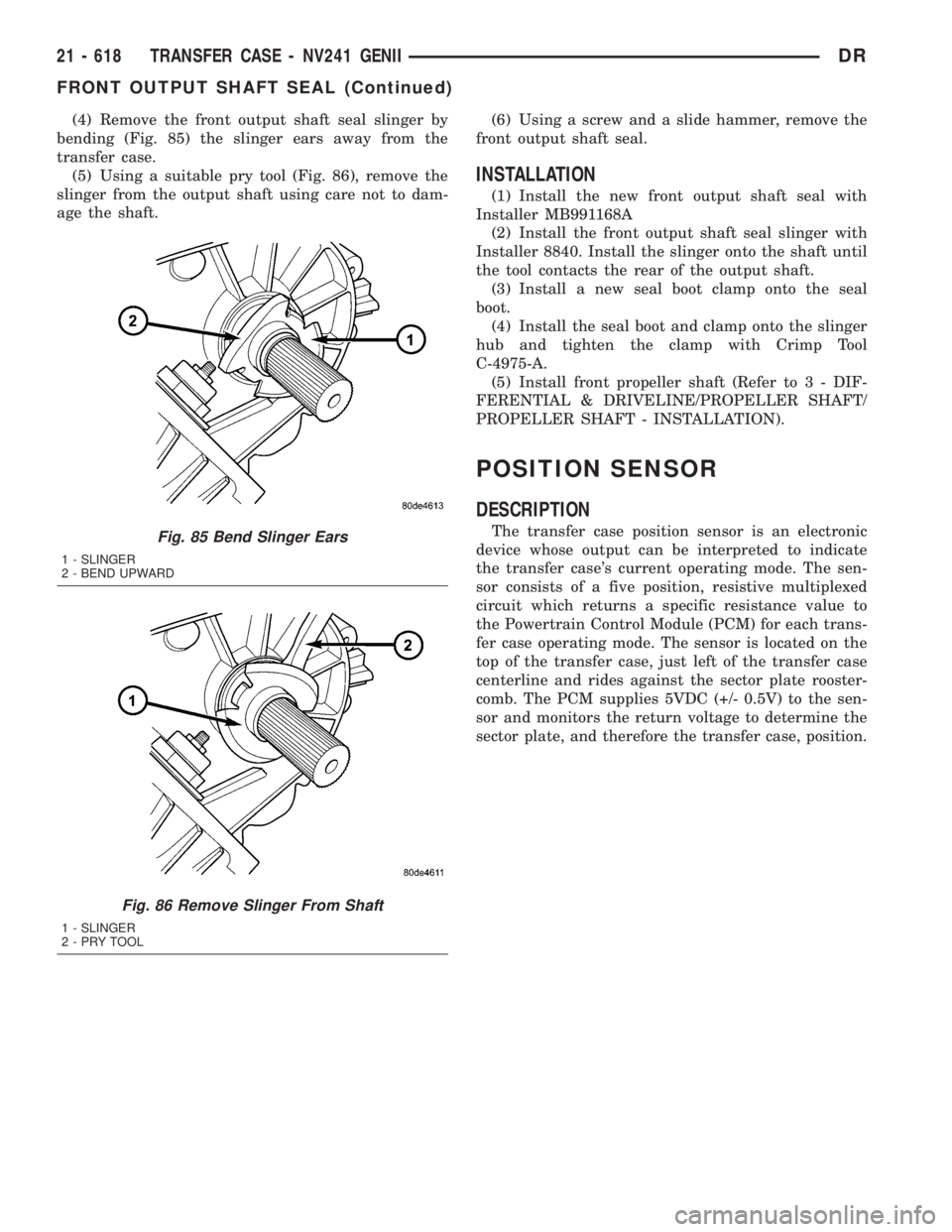
(4) Remove the front output shaft seal slinger by
bending (Fig. 85) the slinger ears away from the
transfer case.
(5) Using a suitable pry tool (Fig. 86), remove the
slinger from the output shaft using care not to dam-
age the shaft.(6) Using a screw and a slide hammer, remove the
front output shaft seal.
INSTALLATION
(1) Install the new front output shaft seal with
Installer MB991168A
(2) Install the front output shaft seal slinger with
Installer 8840. Install the slinger onto the shaft until
the tool contacts the rear of the output shaft.
(3) Install a new seal boot clamp onto the seal
boot.
(4) Install the seal boot and clamp onto the slinger
hub and tighten the clamp with Crimp Tool
C-4975-A.
(5) Install front propeller shaft (Refer to 3 - DIF-
FERENTIAL & DRIVELINE/PROPELLER SHAFT/
PROPELLER SHAFT - INSTALLATION).
POSITION SENSOR
DESCRIPTION
The transfer case position sensor is an electronic
device whose output can be interpreted to indicate
the transfer case's current operating mode. The sen-
sor consists of a five position, resistive multiplexed
circuit which returns a specific resistance value to
the Powertrain Control Module (PCM) for each trans-
fer case operating mode. The sensor is located on the
top of the transfer case, just left of the transfer case
centerline and rides against the sector plate rooster-
comb. The PCM supplies 5VDC (+/- 0.5V) to the sen-
sor and monitors the return voltage to determine the
sector plate, and therefore the transfer case, position.Fig. 85 Bend Slinger Ears
1 - SLINGER
2 - BEND UPWARD
Fig. 86 Remove Slinger From Shaft
1 - SLINGER
2-PRYTOOL
21 - 618 TRANSFER CASE - NV241 GENIIDR
FRONT OUTPUT SHAFT SEAL (Continued)
Page 2458 of 2895
OPERATION
During normal vehicle operation, the Powertrain
Control Module (PCM) monitors the transfer case
position sensor return voltage to determine the oper-ating mode of the transfer case. Refer to the Operat-
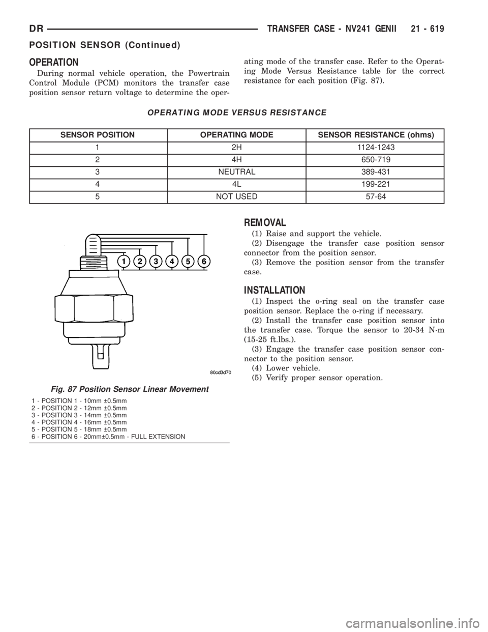
ing Mode Versus Resistance table for the correct
resistance for each position (Fig. 87).
OPERATING MODE VERSUS RESISTANCE
SENSOR POSITION OPERATING MODE SENSOR RESISTANCE (ohms)
1 2H 1124-1243
2 4H 650-719
3 NEUTRAL 389-431
4 4L 199-221
5 NOT USED 57-64
REMOVAL
(1) Raise and support the vehicle.
(2) Disengage the transfer case position sensor
connector from the position sensor.
(3) Remove the position sensor from the transfer
case.
INSTALLATION
(1) Inspect the o-ring seal on the transfer case
position sensor. Replace the o-ring if necessary.
(2) Install the transfer case position sensor into
the transfer case. Torque the sensor to 20-34 N´m
(15-25 ft.lbs.).
(3) Engage the transfer case position sensor con-
nector to the position sensor.
(4) Lower vehicle.
(5) Verify proper sensor operation.
Fig. 87 Position Sensor Linear Movement
1 - POSITION 1 - 10mm 0.5mm
2 - POSITION 2 - 12mm 0.5mm
3 - POSITION 3 - 14mm 0.5mm
4 - POSITION 4 - 16mm 0.5mm
5 - POSITION 5 - 18mm 0.5mm
6 - POSITION 6 - 20mm 0.5mm - FULL EXTENSION
DRTRANSFER CASE - NV241 GENII 21 - 619
POSITION SENSOR (Continued)
Page 2459 of 2895
SHIFT LEVER
REMOVAL
(1) Shift transfer case into 2H.
(2) Raise and support the vehicle.
(3) Loosen adjusting trunnion lock bolt and slide
shift rod out of trunnion. If rod lacks enough travel
to come out of trunnion, push trunnion out of shift
lever.
(4) Lower vehicle.
(5) Remove transfer case shifter knob cap.
(6) Remove nut holding shifter knob to shift lever.
(7) Remove shifter knob.
(8) Remove the shift boot from the shifter console.
(9) Remove the bolts securing the shifter mecha-
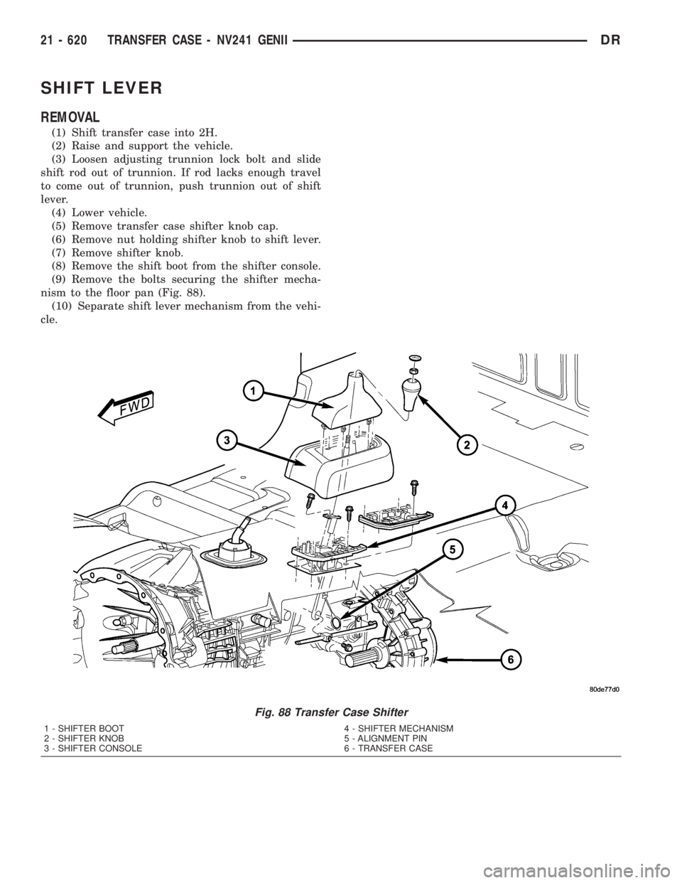
nism to the floor pan (Fig. 88).
(10) Separate shift lever mechanism from the vehi-
cle.
Fig. 88 Transfer Case Shifter
1 - SHIFTER BOOT
2 - SHIFTER KNOB
3 - SHIFTER CONSOLE4 - SHIFTER MECHANISM
5 - ALIGNMENT PIN
6 - TRANSFER CASE
21 - 620 TRANSFER CASE - NV241 GENIIDR
Page 2460 of 2895
INSTALLATION
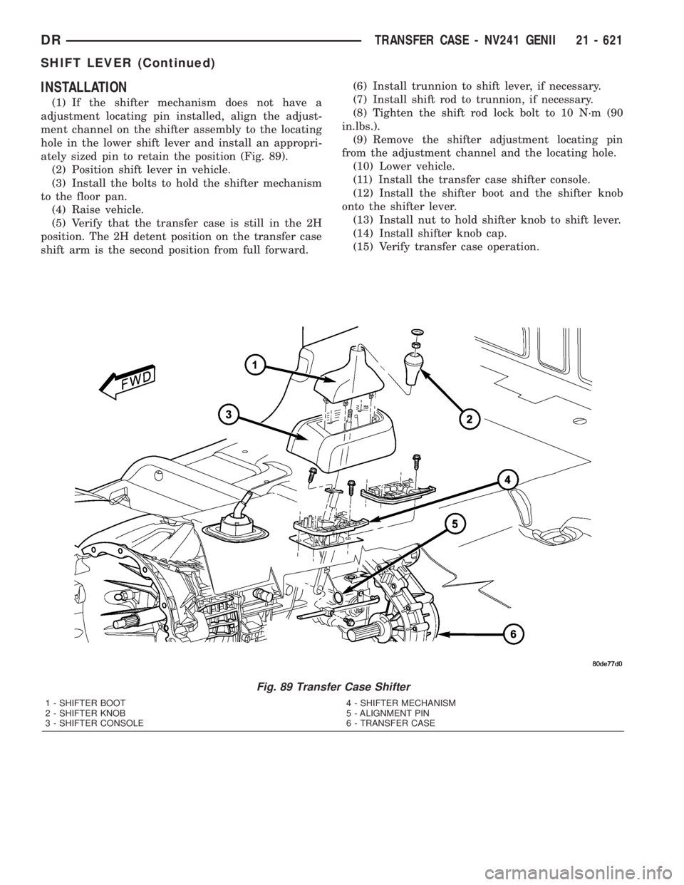
(1) If the shifter mechanism does not have a
adjustment locating pin installed, align the adjust-
ment channel on the shifter assembly to the locating
hole in the lower shift lever and install an appropri-
ately sized pin to retain the position (Fig. 89).
(2) Position shift lever in vehicle.
(3) Install the bolts to hold the shifter mechanism
to the floor pan.
(4) Raise vehicle.
(5) Verify that the transfer case is still in the 2H
position. The 2H detent position on the transfer case
shift arm is the second position from full forward.(6) Install trunnion to shift lever, if necessary.
(7) Install shift rod to trunnion, if necessary.
(8) Tighten the shift rod lock bolt to 10 N´m (90
in.lbs.).
(9) Remove the shifter adjustment locating pin
from the adjustment channel and the locating hole.
(10) Lower vehicle.
(11) Install the transfer case shifter console.
(12) Install the shifter boot and the shifter knob
onto the shifter lever.
(13) Install nut to hold shifter knob to shift lever.
(14) Install shifter knob cap.
(15) Verify transfer case operation.
Fig. 89 Transfer Case Shifter
1 - SHIFTER BOOT
2 - SHIFTER KNOB
3 - SHIFTER CONSOLE4 - SHIFTER MECHANISM
5 - ALIGNMENT PIN
6 - TRANSFER CASE
DRTRANSFER CASE - NV241 GENII 21 - 621
SHIFT LEVER (Continued)