Rear vss DODGE RAM 2003 Service Repair Manual
[x] Cancel search | Manufacturer: DODGE, Model Year: 2003, Model line: RAM, Model: DODGE RAM 2003Pages: 2895, PDF Size: 83.15 MB
Page 393 of 2895

²supplies a reference voltage for the Throttle
Position Sensor (TPS) sensor.
Secondary 5±volt supply:
²supplies the required 5 volt power source to the
oil pressure sensor.
²supplies the required 5 volt power source for the
Vehicle Speed Sensor (VSS) (if equipped).
²supplies the 5 volt power source to the transmis-
sion pressure sensor (certain automatic transmis-
sions).
OPERATION - IGNITION CIRCUIT SENSE
The ignition circuit sense input tells the PCM the
ignition switch has energized the ignition circuit.
Battery voltage is also supplied to the PCM
through the ignition switch when the ignition is in
the RUN or START position. This is referred to as
the9ignition sense9circuit and is used to9wake up9
the PCM. Voltage on the ignition input can be as low
as 6 volts and the PCM will still function. Voltage is
supplied to this circuit to power the PCM's 8-volt reg-
ulator and to allow the PCM to perform fuel, ignition
and emissions control functions.
REMOVAL
USE THE DRB SCAN TOOL TO REPROGRAM
THE NEW POWERTRAIN CONTROL MODULE
(PCM) WITH THE VEHICLES ORIGINAL IDEN-
TIFICATION NUMBER (VIN) AND THE VEHI-
CLES ORIGINAL MILEAGE. IF THIS STEP IS
NOT DONE, A DIAGNOSTIC TROUBLE CODE
(DTC) MAY BE SET.
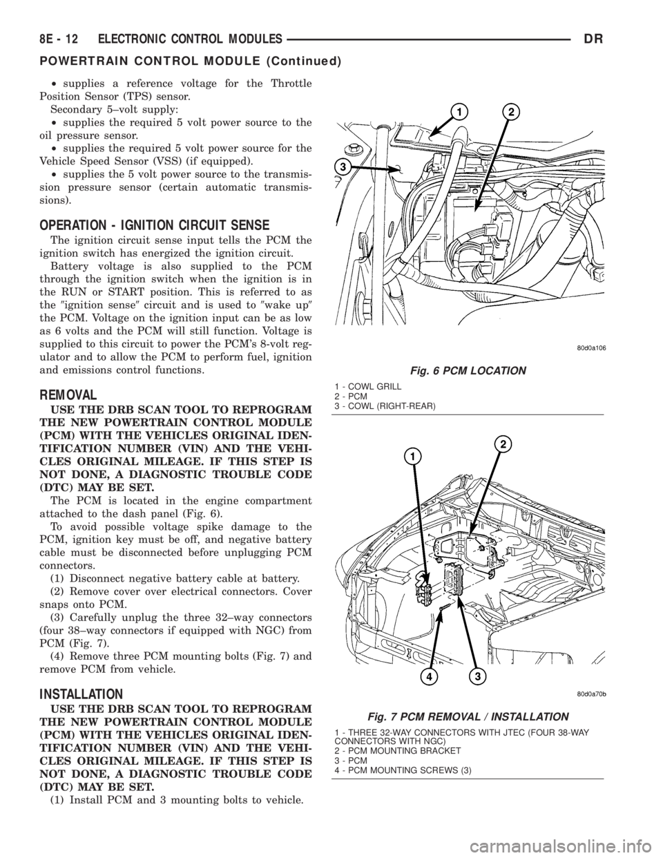
The PCM is located in the engine compartment
attached to the dash panel (Fig. 6).
To avoid possible voltage spike damage to the
PCM, ignition key must be off, and negative battery
cable must be disconnected before unplugging PCM
connectors.
(1) Disconnect negative battery cable at battery.
(2) Remove cover over electrical connectors. Cover
snaps onto PCM.
(3) Carefully unplug the three 32±way connectors
(four 38±way connectors if equipped with NGC) from
PCM (Fig. 7).
(4) Remove three PCM mounting bolts (Fig. 7) and
remove PCM from vehicle.
INSTALLATION
USE THE DRB SCAN TOOL TO REPROGRAM
THE NEW POWERTRAIN CONTROL MODULE
(PCM) WITH THE VEHICLES ORIGINAL IDEN-
TIFICATION NUMBER (VIN) AND THE VEHI-
CLES ORIGINAL MILEAGE. IF THIS STEP IS
NOT DONE, A DIAGNOSTIC TROUBLE CODE
(DTC) MAY BE SET.
(1) Install PCM and 3 mounting bolts to vehicle.
Fig. 6 PCM LOCATION
1 - COWL GRILL
2 - PCM
3 - COWL (RIGHT-REAR)
Fig. 7 PCM REMOVAL / INSTALLATION
1 - THREE 32-WAY CONNECTORS WITH JTEC (FOUR 38-WAY
CONNECTORS WITH NGC)
2 - PCM MOUNTING BRACKET
3 - PCM
4 - PCM MOUNTING SCREWS (3)
8E - 12 ELECTRONIC CONTROL MODULESDR
POWERTRAIN CONTROL MODULE (Continued)
Page 2663 of 2895

WINDSHIELD
WARNING
WINDSHIELD SAFETY PRECAUTIONS
WARNING: DO NOT OPERATE THE VEHICLE
WITHIN 24 HOURS OF WINDSHIELD INSTALLATION.
IT TAKES AT LEAST 24 HOURS FOR URETHANE
ADHESIVE TO CURE. IF IT IS NOT CURED, THE
WINDSHIELD MAY NOT PERFORM PROPERLY IN
AN ACCIDENT.
²URETHANE ADHESIVES ARE APPLIED AS A
SYSTEM. USE GLASS CLEANER, GLASS PREP
SOLVENT, GLASS PRIMER, PVC (VINYL) PRIMER
AND PINCH WELD (FENCE) PRIMER PROVIDED BY
THE ADHESIVE MANUFACTURER. IF NOT, STRUC-
TURAL INTEGRITY COULD BE COMPROMISED.
²DAIMLERCHRYSLER DOES NOT RECOMMEND
GLASS ADHESIVE BY BRAND. TECHNICIANS
SHOULD REVIEW PRODUCT LABELS AND TECHNI-
CAL DATA SHEETS, AND USE ONLY ADHESIVES
THAT THEIR MANUFACTURES WARRANT WILL
RESTORE A VEHICLE TO THE REQUIREMENTS OF
FMVSS 212. TECHNICIANS SHOULD ALSO INSURE
THAT PRIMERS AND CLEANERS ARE COMPATIBLE
WITH THE PARTICULAR ADHESIVE USED.
²BE SURE TO REFER TO THE URETHANE MAN-
UFACTURER'S DIRECTIONS FOR CURING TIME
SPECIFICATIONS, AND DO NOT USE ADHESIVE
AFTER ITS EXPIRATION DATE.
²VAPORS THAT ARE EMITTED FROM THE URE-
THANE ADHESIVE OR PRIMER COULD CAUSE
PERSONAL INJURY. USE THEM IN A WELL-VENTI-
LATED AREA.
²SKIN CONTACT WITH URETHANE ADHESIVE
SHOULD BE AVOIDED. PERSONAL INJURY MAY
RESULT.
²ALWAYS WEAR EYE AND HAND PROTECTION
WHEN WORKING WITH GLASS.
CAUTION: Protect all painted and trimmed surfaces
from coming in contact with urethane or primers.
Be careful not to damage painted surfaces when
removing moldings or cutting urethane around
windshield.
REMOVAL
(1) Remove inside rear view mirror. (Refer to 23 -
BODY/INTERIOR/REAR VIEW MIRROR - REMOV-
AL).
(2) Remove cowl grill. (Refer to 23 - BODY/EXTE-
RIOR/COWL GRILLE - REMOVAL).
(3) Remove the a-pillar weatherstrip retainer.
(Refer to 23 - BODY/WEATHERSTRIP/SEALS/A-
PILLAR WEATHERSTRIP RETAINER - REMOVAL)
(4) Remove the a-pillar trim panels. (Refer to 23 -
BODY/INTERIOR/A-PILLAR TRIM - REMOVAL)
(5) Remove the headliner and from the inside of
the vehicle, cut the upper urethane bonding from
around windshield upper edge using a suitable sharp
cold knife (C-4849). A pneumatic cutting device can
be used but is not recommended. (Refer to 23 -
BODY/INTERIOR/HEADLINER - REMOVAL)
(6) From the outside of the vehicle, cut urethane
bonding from the remaining sides of the windshield
using a suitable sharp cold knife (C-4849). A pneu-
matic cutting device can be used but is not recom-
mended.
(7) Separate windshield from vehicle.
INSTALLATION
WARNING: Allow the urethane at least 24 hours to
cure before returning the vehicle to use.
CAUTION: Roll down the left and right front door
glass and open the rear glass slider (if available)
before installing windshield to avoid pressurizing
the passenger compartment if a door is slammed
before urethane is cured. Water leaks can result.
The windshield fence should be cleaned of most of
its old urethane bonding material. A small amount of
old urethane, approximately 1-2 mm in height,
should remain on the fence. Do not grind off or com-
pletely remove all old urethane from the fence, the
paint finish and bonding strength will be adversely
affected.
(1) Place replacement windshield into windshield
opening and position glass in the center of the open-
ing against the support spacers. Mark the outside
surface of the glass at the support spacers with a
grease pencil or pieces of masking tape and ink pen
to use as a reference for installation. Remove replace-
ment windshield from windshield opening (Fig. 5).
(2) Position the windshield inside up on a suitable
work surface with two padded, wood 10 cm by 10 cm
by 50 cm (4 in. by 4 in. by 20 in.) blocks, placed par-
allel 75 cm (2.5 ft.) apart (Fig. 6).
(3) Clean inside of windshield with MOPAR Glass
Cleaner and lint-free cloth.
23 - 88 STATIONARY GLASSDR