electrical DODGE RAM 2003 Service Repair Manual
[x] Cancel search | Manufacturer: DODGE, Model Year: 2003, Model line: RAM, Model: DODGE RAM 2003Pages: 2895, PDF Size: 83.15 MB
Page 1742 of 2895
INSTALLATION
Threads of new oxygen sensors are factory coated
with anti-seize compound to aid in removal.DO
NOT add any additional anti-seize compound to
threads of a new oxygen sensor.
(1) Install O2S sensor. Tighten to 30 N´m (22 ft.
lbs.) torque.
(2) Connect O2S sensor wire connector.
(3) Lower vehicle.
THROTTLE BODY
DESCRIPTION
The throttle body is located on the intake manifold.
Fuel does not enter the intake manifold through the
throttle body. Fuel is sprayed into the manifold by
the fuel injectors.
OPERATION
Filtered air from the air cleaner enters the intake
manifold through the throttle body. The throttle body
contains an air control passage controlled by an Idle
Air Control (IAC) motor. The air control passage is
used to supply air for idle conditions. A throttle valve
(plate) is used to supply air for above idle conditions.
5.7L V-8 Engine:
The throttle body on the 5.7L engine is an electri-
cally controlled unit. A mechanical cable is not used
to connect the throttle body to the accelerator pedal.
The Accelerator Pedal Position Sensor (APPS) along
with inputs from other sensors sets the throttle blade
to pre-determined positions.
Except 5.7L V-8 Engine:
Certain sensors are attached to the throttle body.
The accelerator pedal cable, speed control cable and
transmission control cable (when equipped) are con-
nected to the throttle body linkage arm.
A (factory adjusted) set screw is used to mechani-
cally limit the position of the throttle body throttle
plate.Never attempt to adjust the engine idle
speed using this screw.All idle speed functions are
controlled by the PCM.
REMOVAL
3.7L V-6
A (factory adjusted) set screw is used to mechani-
cally limit the position of the throttle body throttle
plate.Never attempt to adjust the engine idle
speed using this screw.All idle speed functions are
controlled by the Powertrain Control Module (PCM).
(1) Remove air cleaner tube at throttle body.
(2) Disconnect throttle body electrical connectors
at IAC motor and TPS.(3) Remove all control cables from throttle body
(lever) arm. Refer to the Accelerator Pedal and Throt-
tle Cable section for removal/installation procedures.
(4) Disconnect necessary vacuum lines at throttle
body.
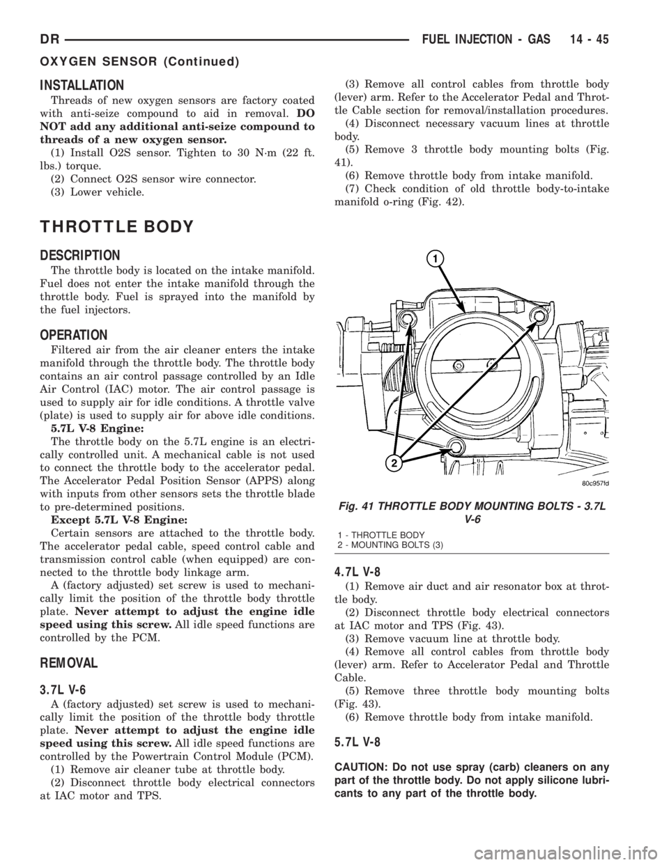
(5) Remove 3 throttle body mounting bolts (Fig.
41).
(6) Remove throttle body from intake manifold.
(7) Check condition of old throttle body-to-intake
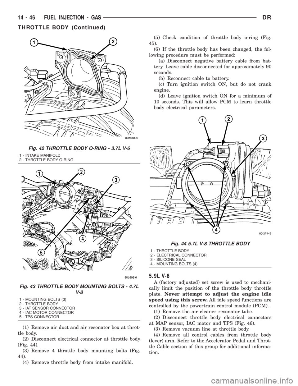
manifold o-ring (Fig. 42).
4.7L V-8
(1) Remove air duct and air resonator box at throt-
tle body.
(2) Disconnect throttle body electrical connectors
at IAC motor and TPS (Fig. 43).
(3) Remove vacuum line at throttle body.
(4) Remove all control cables from throttle body
(lever) arm. Refer to Accelerator Pedal and Throttle
Cable.
(5) Remove three throttle body mounting bolts
(Fig. 43).
(6) Remove throttle body from intake manifold.
5.7L V-8
CAUTION: Do not use spray (carb) cleaners on any
part of the throttle body. Do not apply silicone lubri-
cants to any part of the throttle body.
Fig. 41 THROTTLE BODY MOUNTING BOLTS - 3.7L
V-6
1 - THROTTLE BODY
2 - MOUNTING BOLTS (3)
DRFUEL INJECTION - GAS 14 - 45
OXYGEN SENSOR (Continued)
Page 1743 of 2895
(1) Remove air duct and air resonator box at throt-
tle body.
(2) Disconnect electrical connector at throttle body
(Fig. 44).
(3) Remove 4 throttle body mounting bolts (Fig.
44).
(4) Remove throttle body from intake manifold.(5) Check condition of throttle body o-ring (Fig.
45).
(6) If the throttle body has been changed, the fol-
lowing procedure must be performed:
(a) Disconnect negative battery cable from bat-
tery. Leave cable disconnected for approximately 90
seconds.
(b) Reconnect cable to battery.
(c) Turn ignition switch ON, but do not crank
engine.
(d) Leave ignition switch ON for a minimum of
10 seconds. This will allow PCM to learn throttle
body electrical parameters.
5.9L V-8
A (factory adjusted) set screw is used to mechani-
cally limit the position of the throttle body throttle
plate.Never attempt to adjust the engine idle
speed using this screw.All idle speed functions are
controlled by the powertrain control module (PCM).
(1) Remove the air cleaner resonator tube.
(2) Disconnect throttle body electrical connectors
at MAP sensor, IAC motor and TPS (Fig. 46).
(3) Remove vacuum line at throttle body.
(4) Remove all control cables from throttle body
(lever) arm. Refer to the Accelerator Pedal and Throt-
tle Cable section of this group for additional informa-
tion.
Fig. 42 THROTTLE BODY O-RING - 3.7L V-6
1 - INTAKE MANIFOLD
2 - THROTTLE BODY O-RING
Fig. 43 THROTTLE BODY MOUNTING BOLTS - 4.7L
V-8
1 - MOUNTING BOLTS (3)
2 - THROTTLE BODY
3 - IAT SENSOR CONNECTOR
4 - IAC MOTOR CONNECTOR
5 - TPS CONNECTOR
Fig. 44 5.7L V-8 THROTTLE BODY
1 - THROTTLE BODY
2 - ELECTRICAL CONNECTOR
3 - SILICONE SEAL
4 - MOUNTING BOLTS (4)
14 - 46 FUEL INJECTION - GASDR
THROTTLE BODY (Continued)
Page 1744 of 2895
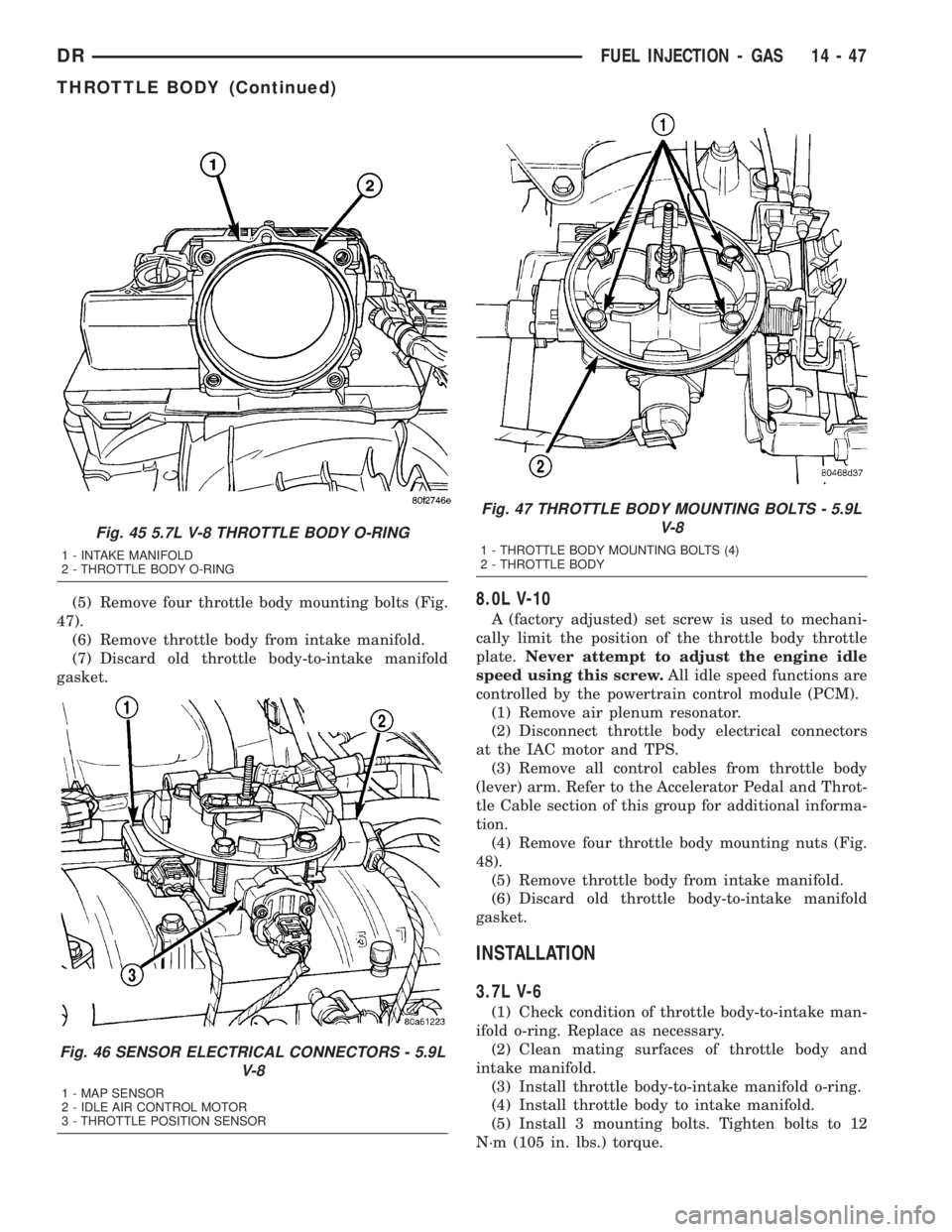
(5) Remove four throttle body mounting bolts (Fig.
47).
(6) Remove throttle body from intake manifold.
(7) Discard old throttle body-to-intake manifold
gasket.8.0L V-10
A (factory adjusted) set screw is used to mechani-
cally limit the position of the throttle body throttle
plate.Never attempt to adjust the engine idle
speed using this screw.All idle speed functions are
controlled by the powertrain control module (PCM).
(1) Remove air plenum resonator.
(2) Disconnect throttle body electrical connectors
at the IAC motor and TPS.
(3) Remove all control cables from throttle body
(lever) arm. Refer to the Accelerator Pedal and Throt-
tle Cable section of this group for additional informa-
tion.
(4) Remove four throttle body mounting nuts (Fig.
48).
(5) Remove throttle body from intake manifold.
(6) Discard old throttle body-to-intake manifold
gasket.
INSTALLATION
3.7L V-6
(1) Check condition of throttle body-to-intake man-
ifold o-ring. Replace as necessary.
(2) Clean mating surfaces of throttle body and
intake manifold.
(3) Install throttle body-to-intake manifold o-ring.
(4) Install throttle body to intake manifold.
(5) Install 3 mounting bolts. Tighten bolts to 12
N´m (105 in. lbs.) torque.
Fig. 45 5.7L V-8 THROTTLE BODY O-RING
1 - INTAKE MANIFOLD
2 - THROTTLE BODY O-RING
Fig. 46 SENSOR ELECTRICAL CONNECTORS - 5.9L
V-8
1 - MAP SENSOR
2 - IDLE AIR CONTROL MOTOR
3 - THROTTLE POSITION SENSOR
Fig. 47 THROTTLE BODY MOUNTING BOLTS - 5.9L
V-8
1 - THROTTLE BODY MOUNTING BOLTS (4)
2 - THROTTLE BODY
DRFUEL INJECTION - GAS 14 - 47
THROTTLE BODY (Continued)
Page 1745 of 2895
(6) Install control cables.
(7) Install electrical connectors.
(8) Install necessary vacuum lines.
(9) Install air plenum.
4.7L V-8
(1) Clean throttle body-to-intake manifold o-ring.
(2) Clean mating surfaces of throttle body and
intake manifold.
(3) Install throttle body to intake manifold by posi-
tioning throttle body to manifold alignment pins.
(4) Install three mounting bolts. Tighten bolts to
12 N´m (105 in. lbs.) torque.
(5) Install control cables.
(6) Install vacuum line to throttle body.
(7) Install electrical connectors.
(8) Install air plenum.
5.7L V-8
CAUTION: Do not use spray (carb) cleaners on any
part of the throttle body. Do not apply silicone lubri-
cants to any part of the throttle body.
(1) Clean and check condition of throttle body-to-
intake manifold o-ring.
(2) Clean mating surfaces of throttle body and
intake manifold.(3) Install throttle body to intake manifold by posi-
tioning throttle body to manifold alignment pins.
(4) Install 4 mounting bolts. Refer to Torque Spec-
ifications.
(5) Install electrical connector.
(6) Install air plenum.
(7)If the throttle body has been changed, the
following procedure must be performed:
(a) Disconnect negative battery cable from bat-
tery. Leave cable disconnected for approximately 90
seconds.
(b) Reconnect cable to battery.
(c) Turn ignition switch ON, but do not crank
engine.
(d) Leave ignition switch ON for a minimum of
10 seconds. This will allow PCM to learn throttle
body electrical parameters.
5.9L V-8
A (factory adjusted) set screw is used to mechani-
cally limit the position of the throttle body throttle
plate.Never attempt to adjust the engine idle
speed using this screw.All idle speed functions are
controlled by the powertrain control module (PCM).
(1) Clean the mating surfaces of the throttle body
and the intake manifold.
(2) Install new throttle body-to-intake manifold
gasket.
(3) Install throttle body to intake manifold.
(4) Install four mounting bolts. Tighten bolts to 23
N´m (200 in. lbs.) torque.
(5) Install control cables.
(6) Install vacuum line to throttle body.
(7) Install electrical connectors.
(8) Install air plenum.
8.0L V-10
A (factory adjusted) set screw is used to mechani-
cally limit the position of the throttle body throttle
plate.Never attempt to adjust the engine idle
speed using this screw.All idle speed functions are
controlled by the powertrain control module (PCM).
(1) Clean mating surfaces of throttle body and
intake manifold.
(2) Install new throttle body-to-intake manifold
gasket.
(3) Install throttle body to intake manifold.
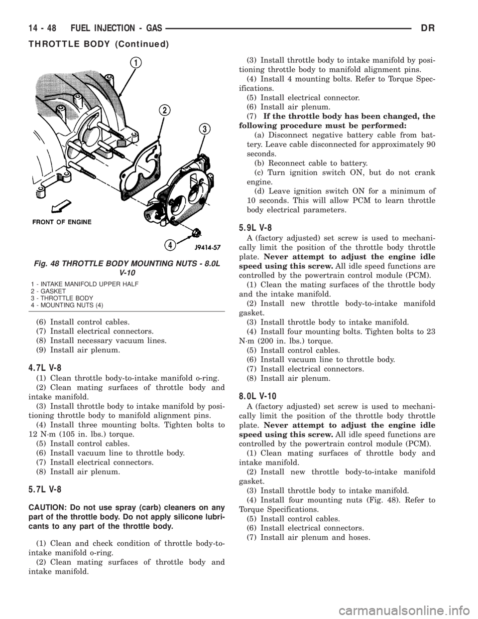
(4) Install four mounting nuts (Fig. 48). Refer to
Torque Specifications.
(5) Install control cables.
(6) Install electrical connectors.
(7) Install air plenum and hoses.
Fig. 48 THROTTLE BODY MOUNTING NUTS - 8.0L
V-10
1 - INTAKE MANIFOLD UPPER HALF
2 - GASKET
3 - THROTTLE BODY
4 - MOUNTING NUTS (4)
14 - 48 FUEL INJECTION - GASDR
THROTTLE BODY (Continued)
Page 1750 of 2895
The PCM supplies approximately 5 volts to the
TPS. The TPS output voltage (input signal to the
PCM) represents the throttle blade position. The
PCM receives an input signal voltage from the TPS.
This will vary in an approximate range of from .26
volts at minimum throttle opening (idle), to 4.49 volts
at wide open throttle. Along with inputs from other
sensors, the PCM uses the TPS input to determine
current engine operating conditions. In response to
engine operating conditions, the PCM will adjust fuel
injector pulse width and ignition timing.
The PCM needs to identify the actions and position
of the throttle blade at all times. This information is
needed to assist in performing the following calcula-
tions:
²Ignition timing advance
²Fuel injection pulse-width
²Idle (learned value or minimum TPS)
²Off-idle (0.06 volt)
²Wide Open Throttle (WOT) open loop (2.608
volts above learned idle voltage)
²Deceleration fuel lean out
²Fuel cutoff during cranking at WOT (2.608 volts
above learned idle voltage)
²A/C WOT cutoff (certain automatic transmis-
sions only)
REMOVAL
3.7L V6
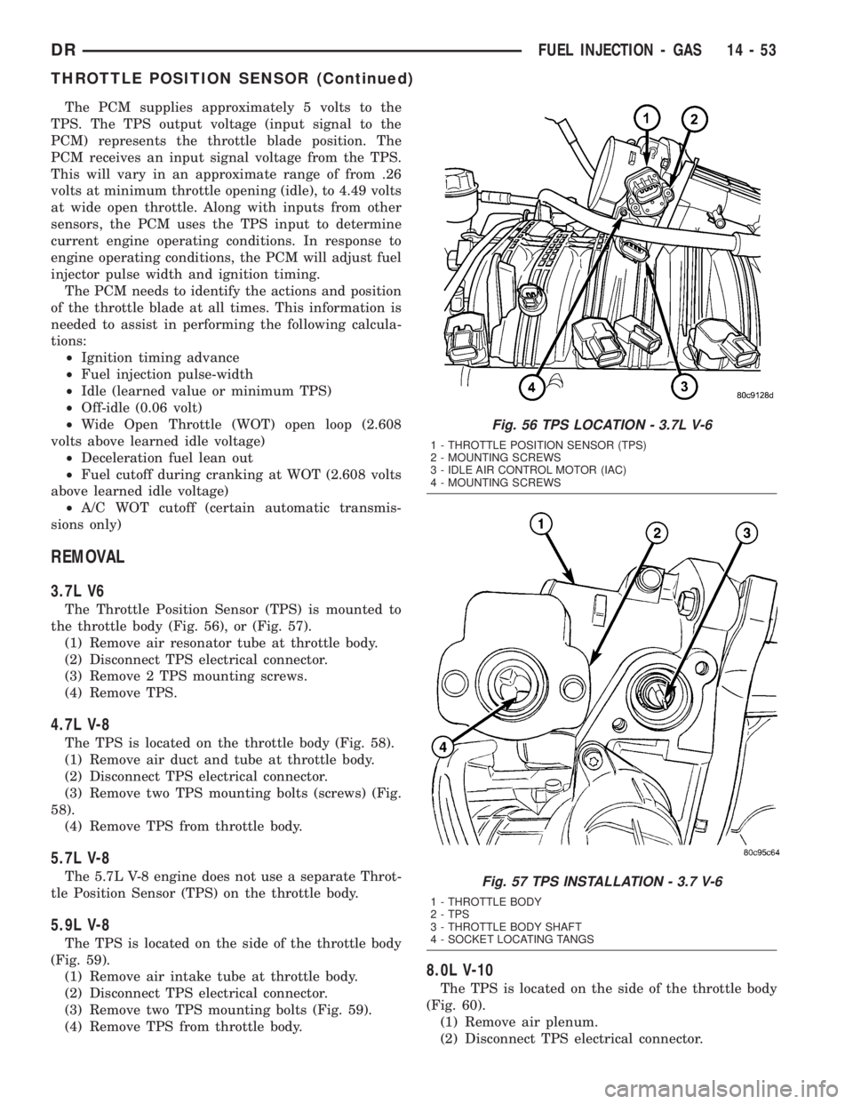
The Throttle Position Sensor (TPS) is mounted to
the throttle body (Fig. 56), or (Fig. 57).
(1) Remove air resonator tube at throttle body.
(2) Disconnect TPS electrical connector.
(3) Remove 2 TPS mounting screws.
(4) Remove TPS.
4.7L V-8
The TPS is located on the throttle body (Fig. 58).
(1) Remove air duct and tube at throttle body.
(2) Disconnect TPS electrical connector.
(3) Remove two TPS mounting bolts (screws) (Fig.
58).
(4) Remove TPS from throttle body.
5.7L V-8
The 5.7L V-8 engine does not use a separate Throt-
tle Position Sensor (TPS) on the throttle body.
5.9L V-8
The TPS is located on the side of the throttle body
(Fig. 59).
(1) Remove air intake tube at throttle body.
(2) Disconnect TPS electrical connector.
(3) Remove two TPS mounting bolts (Fig. 59).
(4) Remove TPS from throttle body.
8.0L V-10
The TPS is located on the side of the throttle body
(Fig. 60).
(1) Remove air plenum.
(2) Disconnect TPS electrical connector.
Fig. 56 TPS LOCATION - 3.7L V-6
1 - THROTTLE POSITION SENSOR (TPS)
2 - MOUNTING SCREWS
3 - IDLE AIR CONTROL MOTOR (IAC)
4 - MOUNTING SCREWS
Fig. 57 TPS INSTALLATION - 3.7 V-6
1 - THROTTLE BODY
2 - TPS
3 - THROTTLE BODY SHAFT
4 - SOCKET LOCATING TANGS
DRFUEL INJECTION - GAS 14 - 53
THROTTLE POSITION SENSOR (Continued)
Page 1751 of 2895
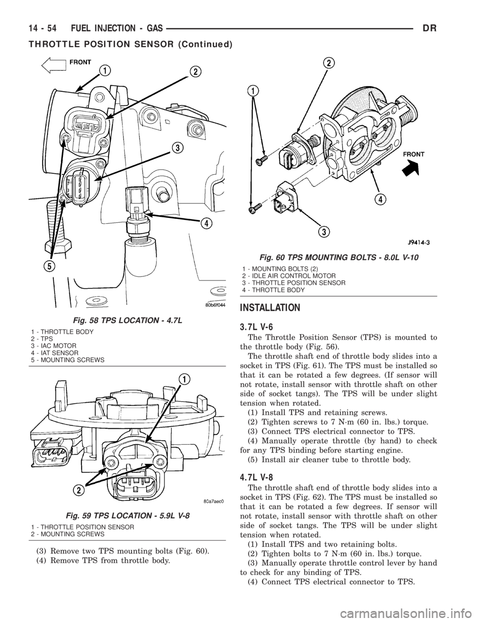
(3) Remove two TPS mounting bolts (Fig. 60).
(4) Remove TPS from throttle body.
INSTALLATION
3.7L V-6
The Throttle Position Sensor (TPS) is mounted to
the throttle body (Fig. 56).
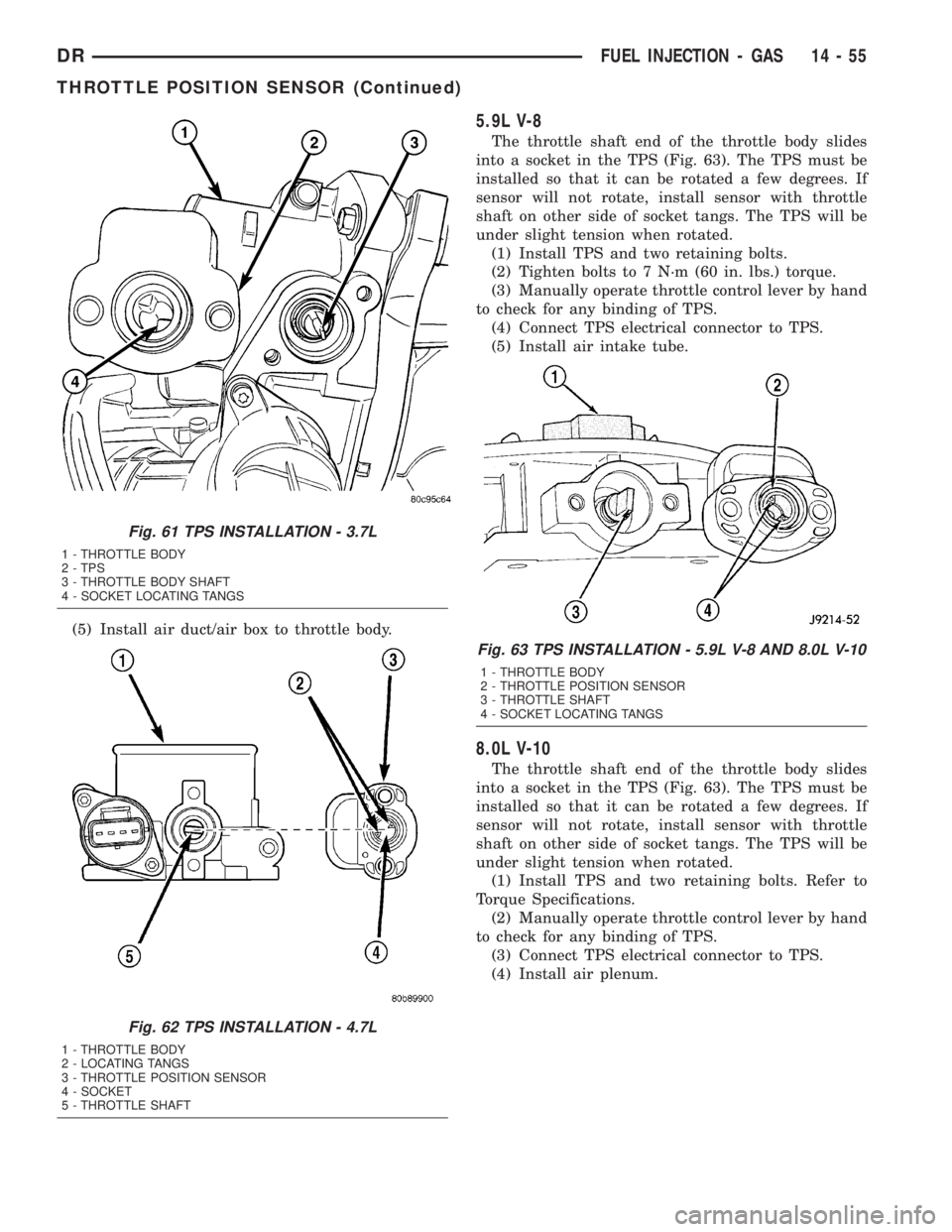
The throttle shaft end of throttle body slides into a
socket in TPS (Fig. 61). The TPS must be installed so
that it can be rotated a few degrees. (If sensor will
not rotate, install sensor with throttle shaft on other
side of socket tangs). The TPS will be under slight
tension when rotated.
(1) Install TPS and retaining screws.
(2) Tighten screws to 7 N´m (60 in. lbs.) torque.
(3) Connect TPS electrical connector to TPS.
(4) Manually operate throttle (by hand) to check
for any TPS binding before starting engine.
(5) Install air cleaner tube to throttle body.
4.7L V-8
The throttle shaft end of throttle body slides into a
socket in TPS (Fig. 62). The TPS must be installed so
that it can be rotated a few degrees. If sensor will
not rotate, install sensor with throttle shaft on other
side of socket tangs. The TPS will be under slight
tension when rotated.
(1) Install TPS and two retaining bolts.
(2) Tighten bolts to 7 N´m (60 in. lbs.) torque.
(3) Manually operate throttle control lever by hand
to check for any binding of TPS.
(4) Connect TPS electrical connector to TPS.
Fig. 58 TPS LOCATION - 4.7L
1 - THROTTLE BODY
2 - TPS
3 - IAC MOTOR
4 - IAT SENSOR
5 - MOUNTING SCREWS
Fig. 59 TPS LOCATION - 5.9L V-8
1 - THROTTLE POSITION SENSOR
2 - MOUNTING SCREWS
Fig. 60 TPS MOUNTING BOLTS - 8.0L V-10
1 - MOUNTING BOLTS (2)
2 - IDLE AIR CONTROL MOTOR
3 - THROTTLE POSITION SENSOR
4 - THROTTLE BODY
14 - 54 FUEL INJECTION - GASDR
THROTTLE POSITION SENSOR (Continued)
Page 1752 of 2895
(5) Install air duct/air box to throttle body.
5.9L V-8
The throttle shaft end of the throttle body slides
into a socket in the TPS (Fig. 63). The TPS must be
installed so that it can be rotated a few degrees. If
sensor will not rotate, install sensor with throttle
shaft on other side of socket tangs. The TPS will be
under slight tension when rotated.
(1) Install TPS and two retaining bolts.
(2) Tighten bolts to 7 N´m (60 in. lbs.) torque.
(3) Manually operate throttle control lever by hand
to check for any binding of TPS.
(4) Connect TPS electrical connector to TPS.
(5) Install air intake tube.
8.0L V-10
The throttle shaft end of the throttle body slides
into a socket in the TPS (Fig. 63). The TPS must be
installed so that it can be rotated a few degrees. If
sensor will not rotate, install sensor with throttle
shaft on other side of socket tangs. The TPS will be
under slight tension when rotated.
(1) Install TPS and two retaining bolts. Refer to
Torque Specifications.
(2) Manually operate throttle control lever by hand
to check for any binding of TPS.
(3) Connect TPS electrical connector to TPS.
(4) Install air plenum.
Fig. 61 TPS INSTALLATION - 3.7L
1 - THROTTLE BODY
2 - TPS
3 - THROTTLE BODY SHAFT
4 - SOCKET LOCATING TANGS
Fig. 62 TPS INSTALLATION - 4.7L
1 - THROTTLE BODY
2 - LOCATING TANGS
3 - THROTTLE POSITION SENSOR
4 - SOCKET
5 - THROTTLE SHAFT
Fig. 63 TPS INSTALLATION - 5.9L V-8 AND 8.0L V-10
1 - THROTTLE BODY
2 - THROTTLE POSITION SENSOR
3 - THROTTLE SHAFT
4 - SOCKET LOCATING TANGS
DRFUEL INJECTION - GAS 14 - 55
THROTTLE POSITION SENSOR (Continued)
Page 1758 of 2895
FUEL FILTER / WATER
SEPARATOR
DESCRIPTION
The fuel filter/water separator assembly is located
on left side of engine above starter motor. The assem-
bly also includes the fuel heater and Water-In-Fuel
(WIF) sensor, and fuel transfer pump.
OPERATION
The fuel filter/water separator protects the fuel
injection pump by removing water and contaminants
from the fuel. The construction of the filter/separator
allows fuel to pass through it, but helps prevent
moisture (water) from doing so. Moisture collects at
the bottom of the canister.
Refer to the maintenance schedules for the recom-
mended fuel filter replacement intervals.
For draining of water from canister, refer to Fuel
Filter/Water Separator Removal/Installation section.A Water-In-Fuel (WIF) sensor is attached to side of
canister. Refer to Water-In-Fuel Sensor Description/
Operation.
The fuel heater is installed into the top of the fil-
ter/separator housing. Refer to Fuel Heater Descrip-
tion/Operation.
REMOVAL
Refer to maintenance schedules in this manual for
recommended fuel filter replacement intervals.
Draining water from fuel filter/water separa-
tor housing:
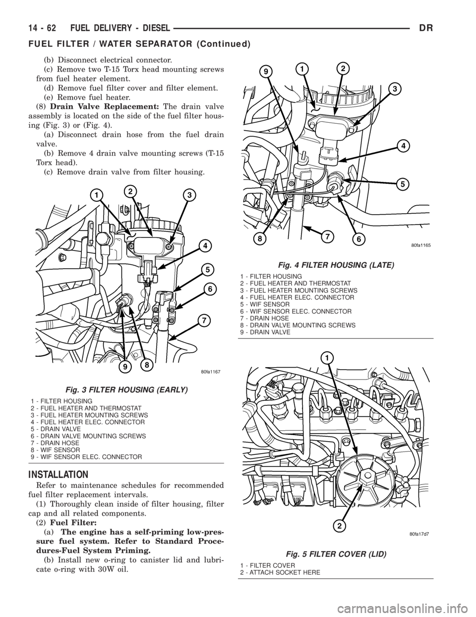
The housing drain valve (Fig. 3) or (Fig. 4) serves
two purposes. One is topartiallydrain filter hous-
ing of excess water. The other is tocompletelydrain
housing for fuel filter, drain valve, heater element, ,
water-in-fuel sensor replacement or transfer pump
replacement.
The filter housing should be partially drained
whenever water-in-fuel warning lamp remains illumi-
nated. (Note that lamp will be illuminated for
approximately two seconds when ignition key is ini-
tially placed in ON position for a bulb check).
(1) A drain hose (Fig. 3) or (Fig. 4) is located at
bottom of drain valve. Place drain pan under drain.
(2)With engine not running,rotate drain valve
handle rearward to OPEN (DRAIN) position. Hold
drain valve open until all water and contaminants
have been removed and clean fuel exits.
(3) If drain valve, fuel heater element or Water-In-
Fuel (WIF) sensor is being replaced, drain housing
completely. Dispose of mixture in drain pan according
to applicable regulations.
(4) After draining operation, push valve handle
forward to CLOSE position.
(5)Fuel Filter Replacement:The fuel filter is
located inside of the fuel filter housing.
(a) Clean all debris from around canister.
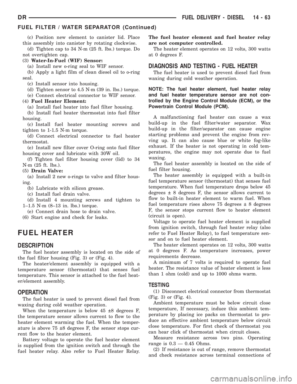
(b) Remove filter lid (Fig. 5) using a socket.
Attach socket to large hex on top of lid (Fig. 5).
Rotate counter-clockwise for removal. Remove
o-ring.
(c) Remove filter element by twisting element
sideways from filter lid.
(6)Water-In-Fuel (WIF) Sensor Replacement:
The WIF sensor is located on the side of the fuel fil-
ter housing (Fig. 3) or (Fig. 4).
(a) Disconnect electrical connector at sensor.
(b) Clean area around sensor.
(c) Remove sensor by rotating counter-clockwise.
(d) Check condition of sensor o-ring. Replace if
damaged.
(7)Fuel Heater Element Replacement:The
heater element is located in the fuel filter housing
(Fig. 3) or (Fig. 4).
(a) Remove fuel filter. See previous steps.
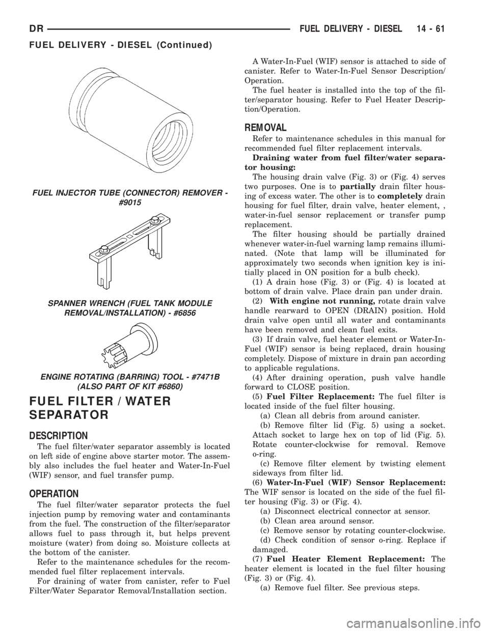
FUEL INJECTOR TUBE (CONNECTOR) REMOVER -
#9015
SPANNER WRENCH (FUEL TANK MODULE
REMOVAL/INSTALLATION) - #6856
ENGINE ROTATING (BARRING) TOOL - #7471B
(ALSO PART OF KIT #6860)
DRFUEL DELIVERY - DIESEL 14 - 61
FUEL DELIVERY - DIESEL (Continued)
Page 1759 of 2895
(b) Disconnect electrical connector.
(c) Remove two T-15 Torx head mounting screws
from fuel heater element.
(d) Remove fuel filter cover and filter element.
(e) Remove fuel heater.
(8)Drain Valve Replacement:The drain valve
assembly is located on the side of the fuel filter hous-
ing (Fig. 3) or (Fig. 4).
(a) Disconnect drain hose from the fuel drain
valve.
(b) Remove 4 drain valve mounting screws (T-15
Torx head).
(c) Remove drain valve from filter housing.
INSTALLATION
Refer to maintenance schedules for recommended
fuel filter replacement intervals.
(1) Thoroughly clean inside of filter housing, filter
cap and all related components.
(2)Fuel Filter:
(a)The engine has a self-priming low-pres-
sure fuel system. Refer to Standard Proce-
dures-Fuel System Priming.
(b) Install new o-ring to canister lid and lubri-
cate o-ring with 30W oil.
Fig. 3 FILTER HOUSING (EARLY)
1 - FILTER HOUSING
2 - FUEL HEATER AND THERMOSTAT
3 - FUEL HEATER MOUNTING SCREWS
4 - FUEL HEATER ELEC. CONNECTOR
5 - DRAIN VALVE
6 - DRAIN VALVE MOUNTING SCREWS
7 - DRAIN HOSE
8 - WIF SENSOR
9 - WIF SENSOR ELEC. CONNECTOR
Fig. 4 FILTER HOUSING (LATE)
1 - FILTER HOUSING
2 - FUEL HEATER AND THERMOSTAT
3 - FUEL HEATER MOUNTING SCREWS
4 - FUEL HEATER ELEC. CONNECTOR
5 - WIF SENSOR
6 - WIF SENSOR ELEC. CONNECTOR
7 - DRAIN HOSE
8 - DRAIN VALVE MOUNTING SCREWS
9 - DRAIN VALVE
Fig. 5 FILTER COVER (LID)
1 - FILTER COVER
2 - ATTACH SOCKET HERE
14 - 62 FUEL DELIVERY - DIESELDR
FUEL FILTER / WATER SEPARATOR (Continued)
Page 1760 of 2895
(c) Position new element to canister lid. Place
this assembly into canister by rotating clockwise.
(d) Tighten cap to 34 N´m (25 ft. lbs.) torque. Do
not overtighten cap.
(3)Water-In-Fuel (WIF) Sensor:
(a) Install new o-ring seal to WIF sensor.
(b) Apply a light film of clean diesel oil to o-ring
seal.
(c) Install sensor into housing.
(d) Tighten sensor to 4.5 N´m (39 in. lbs.) torque.
(e) Connect electrical connector to WIF sensor.
(4)Fuel Heater Element:
(a) Install fuel heater into fuel filter housing.
(b) Install fuel heater thermostat into fuel filter
housing.
(c) Install fuel heater mounting screws and
tighten to 1-1.5 N´m torque.
(d) Connect electrical connector to fuel heater
thermostat.
(e) Install new filter cover O-ring onto fuel filter
housing cover and lubricate with 30W oil.
(f) Tighten fuel filter housing cover (lid) to 34
N´m (25 ft. lbs.).
(5)Drain Valve:
(a) Install 2 new o-rings to valve and filter hous-
ing.
(b) Lubricate with silicon grease.
(c) Install fuel drain valve.
(d) Install 4 mounting screws and tighten to
1±1.5 N´m (8±13 in. lbs.) torque.
(e) Connect drain hose to drain valve.
(6) Start engine and check for leaks.
FUEL HEATER
DESCRIPTION
The fuel heater assembly is located on the side of
the fuel filter housing (Fig. 3) or (Fig. 4).
The heater/element assembly is equipped with a
temperature sensor (thermostat) that senses fuel
temperature. This sensor is attached to the fuel heat-
er/element assembly.
OPERATION
The fuel heater is used to prevent diesel fuel from
waxing during cold weather operation.
When the temperature is below 45 8 degrees F,
the temperature sensor allows current to flow to the
heater element warming the fuel. When the temper-
ature is above 75 8 degrees F, the sensor stops cur-
rent flow to the heater element.
Battery voltage to operate the fuel heater element
is supplied from the ignition switch and through the
fuel heater relay. Also refer to Fuel Heater Relay.The fuel heater element and fuel heater relay
are not computer controlled.
The heater element operates on 12 volts, 300 watts
at 0 degrees F.
DIAGNOSIS AND TESTING - FUEL HEATER
The fuel heater is used to prevent diesel fuel from
waxing during cold weather operation.
NOTE: The fuel heater element, fuel heater relay
and fuel heater temperature sensor are not con-
trolled by the Engine Control Module (ECM), or the
Powertrain Control Module (PCM).
A malfunctioning fuel heater can cause a wax
build-up in the fuel filter/water separator. Wax
build-up in the filter/separator can cause engine
starting problems and prevent the engine from rev-
ving up. It can also cause blue or white fog-like
exhaust. If the heater is not operating in cold tem-
peratures, the engine may not operate due to fuel
waxing.
The fuel heater assembly is located on the side of
fuel filter housing.
The heater assembly is equipped with a built-in
fuel temperature sensor (thermostat) that senses fuel
temperature. When fuel temperature drops below 45
degrees 8 degrees F, the sensor allows current to
flow to built-in heater element to warm fuel. When
fuel temperature rises above 75 degrees 8 degrees
F, the sensor stops current flow to heater element
(circuit is open).
Voltage to operate fuel heater element is supplied
from ignition switch, through fuel heater relay (also
refer to Fuel Heater Relay), to fuel temperature sen-
sor and on to fuel heater element.
The heater element operates on 12 volts, 300 watts
at 0 degrees F. As temperature increases, power
requirements decrease.
A minimum of 7 volts is required to operate fuel
heater. The resistance value of heater element is less
than 1 ohm (cold) and up to 1000 ohms warm.
TESTING
(1) Disconnect electrical connector from thermostat
(Fig. 3) or (Fig. 4).
Ambient temperature must be below circuit close
temperature, If necessary, induce this ambient tem-
perature by placing ice packs on thermostat to pro-
duce an effective ambient temperature below circuit
close temperature. For first check of thermostat you
can hear click of thermostat when circuit closes.
Measure resistance across two pins. Operating
range is 0.3 Ð 0.45 Ohms.
(2) If resistance is out of range, remove thermostat
and check resistance across terminal connections of
DRFUEL DELIVERY - DIESEL 14 - 63
FUEL FILTER / WATER SEPARATOR (Continued)