DODGE RAM 2003 Service Repair Manual
Manufacturer: DODGE, Model Year: 2003, Model line: RAM, Model: DODGE RAM 2003Pages: 2895, PDF Size: 83.15 MB
Page 611 of 2895
AIRBAG CONTROL MODULE
DESCRIPTION
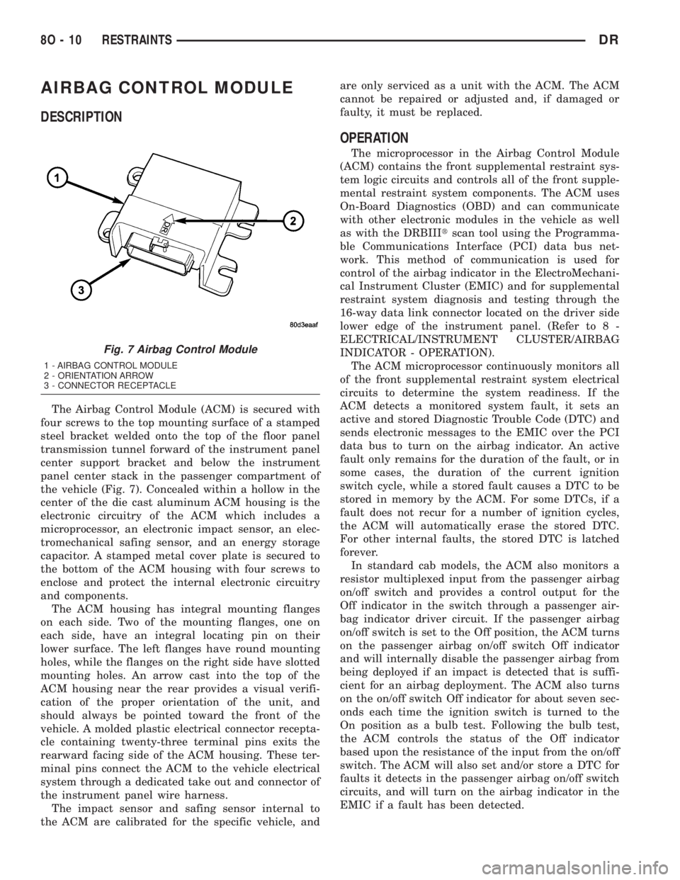
The Airbag Control Module (ACM) is secured with
four screws to the top mounting surface of a stamped
steel bracket welded onto the top of the floor panel
transmission tunnel forward of the instrument panel
center support bracket and below the instrument
panel center stack in the passenger compartment of
the vehicle (Fig. 7). Concealed within a hollow in the
center of the die cast aluminum ACM housing is the
electronic circuitry of the ACM which includes a
microprocessor, an electronic impact sensor, an elec-
tromechanical safing sensor, and an energy storage
capacitor. A stamped metal cover plate is secured to
the bottom of the ACM housing with four screws to
enclose and protect the internal electronic circuitry
and components.
The ACM housing has integral mounting flanges
on each side. Two of the mounting flanges, one on
each side, have an integral locating pin on their
lower surface. The left flanges have round mounting
holes, while the flanges on the right side have slotted
mounting holes. An arrow cast into the top of the
ACM housing near the rear provides a visual verifi-
cation of the proper orientation of the unit, and
should always be pointed toward the front of the
vehicle. A molded plastic electrical connector recepta-
cle containing twenty-three terminal pins exits the
rearward facing side of the ACM housing. These ter-
minal pins connect the ACM to the vehicle electrical
system through a dedicated take out and connector of
the instrument panel wire harness.
The impact sensor and safing sensor internal to
the ACM are calibrated for the specific vehicle, andare only serviced as a unit with the ACM. The ACM
cannot be repaired or adjusted and, if damaged or
faulty, it must be replaced.
OPERATION
The microprocessor in the Airbag Control Module
(ACM) contains the front supplemental restraint sys-
tem logic circuits and controls all of the front supple-
mental restraint system components. The ACM uses
On-Board Diagnostics (OBD) and can communicate
with other electronic modules in the vehicle as well
as with the DRBIIItscan tool using the Programma-
ble Communications Interface (PCI) data bus net-
work. This method of communication is used for
control of the airbag indicator in the ElectroMechani-
cal Instrument Cluster (EMIC) and for supplemental
restraint system diagnosis and testing through the
16-way data link connector located on the driver side
lower edge of the instrument panel. (Refer to 8 -
ELECTRICAL/INSTRUMENT CLUSTER/AIRBAG
INDICATOR - OPERATION).
The ACM microprocessor continuously monitors all
of the front supplemental restraint system electrical
circuits to determine the system readiness. If the
ACM detects a monitored system fault, it sets an
active and stored Diagnostic Trouble Code (DTC) and
sends electronic messages to the EMIC over the PCI
data bus to turn on the airbag indicator. An active
fault only remains for the duration of the fault, or in
some cases, the duration of the current ignition
switch cycle, while a stored fault causes a DTC to be
stored in memory by the ACM. For some DTCs, if a
fault does not recur for a number of ignition cycles,
the ACM will automatically erase the stored DTC.
For other internal faults, the stored DTC is latched
forever.
In standard cab models, the ACM also monitors a
resistor multiplexed input from the passenger airbag
on/off switch and provides a control output for the
Off indicator in the switch through a passenger air-
bag indicator driver circuit. If the passenger airbag
on/off switch is set to the Off position, the ACM turns
on the passenger airbag on/off switch Off indicator
and will internally disable the passenger airbag from
being deployed if an impact is detected that is suffi-
cient for an airbag deployment. The ACM also turns
on the on/off switch Off indicator for about seven sec-
onds each time the ignition switch is turned to the
On position as a bulb test. Following the bulb test,
the ACM controls the status of the Off indicator
based upon the resistance of the input from the on/off
switch. The ACM will also set and/or store a DTC for
faults it detects in the passenger airbag on/off switch
circuits, and will turn on the airbag indicator in the
EMIC if a fault has been detected.
Fig. 7 Airbag Control Module
1 - AIRBAG CONTROL MODULE
2 - ORIENTATION ARROW
3 - CONNECTOR RECEPTACLE
8O - 10 RESTRAINTSDR
Page 612 of 2895
On models equipped with optional side curtain air-
bags, the ACM communicates with both the left and
right Side Impact Airbag Control Modules (SIACM)
over the PCI data bus. The SIACM notifies the ACM
when it has detected a monitored system fault and
stored a DTC in memory for its respective side cur-
tain airbag system, and the ACM sets a DTC and
controls the airbag indicator operation accordingly.
The ACM receives battery current through two cir-
cuits; a fused ignition switch output (run) circuit
through a fuse in the Integrated Power Module
(IPM), and a fused ignition switch output (run-start)
circuit through a second fuse in the IPM. The ACM
receives ground through a ground circuit and take
out of the instrument panel wire harness. This take
out has a single eyelet terminal connector that is
secured by a ground screw to the instrument panel
support structure. These connections allow the ACM
to be operational whenever the ignition switch is in
the Start or On positions. The ACM also contains an
energy-storage capacitor. When the ignition switch is
in the Start or On positions, this capacitor is contin-
ually being charged with enough electrical energy to
deploy the front supplemental restraint components
for up to one second following a battery disconnect or
failure. The purpose of the capacitor is to provide
backup supplemental restraint system protection in
case there is a loss of battery current supply to the
ACM during an impact.
Two sensors are contained within the ACM; an
electronic impact sensor, and a safing sensor. The
electronic impact sensor is an accelerometer that
senses the rate of vehicle deceleration, which pro-
vides verification of the direction and severity of an
impact. The safing sensor is an electromechanical
sensor within the ACM that provides an additional
logic input to the ACM microprocessor. The safing
sensor is a normally open switch that is used to ver-
ify the need for a front supplemental restraint
deployment by detecting impact energy of a lesser
magnitude than that of the electronic impact sensor,
and must be closed in order for the front airbags or
seat belt tensioners to deploy. A pre-programmed
decision algorithm in the ACM microprocessor deter-
mines when the deceleration rate as signaled by the
impact sensor and the safing sensor indicate an
impact that is severe enough to require front supple-
mental restraint system protection and, based upon
the status of the passenger airbag on/off switch input
and the severity of the monitored impact, determines
what combination of seat belt tensioner and front air-
bag deployment is required for each front seating
position. When the programmed conditions are met,
the ACM sends the proper electrical signals to deploy
the seat belt tensioners and dual front airbags.The hard wired inputs and outputs for the ACM
may be diagnosed and tested using conventional
diagnostic tools and procedures. However, conven-
tional diagnostic methods will not prove conclusive in
the diagnosis of the ACM, the PCI data bus network,
or the electronic message inputs to and outputs from
the ACM. The most reliable, efficient, and accurate
means to diagnose the ACM, the PCI data bus net-
work, and the electronic message inputs to and out-
puts from the ACM requires the use of a DRBIIIt
scan tool. Refer to the appropriate diagnostic infor-
mation.
REMOVAL
WARNING: ON VEHICLES EQUIPPED WITH AIR-
BAGS, DISABLE THE SUPPLEMENTAL RESTRAINT
SYSTEM BEFORE ATTEMPTING ANY STEERING
WHEEL, STEERING COLUMN, DRIVER AIRBAG,
PASSENGER AIRBAG, SEAT BELT TENSIONER,
SIDE CURTAIN AIRBAG, OR INSTRUMENT PANEL
COMPONENT DIAGNOSIS OR SERVICE. DISCON-
NECT AND ISOLATE THE BATTERY NEGATIVE
(GROUND) CABLE, THEN WAIT TWO MINUTES FOR
THE SYSTEM CAPACITOR TO DISCHARGE BEFORE
PERFORMING FURTHER DIAGNOSIS OR SERVICE.
THIS IS THE ONLY SURE WAY TO DISABLE THE
SUPPLEMENTAL RESTRAINT SYSTEM. FAILURE TO
TAKE THE PROPER PRECAUTIONS COULD
RESULT IN ACCIDENTAL AIRBAG DEPLOYMENT
AND POSSIBLE PERSONAL INJURY.
WARNING: THE AIRBAG CONTROL MODULE CON-
TAINS THE IMPACT SENSOR, WHICH ENABLES
THE SYSTEM TO DEPLOY THE FRONT SUPPLE-
MENTAL RESTRAINTS. NEVER STRIKE OR DROP
THE AIRBAG CONTROL MODULE, AS IT CAN DAM-
AGE THE IMPACT SENSOR OR AFFECT ITS CALI-
BRATION. IF AN AIRBAG CONTROL MODULE IS
ACCIDENTALLY DROPPED DURING SERVICE, THE
MODULE MUST BE SCRAPPED AND REPLACED
WITH A NEW UNIT. FAILURE TO OBSERVE THIS
WARNING COULD RESULT IN ACCIDENTAL,
INCOMPLETE, OR IMPROPER FRONT SUPPLEMEN-
TAL RESTRAINT DEPLOYMENT AND POSSIBLE
OCCUPANT INJURIES.
(1) Disconnect and isolate the battery negative
cable. Wait two minutes for the system capacitor to
discharge before further service.
(2) On models with a manual transmission,
remove the floor console from the top of the floor
panel transmission tunnel. (Refer to 23 - BODY/IN-
TERIOR/FLOOR CONSOLE - REMOVAL).
(3) On models with an automatic transmission,
remove the ACM cover from the instrument panel.
DRRESTRAINTS 8O - 11
AIRBAG CONTROL MODULE (Continued)
Page 613 of 2895
(Refer to 8 - ELECTRICAL/RESTRAINTS/ACM
COVER - REMOVAL).
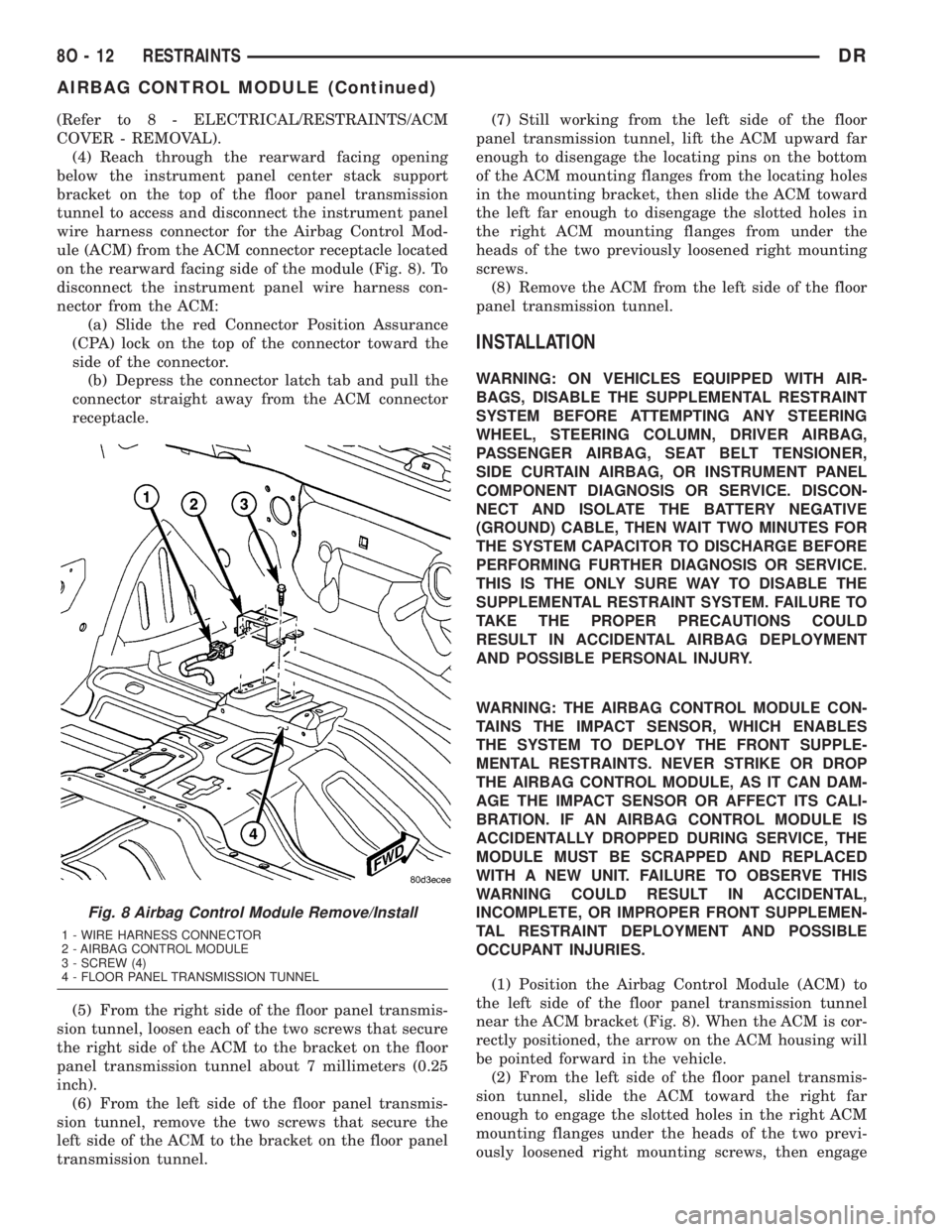
(4) Reach through the rearward facing opening
below the instrument panel center stack support
bracket on the top of the floor panel transmission
tunnel to access and disconnect the instrument panel
wire harness connector for the Airbag Control Mod-
ule (ACM) from the ACM connector receptacle located
on the rearward facing side of the module (Fig. 8). To
disconnect the instrument panel wire harness con-
nector from the ACM:
(a) Slide the red Connector Position Assurance
(CPA) lock on the top of the connector toward the
side of the connector.
(b) Depress the connector latch tab and pull the
connector straight away from the ACM connector
receptacle.
(5) From the right side of the floor panel transmis-
sion tunnel, loosen each of the two screws that secure
the right side of the ACM to the bracket on the floor
panel transmission tunnel about 7 millimeters (0.25
inch).
(6) From the left side of the floor panel transmis-
sion tunnel, remove the two screws that secure the
left side of the ACM to the bracket on the floor panel
transmission tunnel.(7) Still working from the left side of the floor
panel transmission tunnel, lift the ACM upward far
enough to disengage the locating pins on the bottom
of the ACM mounting flanges from the locating holes
in the mounting bracket, then slide the ACM toward
the left far enough to disengage the slotted holes in
the right ACM mounting flanges from under the
heads of the two previously loosened right mounting
screws.
(8) Remove the ACM from the left side of the floor
panel transmission tunnel.
INSTALLATION
WARNING: ON VEHICLES EQUIPPED WITH AIR-
BAGS, DISABLE THE SUPPLEMENTAL RESTRAINT
SYSTEM BEFORE ATTEMPTING ANY STEERING
WHEEL, STEERING COLUMN, DRIVER AIRBAG,
PASSENGER AIRBAG, SEAT BELT TENSIONER,
SIDE CURTAIN AIRBAG, OR INSTRUMENT PANEL
COMPONENT DIAGNOSIS OR SERVICE. DISCON-
NECT AND ISOLATE THE BATTERY NEGATIVE
(GROUND) CABLE, THEN WAIT TWO MINUTES FOR
THE SYSTEM CAPACITOR TO DISCHARGE BEFORE
PERFORMING FURTHER DIAGNOSIS OR SERVICE.
THIS IS THE ONLY SURE WAY TO DISABLE THE
SUPPLEMENTAL RESTRAINT SYSTEM. FAILURE TO
TAKE THE PROPER PRECAUTIONS COULD
RESULT IN ACCIDENTAL AIRBAG DEPLOYMENT
AND POSSIBLE PERSONAL INJURY.
WARNING: THE AIRBAG CONTROL MODULE CON-
TAINS THE IMPACT SENSOR, WHICH ENABLES
THE SYSTEM TO DEPLOY THE FRONT SUPPLE-
MENTAL RESTRAINTS. NEVER STRIKE OR DROP
THE AIRBAG CONTROL MODULE, AS IT CAN DAM-
AGE THE IMPACT SENSOR OR AFFECT ITS CALI-
BRATION. IF AN AIRBAG CONTROL MODULE IS
ACCIDENTALLY DROPPED DURING SERVICE, THE
MODULE MUST BE SCRAPPED AND REPLACED
WITH A NEW UNIT. FAILURE TO OBSERVE THIS
WARNING COULD RESULT IN ACCIDENTAL,
INCOMPLETE, OR IMPROPER FRONT SUPPLEMEN-
TAL RESTRAINT DEPLOYMENT AND POSSIBLE
OCCUPANT INJURIES.
(1) Position the Airbag Control Module (ACM) to
the left side of the floor panel transmission tunnel
near the ACM bracket (Fig. 8). When the ACM is cor-
rectly positioned, the arrow on the ACM housing will
be pointed forward in the vehicle.
(2) From the left side of the floor panel transmis-
sion tunnel, slide the ACM toward the right far
enough to engage the slotted holes in the right ACM
mounting flanges under the heads of the two previ-
ously loosened right mounting screws, then engage
Fig. 8 Airbag Control Module Remove/Install
1 - WIRE HARNESS CONNECTOR
2 - AIRBAG CONTROL MODULE
3 - SCREW (4)
4 - FLOOR PANEL TRANSMISSION TUNNEL
8O - 12 RESTRAINTSDR
AIRBAG CONTROL MODULE (Continued)
Page 614 of 2895
the locating pins on the bottom of the ACM mounting
flanges into the locating holes in the bracket.
(3) Still working from the left side of the floor
panel transmission tunnel, install and tighten the
two screws that secure the left ACM mounting
flanges to the bracket that is welded onto the floor
panel transmission tunnel. Tighten the screws to 14
N´m (10 ft. lbs.).
(4) From the right side of the floor panel transmis-
sion tunnel, tighten each of the two screws that
secure the right side of the ACM to the bracket on
the floor panel transmission tunnel. Tighten the
screws to 14 N´m (10 ft. lbs.).
(5) Reach through the rearward facing opening
below the instrument panel center stack support
bracket on the top of the floor panel transmission
tunnel to access and reconnect the instrument panel
wire harness connector for the ACM to the ACM con-
nector receptacle located on the rearward facing side
of the module. Be certain that the latch and the red
Connector Position Assurance (CPA) lock on the con-
nector are each fully engaged.
(6) On models with an automatic transmission,
reinstall the ACM cover onto the instrument panel.
(Refer to 8 - ELECTRICAL/RESTRAINTS/ACM
COVER - INSTALLATION).
(7) On models with a manual transmission, rein-
stall the floor console onto the top of the floor panel
transmission tunnel. (Refer to 23 - BODY/INTERI-
OR/FLOOR CONSOLE - INSTALLATION).
(8) Do not reconnect the battery negative cable at
this time. The supplemental restraint system verifi-
cation test procedure should be performed following
service of any supplemental restraint system compo-
nent. (Refer to 8 - ELECTRICAL/RESTRAINTS -
STANDARD PROCEDURE - VERIFICATION TEST).AUTOMATIC LOCKING
RETRACTOR
DESCRIPTION
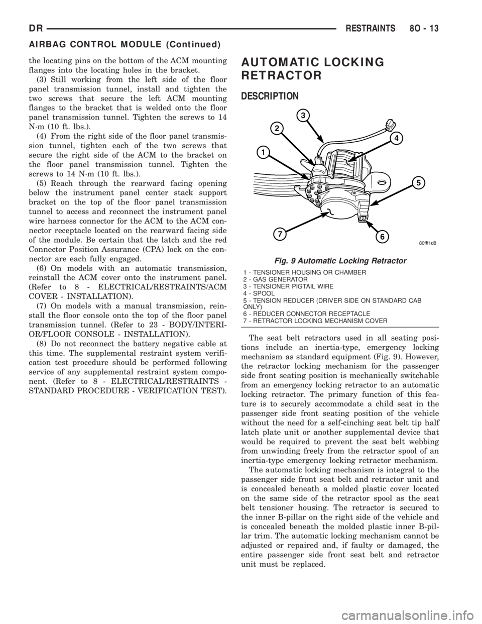
The seat belt retractors used in all seating posi-
tions include an inertia-type, emergency locking
mechanism as standard equipment (Fig. 9). However,
the retractor locking mechanism for the passenger
side front seating position is mechanically switchable
from an emergency locking retractor to an automatic
locking retractor. The primary function of this fea-
ture is to securely accommodate a child seat in the
passenger side front seating position of the vehicle
without the need for a self-cinching seat belt tip half
latch plate unit or another supplemental device that
would be required to prevent the seat belt webbing
from unwinding freely from the retractor spool of an
inertia-type emergency locking retractor mechanism.
The automatic locking mechanism is integral to the
passenger side front seat belt and retractor unit and
is concealed beneath a molded plastic cover located
on the same side of the retractor spool as the seat
belt tensioner housing. The retractor is secured to
the inner B-pillar on the right side of the vehicle and
is concealed beneath the molded plastic inner B-pil-
lar trim. The automatic locking mechanism cannot be
adjusted or repaired and, if faulty or damaged, the
entire passenger side front seat belt and retractor
unit must be replaced.
Fig. 9 Automatic Locking Retractor
1 - TENSIONER HOUSING OR CHAMBER
2 - GAS GENERATOR
3 - TENSIONER PIGTAIL WIRE
4 - SPOOL
5 - TENSION REDUCER (DRIVER SIDE ON STANDARD CAB
ONLY)
6 - REDUCER CONNECTOR RECEPTACLE
7 - RETRACTOR LOCKING MECHANISM COVER
DRRESTRAINTS 8O - 13
AIRBAG CONTROL MODULE (Continued)
Page 615 of 2895
OPERATION
The automatic locking mode of the retractor is
engaged and the retractor is switched from operating
as a standard inertia-type emergency locking retrac-
tor by first buckling the combination lap and shoul-
der belt buckle. Then grasp the shoulder belt and
pull all of the webbing out of the retractor. Once all
of the belt webbing is extracted from the spool, the
retractor will automatically become engaged in the
pre-locked automatic locking mode and will make an
audible clicking or ratcheting sound as the shoulder
belt is allowed to retract to confirm that the auto-
matic locking mode is now engaged. Once the auto-
matic locking mode is engaged, the retractor will
remain locked and the belt will remain tight around
whatever it is restraining.The retractor is returned to standard emergency
locking mode by unbuckling the combination lap and
shoulder belt buckle and allowing the belt webbing to
be almost fully retracted onto the retractor spool. The
emergency locking mode is confirmed by the absence
of the audible clicking or ratcheting sound as the belt
webbing retracts. This mode will allow the belt to
unwind from and wind onto the retractor spool freely
unless and until a predetermined inertia load is
sensed, or until the retractor is again switched to the
automatic locking mode.
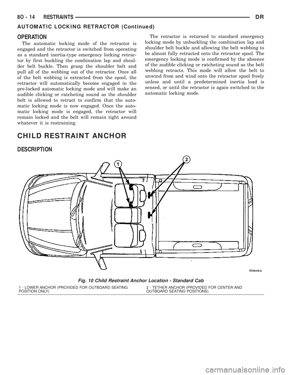
CHILD RESTRAINT ANCHOR
DESCRIPTION
Fig. 10 Child Restraint Anchor Location - Standard Cab
1 - LOWER ANCHOR (PROVIDED FOR OUTBOARD SEATING
POSITION ONLY)2 - TETHER ANCHOR (PROVIDED FOR CENTER AND
OUTBOARD SEATING POSITIONS)
8O - 14 RESTRAINTSDR
AUTOMATIC LOCKING RETRACTOR (Continued)
Page 616 of 2895
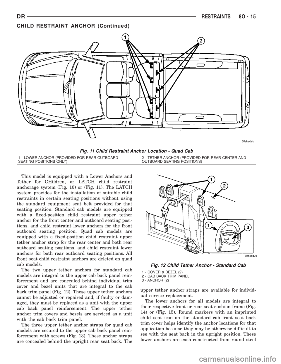
This model is equipped with a Lower Anchors and
Tether for CHildren, or LATCH child restraint
anchorage system (Fig. 10) or (Fig. 11). The LATCH
system provides for the installation of suitable child
restraints in certain seating positions without using
the standard equipment seat belt provided for that
seating position. Standard cab models are equipped
with a fixed-position child restraint upper tether
anchor for the front center and outboard seating posi-
tions, and child restraint lower anchors for the front
outboard seating position. Quad cab models are
equipped with a fixed-position child restraint upper
tether anchor strap for the rear center and both rear
outboard seating positions, and child restraint lower
anchors for both rear outboard seating positions. All
front seat child restraint anchors are deleted on quad
cab models.
The two upper tether anchors for standard cab
models are integral to the upper cab back panel rein-
forcement and are concealed behind individual trim
cover and bezel units that are integral to the cab
back trim panel (Fig. 12). These upper tether anchors
cannot be adjusted or repaired and, if faulty or dam-
aged, they must be replaced as a unit with the upper
cab back panel reinforcement. The upper tether
anchor trim covers and bezels are serviced as a unit
with the cab back trim panel.
The three upper tether anchor straps for quad cab
models are secured to the upper cab back panel rein-
forcement with screws (Fig. 13). These anchor straps
are concealed behind the upright rear seat back. Theupper tether anchor straps are available for individ-
ual service replacement.
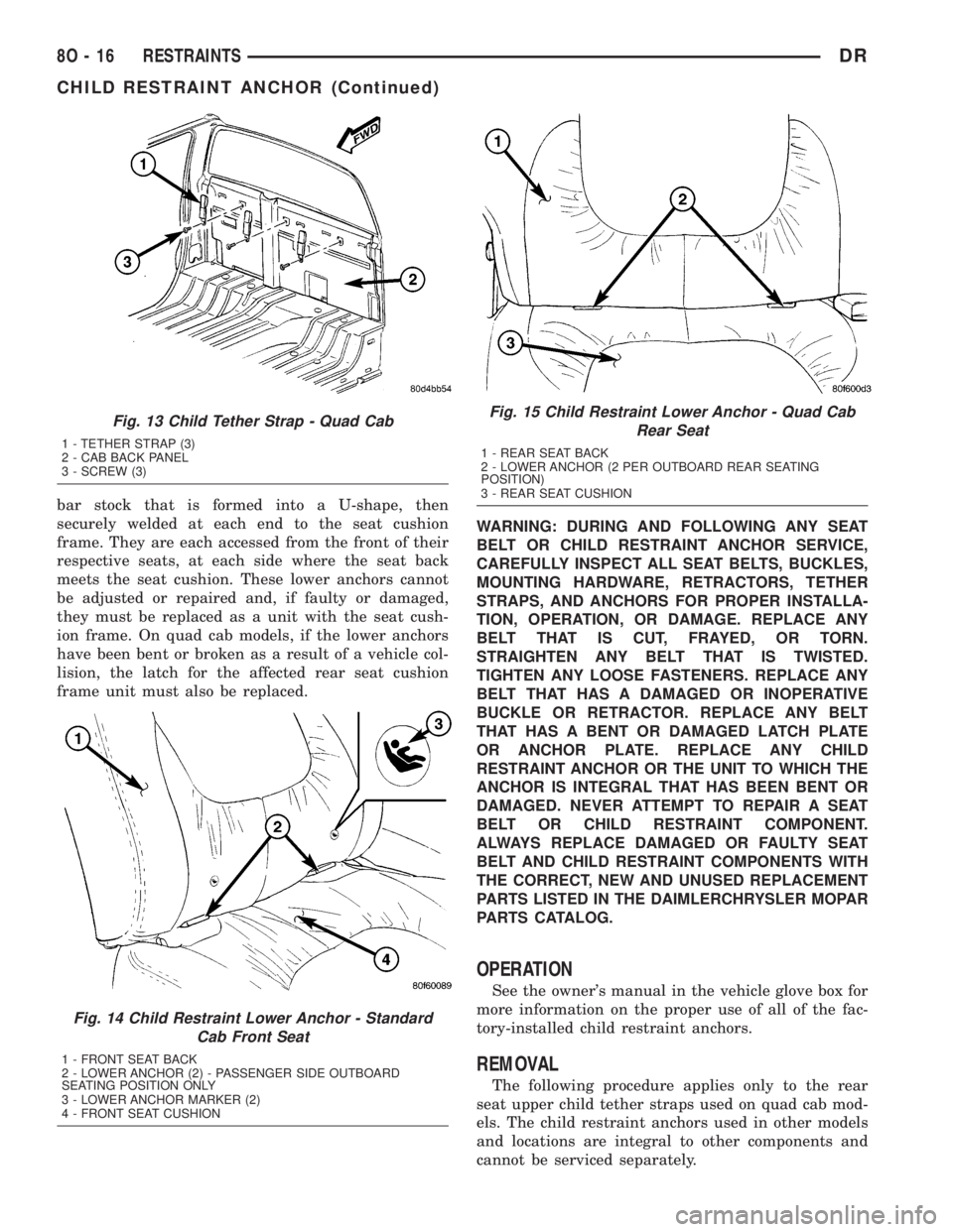
The lower anchors for all models are integral to
their respective front or rear seat cushion frame (Fig.
14) or (Fig. 15). Round markers with an imprinted
child seat icon on the standard cab front seat back
trim cover helps identify the anchor locations for that
application because they may be otherwise difficult to
see with the seat back in the upright position. These
lower anchors are each constructed from round steel
Fig. 11 Child Restraint Anchor Location - Quad Cab
1 - LOWER ANCHOR (PROVIDED FOR REAR OUTBOARD
SEATING POSITIONS ONLY)2 - TETHER ANCHOR (PROVIDED FOR REAR CENTER AND
OUTBOARD SEATING POSITIONS)
Fig. 12 Child Tether Anchor - Standard Cab
1 - COVER & BEZEL (2)
2 - CAB BACK TRIM PANEL
3 - ANCHOR (2)
DRRESTRAINTS 8O - 15
CHILD RESTRAINT ANCHOR (Continued)
Page 617 of 2895
bar stock that is formed into a U-shape, then
securely welded at each end to the seat cushion
frame. They are each accessed from the front of their
respective seats, at each side where the seat back
meets the seat cushion. These lower anchors cannot
be adjusted or repaired and, if faulty or damaged,
they must be replaced as a unit with the seat cush-
ion frame. On quad cab models, if the lower anchors
have been bent or broken as a result of a vehicle col-
lision, the latch for the affected rear seat cushion
frame unit must also be replaced.WARNING: DURING AND FOLLOWING ANY SEAT
BELT OR CHILD RESTRAINT ANCHOR SERVICE,
CAREFULLY INSPECT ALL SEAT BELTS, BUCKLES,
MOUNTING HARDWARE, RETRACTORS, TETHER
STRAPS, AND ANCHORS FOR PROPER INSTALLA-
TION, OPERATION, OR DAMAGE. REPLACE ANY
BELT THAT IS CUT, FRAYED, OR TORN.
STRAIGHTEN ANY BELT THAT IS TWISTED.
TIGHTEN ANY LOOSE FASTENERS. REPLACE ANY
BELT THAT HAS A DAMAGED OR INOPERATIVE
BUCKLE OR RETRACTOR. REPLACE ANY BELT
THAT HAS A BENT OR DAMAGED LATCH PLATE
OR ANCHOR PLATE. REPLACE ANY CHILD
RESTRAINT ANCHOR OR THE UNIT TO WHICH THE
ANCHOR IS INTEGRAL THAT HAS BEEN BENT OR
DAMAGED. NEVER ATTEMPT TO REPAIR A SEAT
BELT OR CHILD RESTRAINT COMPONENT.
ALWAYS REPLACE DAMAGED OR FAULTY SEAT
BELT AND CHILD RESTRAINT COMPONENTS WITH
THE CORRECT, NEW AND UNUSED REPLACEMENT
PARTS LISTED IN THE DAIMLERCHRYSLER MOPAR
PARTS CATALOG.
OPERATION
See the owner's manual in the vehicle glove box for
more information on the proper use of all of the fac-
tory-installed child restraint anchors.
REMOVAL
The following procedure applies only to the rear
seat upper child tether straps used on quad cab mod-
els. The child restraint anchors used in other models
and locations are integral to other components and
cannot be serviced separately.
Fig. 13 Child Tether Strap - Quad Cab
1 - TETHER STRAP (3)
2 - CAB BACK PANEL
3 - SCREW (3)
Fig. 14 Child Restraint Lower Anchor - Standard
Cab Front Seat
1 - FRONT SEAT BACK
2 - LOWER ANCHOR (2) - PASSENGER SIDE OUTBOARD
SEATING POSITION ONLY
3 - LOWER ANCHOR MARKER (2)
4 - FRONT SEAT CUSHION
Fig. 15 Child Restraint Lower Anchor - Quad Cab
Rear Seat
1 - REAR SEAT BACK
2 - LOWER ANCHOR (2 PER OUTBOARD REAR SEATING
POSITION)
3 - REAR SEAT CUSHION
8O - 16 RESTRAINTSDR
CHILD RESTRAINT ANCHOR (Continued)
Page 618 of 2895
WARNING: DURING AND FOLLOWING ANY SEAT
BELT OR CHILD RESTRAINT ANCHOR SERVICE,
CAREFULLY INSPECT ALL SEAT BELTS, BUCKLES,
MOUNTING HARDWARE, RETRACTORS, TETHER
STRAPS, AND ANCHORS FOR PROPER INSTALLA-
TION, OPERATION, OR DAMAGE. REPLACE ANY
BELT THAT IS CUT, FRAYED, OR TORN.
STRAIGHTEN ANY BELT THAT IS TWISTED.
TIGHTEN ANY LOOSE FASTENERS. REPLACE ANY
BELT THAT HAS A DAMAGED OR INOPERATIVE
BUCKLE OR RETRACTOR. REPLACE ANY BELT
THAT HAS A BENT OR DAMAGED LATCH PLATE
OR ANCHOR PLATE. REPLACE ANY CHILD
RESTRAINT ANCHOR OR THE UNIT TO WHICH THE
ANCHOR IS INTEGRAL THAT HAS BEEN BENT OR
DAMAGED. NEVER ATTEMPT TO REPAIR A SEAT
BELT OR CHILD RESTRAINT COMPONENT.
ALWAYS REPLACE DAMAGED OR FAULTY SEAT
BELT AND CHILD RESTRAINT COMPONENTS WITH
THE CORRECT, NEW AND UNUSED REPLACEMENT
PARTS LISTED IN THE DAIMLERCHRYSLER MOPAR
PARTS CATALOG.
(1) Remove the rear seat from the vehicle. (Refer
to 23 - BODY/SEATS/SEAT - REAR - REMOVAL).
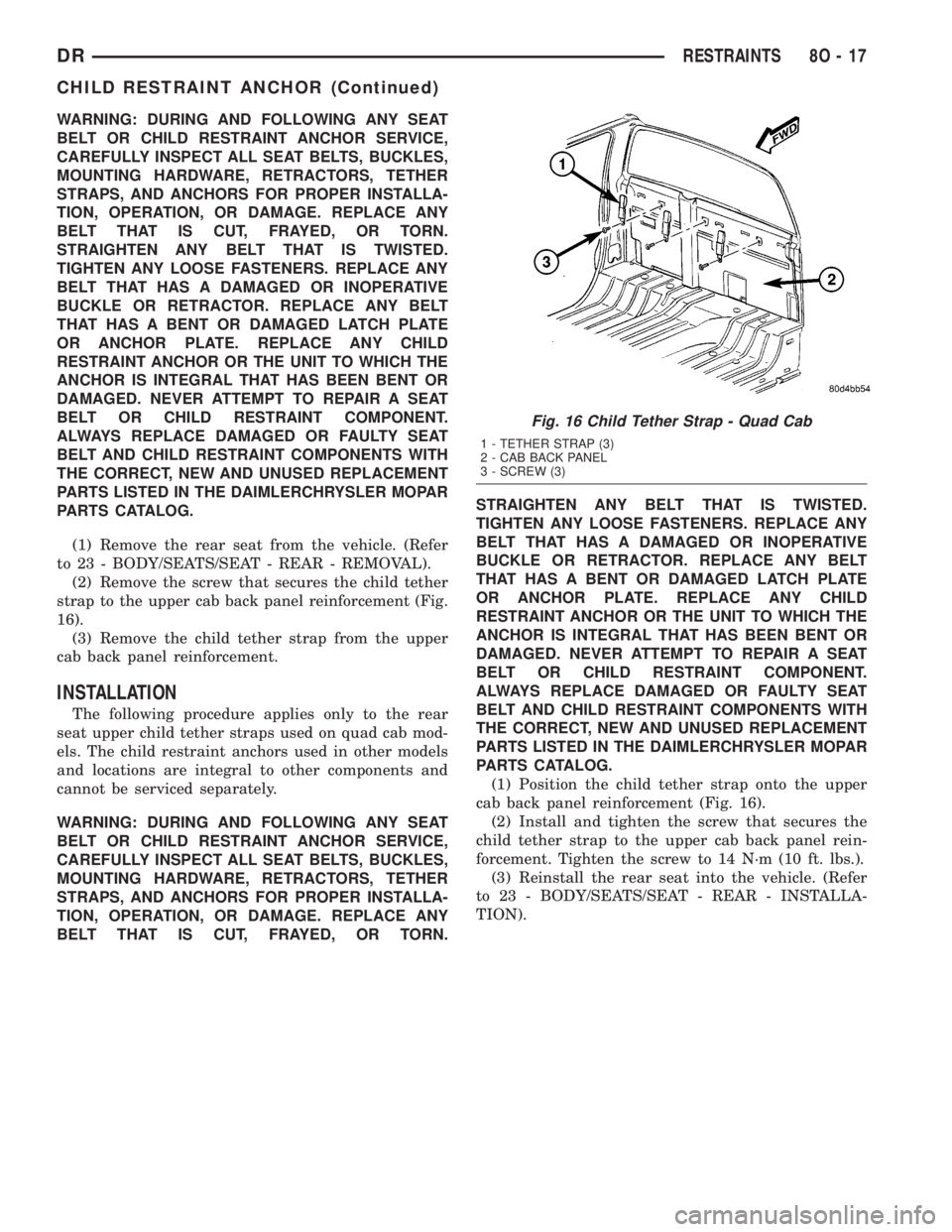
(2) Remove the screw that secures the child tether
strap to the upper cab back panel reinforcement (Fig.
16).
(3) Remove the child tether strap from the upper
cab back panel reinforcement.
INSTALLATION
The following procedure applies only to the rear
seat upper child tether straps used on quad cab mod-
els. The child restraint anchors used in other models
and locations are integral to other components and
cannot be serviced separately.
WARNING: DURING AND FOLLOWING ANY SEAT
BELT OR CHILD RESTRAINT ANCHOR SERVICE,
CAREFULLY INSPECT ALL SEAT BELTS, BUCKLES,
MOUNTING HARDWARE, RETRACTORS, TETHER
STRAPS, AND ANCHORS FOR PROPER INSTALLA-
TION, OPERATION, OR DAMAGE. REPLACE ANY
BELT THAT IS CUT, FRAYED, OR TORN.STRAIGHTEN ANY BELT THAT IS TWISTED.
TIGHTEN ANY LOOSE FASTENERS. REPLACE ANY
BELT THAT HAS A DAMAGED OR INOPERATIVE
BUCKLE OR RETRACTOR. REPLACE ANY BELT
THAT HAS A BENT OR DAMAGED LATCH PLATE
OR ANCHOR PLATE. REPLACE ANY CHILD
RESTRAINT ANCHOR OR THE UNIT TO WHICH THE
ANCHOR IS INTEGRAL THAT HAS BEEN BENT OR
DAMAGED. NEVER ATTEMPT TO REPAIR A SEAT
BELT OR CHILD RESTRAINT COMPONENT.
ALWAYS REPLACE DAMAGED OR FAULTY SEAT
BELT AND CHILD RESTRAINT COMPONENTS WITH
THE CORRECT, NEW AND UNUSED REPLACEMENT
PARTS LISTED IN THE DAIMLERCHRYSLER MOPAR
PARTS CATALOG.
(1) Position the child tether strap onto the upper
cab back panel reinforcement (Fig. 16).
(2) Install and tighten the screw that secures the
child tether strap to the upper cab back panel rein-
forcement. Tighten the screw to 14 N´m (10 ft. lbs.).
(3) Reinstall the rear seat into the vehicle. (Refer
to 23 - BODY/SEATS/SEAT - REAR - INSTALLA-
TION).
Fig. 16 Child Tether Strap - Quad Cab
1 - TETHER STRAP (3)
2 - CAB BACK PANEL
3 - SCREW (3)
DRRESTRAINTS 8O - 17
CHILD RESTRAINT ANCHOR (Continued)
Page 619 of 2895
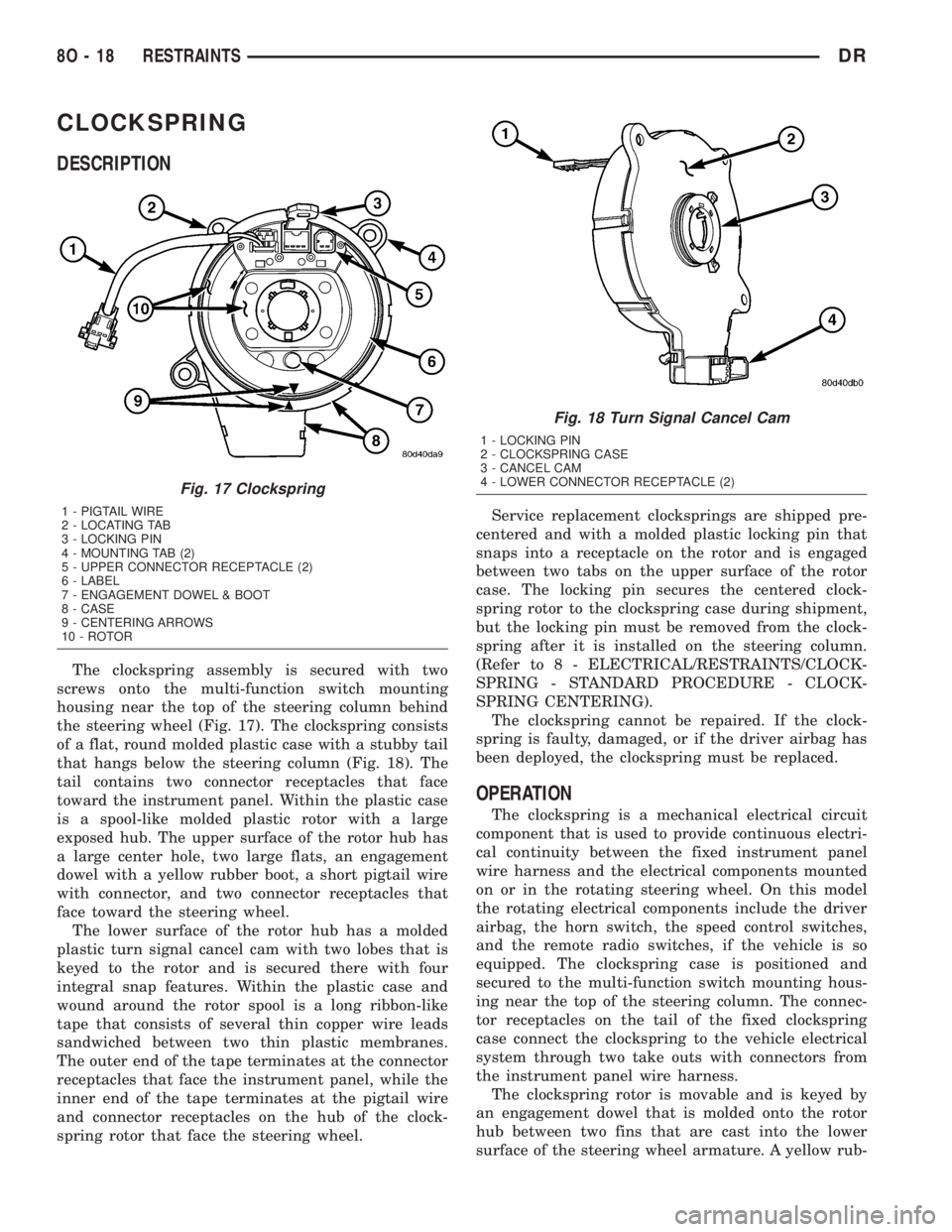
CLOCKSPRING
DESCRIPTION
The clockspring assembly is secured with two
screws onto the multi-function switch mounting
housing near the top of the steering column behind
the steering wheel (Fig. 17). The clockspring consists
of a flat, round molded plastic case with a stubby tail
that hangs below the steering column (Fig. 18). The
tail contains two connector receptacles that face
toward the instrument panel. Within the plastic case
is a spool-like molded plastic rotor with a large
exposed hub. The upper surface of the rotor hub has
a large center hole, two large flats, an engagement
dowel with a yellow rubber boot, a short pigtail wire
with connector, and two connector receptacles that
face toward the steering wheel.
The lower surface of the rotor hub has a molded
plastic turn signal cancel cam with two lobes that is
keyed to the rotor and is secured there with four
integral snap features. Within the plastic case and
wound around the rotor spool is a long ribbon-like
tape that consists of several thin copper wire leads
sandwiched between two thin plastic membranes.
The outer end of the tape terminates at the connector
receptacles that face the instrument panel, while the
inner end of the tape terminates at the pigtail wire
and connector receptacles on the hub of the clock-
spring rotor that face the steering wheel.Service replacement clocksprings are shipped pre-
centered and with a molded plastic locking pin that
snaps into a receptacle on the rotor and is engaged
between two tabs on the upper surface of the rotor
case. The locking pin secures the centered clock-
spring rotor to the clockspring case during shipment,
but the locking pin must be removed from the clock-
spring after it is installed on the steering column.
(Refer to 8 - ELECTRICAL/RESTRAINTS/CLOCK-
SPRING - STANDARD PROCEDURE - CLOCK-
SPRING CENTERING).
The clockspring cannot be repaired. If the clock-
spring is faulty, damaged, or if the driver airbag has
been deployed, the clockspring must be replaced.
OPERATION
The clockspring is a mechanical electrical circuit
component that is used to provide continuous electri-
cal continuity between the fixed instrument panel
wire harness and the electrical components mounted
on or in the rotating steering wheel. On this model
the rotating electrical components include the driver
airbag, the horn switch, the speed control switches,
and the remote radio switches, if the vehicle is so
equipped. The clockspring case is positioned and
secured to the multi-function switch mounting hous-
ing near the top of the steering column. The connec-
tor receptacles on the tail of the fixed clockspring
case connect the clockspring to the vehicle electrical
system through two take outs with connectors from
the instrument panel wire harness.
The clockspring rotor is movable and is keyed by
an engagement dowel that is molded onto the rotor
hub between two fins that are cast into the lower
surface of the steering wheel armature. A yellow rub-
Fig. 17 Clockspring
1 - PIGTAIL WIRE
2 - LOCATING TAB
3 - LOCKING PIN
4 - MOUNTING TAB (2)
5 - UPPER CONNECTOR RECEPTACLE (2)
6 - LABEL
7 - ENGAGEMENT DOWEL & BOOT
8 - CASE
9 - CENTERING ARROWS
10 - ROTOR
Fig. 18 Turn Signal Cancel Cam
1 - LOCKING PIN
2 - CLOCKSPRING CASE
3 - CANCEL CAM
4 - LOWER CONNECTOR RECEPTACLE (2)
8O - 18 RESTRAINTSDR
Page 620 of 2895
ber boot is installed over the engagement dowel to
eliminate contact noise between the dowel and the
steering wheel. The two lobes on the turn signal can-
cel cam on the lower surface of the clockspring rotor
hub contact a turn signal cancel actuator of the
multi-function switch to provide automatic turn sig-
nal cancellation. The yellow sleeved pigtail wires on
the upper surface of the clockspring rotor connect the
clockspring to the driver airbag, while a steering
wheel wire harness connects the two connector recep-
tacles on the upper surface of the clockspring rotor to
the horn switch feed pigtail wire connector and, if
the vehicle is so equipped, to the optional speed con-
trol and remote radio switches on the steering wheel.
Like the clockspring in a timepiece, the clockspring
tape has travel limits and can be damaged by being
wound too tightly during full stop-to-stop steering
wheel rotation. To prevent this from occurring, the
clockspring is centered when it is installed on the
steering column. Centering the clockspring indexes
the clockspring tape to the movable steering compo-
nents so that the tape can operate within its
designed travel limits. However, if the clockspring is
removed from the steering column or if the steering
shaft is disconnected from the steering gear, the
clockspring spool can change position relative to the
movable steering components. The clockspring must
be re-centered following completion of this service or
the tape may be damaged.
Service replacement clocksprings are shipped pre-
centered and with a plastic locking pin installed.
This locking pin should not be disengaged until the
clockspring has been installed on the steering col-
umn. If the locking pin is removed or damaged before
the clockspring is installed on a steering column, the
clockspring centering procedure must be performed.
(Refer to 8 - ELECTRICAL/RESTRAINTS/CLOCK-
SPRING - STANDARD PROCEDURE - CLOCK-
SPRING CENTERING).
STANDARD PROCEDURE - CLOCKSPRING
CENTERING
The clockspring is designed to wind and unwind
when the steering wheel is rotated, but is only
designed to rotate the same number of turns (about
five complete rotations) as the steering wheel can be
turned from stop to stop. Centering the clockspring
indexes the clockspring tape to other steering compo-
nents so that it can operate within its designed
travel limits. The rotor of a centered clockspring can
be rotated two and one-half turns in either direction
from the centered position, without damaging the
clockspring tape.
However, if the clockspring is removed for service
or if the steering column is disconnected from the
steering gear, the clockspring tape can change posi-tion relative to the other steering components. The
clockspring must then be re-centered following com-
pletion of such service or the clockspring tape may be
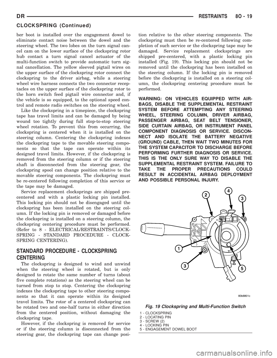
damaged. Service replacement clocksprings are
shipped pre-centered, with a plastic locking pin
installed (Fig. 19). This locking pin should not be
removed until the clockspring has been installed on
the steering column. If the locking pin is removed
before the clockspring is installed on a steering col-
umn, the clockspring centering procedure must be
performed.
WARNING: ON VEHICLES EQUIPPED WITH AIR-
BAGS, DISABLE THE SUPPLEMENTAL RESTRAINT
SYSTEM BEFORE ATTEMPTING ANY STEERING
WHEEL, STEERING COLUMN, DRIVER AIRBAG,
PASSENGER AIRBAG, SEAT BELT TENSIONER,
SIDE CURTAIN AIRBAG, OR INSTRUMENT PANEL
COMPONENT DIAGNOSIS OR SERVICE. DISCON-
NECT AND ISOLATE THE BATTERY NEGATIVE
(GROUND) CABLE, THEN WAIT TWO MINUTES FOR
THE SYSTEM CAPACITOR TO DISCHARGE BEFORE
PERFORMING FURTHER DIAGNOSIS OR SERVICE.
THIS IS THE ONLY SURE WAY TO DISABLE THE
SUPPLEMENTAL RESTRAINT SYSTEM. FAILURE TO
TAKE THE PROPER PRECAUTIONS COULD
RESULT IN ACCIDENTAL AIRBAG DEPLOYMENT
AND POSSIBLE PERSONAL INJURY.
Fig. 19 Clockspring and Multi-Function Switch
1 - CLOCKSPRING
2 - LOCATING PIN
3 - SCREW (2)
4 - LOCKING PIN
5 - ENGAGEMENT DOWEL BOOT
DRRESTRAINTS 8O - 19
CLOCKSPRING (Continued)