DODGE RAM 2003 Service Repair Manual
Manufacturer: DODGE, Model Year: 2003, Model line: RAM, Model: DODGE RAM 2003Pages: 2895, PDF Size: 83.15 MB
Page 641 of 2895
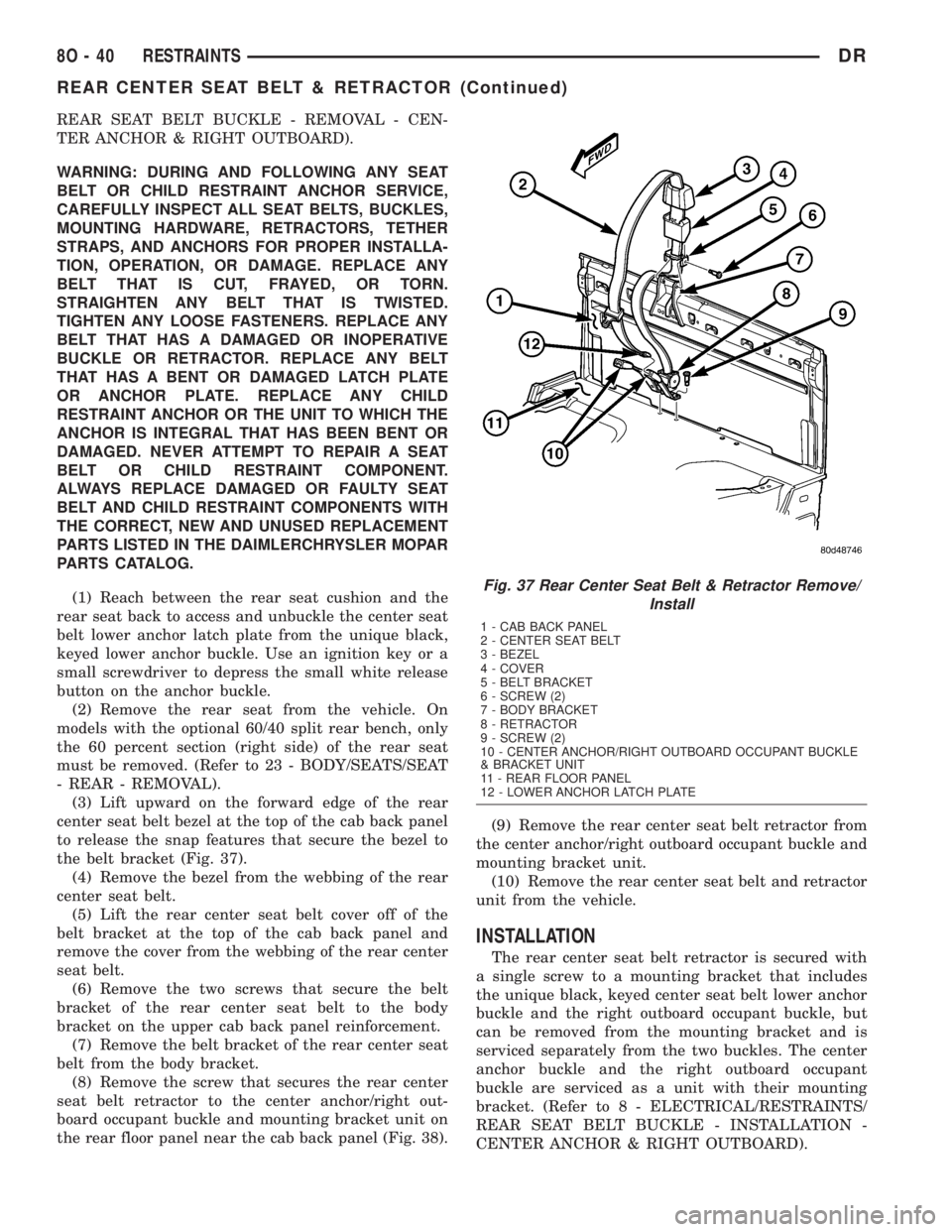
REAR SEAT BELT BUCKLE - REMOVAL - CEN-
TER ANCHOR & RIGHT OUTBOARD).
WARNING: DURING AND FOLLOWING ANY SEAT
BELT OR CHILD RESTRAINT ANCHOR SERVICE,
CAREFULLY INSPECT ALL SEAT BELTS, BUCKLES,
MOUNTING HARDWARE, RETRACTORS, TETHER
STRAPS, AND ANCHORS FOR PROPER INSTALLA-
TION, OPERATION, OR DAMAGE. REPLACE ANY
BELT THAT IS CUT, FRAYED, OR TORN.
STRAIGHTEN ANY BELT THAT IS TWISTED.
TIGHTEN ANY LOOSE FASTENERS. REPLACE ANY
BELT THAT HAS A DAMAGED OR INOPERATIVE
BUCKLE OR RETRACTOR. REPLACE ANY BELT
THAT HAS A BENT OR DAMAGED LATCH PLATE
OR ANCHOR PLATE. REPLACE ANY CHILD
RESTRAINT ANCHOR OR THE UNIT TO WHICH THE
ANCHOR IS INTEGRAL THAT HAS BEEN BENT OR
DAMAGED. NEVER ATTEMPT TO REPAIR A SEAT
BELT OR CHILD RESTRAINT COMPONENT.
ALWAYS REPLACE DAMAGED OR FAULTY SEAT
BELT AND CHILD RESTRAINT COMPONENTS WITH
THE CORRECT, NEW AND UNUSED REPLACEMENT
PARTS LISTED IN THE DAIMLERCHRYSLER MOPAR
PARTS CATALOG.
(1) Reach between the rear seat cushion and the
rear seat back to access and unbuckle the center seat
belt lower anchor latch plate from the unique black,
keyed lower anchor buckle. Use an ignition key or a
small screwdriver to depress the small white release
button on the anchor buckle.
(2) Remove the rear seat from the vehicle. On
models with the optional 60/40 split rear bench, only
the 60 percent section (right side) of the rear seat
must be removed. (Refer to 23 - BODY/SEATS/SEAT
- REAR - REMOVAL).
(3) Lift upward on the forward edge of the rear
center seat belt bezel at the top of the cab back panel
to release the snap features that secure the bezel to
the belt bracket (Fig. 37).
(4) Remove the bezel from the webbing of the rear
center seat belt.
(5) Lift the rear center seat belt cover off of the
belt bracket at the top of the cab back panel and
remove the cover from the webbing of the rear center
seat belt.
(6) Remove the two screws that secure the belt
bracket of the rear center seat belt to the body
bracket on the upper cab back panel reinforcement.
(7) Remove the belt bracket of the rear center seat
belt from the body bracket.
(8) Remove the screw that secures the rear center
seat belt retractor to the center anchor/right out-
board occupant buckle and mounting bracket unit on
the rear floor panel near the cab back panel (Fig. 38).(9) Remove the rear center seat belt retractor from
the center anchor/right outboard occupant buckle and
mounting bracket unit.
(10) Remove the rear center seat belt and retractor
unit from the vehicle.
INSTALLATION
The rear center seat belt retractor is secured with
a single screw to a mounting bracket that includes
the unique black, keyed center seat belt lower anchor
buckle and the right outboard occupant buckle, but
can be removed from the mounting bracket and is
serviced separately from the two buckles. The center
anchor buckle and the right outboard occupant
buckle are serviced as a unit with their mounting
bracket. (Refer to 8 - ELECTRICAL/RESTRAINTS/
REAR SEAT BELT BUCKLE - INSTALLATION -
CENTER ANCHOR & RIGHT OUTBOARD).
Fig. 37 Rear Center Seat Belt & Retractor Remove/
Install
1 - CAB BACK PANEL
2 - CENTER SEAT BELT
3 - BEZEL
4 - COVER
5 - BELT BRACKET
6 - SCREW (2)
7 - BODY BRACKET
8 - RETRACTOR
9 - SCREW (2)
10 - CENTER ANCHOR/RIGHT OUTBOARD OCCUPANT BUCKLE
& BRACKET UNIT
11 - REAR FLOOR PANEL
12 - LOWER ANCHOR LATCH PLATE
8O - 40 RESTRAINTSDR
REAR CENTER SEAT BELT & RETRACTOR (Continued)
Page 642 of 2895
WARNING: DURING AND FOLLOWING ANY SEAT
BELT OR CHILD RESTRAINT ANCHOR SERVICE,
CAREFULLY INSPECT ALL SEAT BELTS, BUCKLES,
MOUNTING HARDWARE, RETRACTORS, TETHER
STRAPS, AND ANCHORS FOR PROPER INSTALLA-
TION, OPERATION, OR DAMAGE. REPLACE ANY
BELT THAT IS CUT, FRAYED, OR TORN.
STRAIGHTEN ANY BELT THAT IS TWISTED.
TIGHTEN ANY LOOSE FASTENERS. REPLACE ANY
BELT THAT HAS A DAMAGED OR INOPERATIVE
BUCKLE OR RETRACTOR. REPLACE ANY BELT
THAT HAS A BENT OR DAMAGED LATCH PLATE
OR ANCHOR PLATE. REPLACE ANY CHILD
RESTRAINT ANCHOR OR THE UNIT TO WHICH THE
ANCHOR IS INTEGRAL THAT HAS BEEN BENT OR
DAMAGED. NEVER ATTEMPT TO REPAIR A SEAT
BELT OR CHILD RESTRAINT COMPONENT.
ALWAYS REPLACE DAMAGED OR FAULTY SEAT
BELT AND CHILD RESTRAINT COMPONENTS WITH
THE CORRECT, NEW AND UNUSED REPLACEMENT
PARTS LISTED IN THE DAIMLERCHRYSLER MOPAR
PARTS CATALOG.(1) Position the rear center seat belt and retractor
unit onto the center anchor/right outboard occupant
buckle and mounting bracket unit on the rear floor
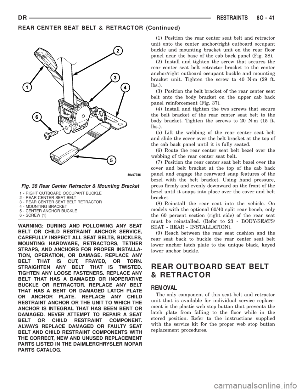
panel near the base of the cab back panel (Fig. 38).
(2) Install and tighten the screw that secures the
rear center seat belt retractor bracket to the center
anchor/right outboard occupant buckle and mounting
bracket unit. Tighten the screw to 40 N´m (29 ft.
lbs.).
(3) Position the belt bracket of the rear center seat
belt onto the body bracket on the upper cab back
panel reinforcement (Fig. 37).
(4) Install and tighten the two screws that secure
the belt bracket of the rear center seat belt to the
body bracket. Tighten the screws to 20 N´m (15 ft.
lbs.).
(5) Lift the webbing of the rear center seat belt
and slide the cover over the belt bracket at the top of
the cab back panel until it is fully seated.
(6) Route the rear center seat belt bezel over the
webbing of the rear center seat belt.
(7) Position the rear center seat belt bezel over the
cover and belt bracket at the top of the cab back
panel and engage the rearward snap features of the
bezel with the belt bracket. Using hand pressure,
press firmly and evenly downward on the front of the
bezel until it snaps into place over the cover and belt
bracket.
(8) Reinstall the rear seat into the vehicle. On
models with the optional 60/40 split rear bench, only
the 60 percent section (right side) of the rear seat
must be reinstalled. (Refer to 23 - BODY/SEATS/
SEAT - REAR - INSTALLATION).
(9) Reach between the rear seat cushion and the
rear seat back to buckle the rear center seat belt
lower anchor latch plate to the unique black, keyed
lower anchor buckle.
REAR OUTBOARD SEAT BELT
& RETRACTOR
REMOVAL
The only component of this seat belt and retractor
unit that is available for individual service replace-
ment is the plastic web stop button that prevents the
latch plate from falling to the floor while in the
stored position. Refer to the instructions supplied
with the service kit for the proper web stop button
replacement procedures.
Fig. 38 Rear Center Retractor & Mounting Bracket
1 - RIGHT OUTBOARD OCCUPANT BUCKLE
2 - REAR CENTER SEAT BELT
3 - REAR CENTER SEAT BELT RETRACTOR
4 - MOUNTING BRACKET
5 - CENTER ANCHOR BUCKLE
6 - SCREW (1)
DRRESTRAINTS 8O - 41
REAR CENTER SEAT BELT & RETRACTOR (Continued)
Page 643 of 2895
WARNING: DURING AND FOLLOWING ANY SEAT
BELT OR CHILD RESTRAINT ANCHOR SERVICE,
CAREFULLY INSPECT ALL SEAT BELTS, BUCKLES,
MOUNTING HARDWARE, RETRACTORS, TETHER
STRAPS, AND ANCHORS FOR PROPER INSTALLA-
TION, OPERATION, OR DAMAGE. REPLACE ANY
BELT THAT IS CUT, FRAYED, OR TORN.
STRAIGHTEN ANY BELT THAT IS TWISTED.
TIGHTEN ANY LOOSE FASTENERS. REPLACE ANY
BELT THAT HAS A DAMAGED OR INOPERATIVE
BUCKLE OR RETRACTOR. REPLACE ANY BELT
THAT HAS A BENT OR DAMAGED LATCH PLATE
OR ANCHOR PLATE. REPLACE ANY CHILD
RESTRAINT ANCHOR OR THE UNIT TO WHICH THE
ANCHOR IS INTEGRAL THAT HAS BEEN BENT OR
DAMAGED. NEVER ATTEMPT TO REPAIR A SEAT
BELT OR CHILD RESTRAINT COMPONENT.
ALWAYS REPLACE DAMAGED OR FAULTY SEAT
BELT AND CHILD RESTRAINT COMPONENTS WITH
THE CORRECT, NEW AND UNUSED REPLACEMENT
PARTS LISTED IN THE DAIMLERCHRYSLER MOPAR
PARTS CATALOG.
(1) Remove the rear seat from the vehicle. (Refer
to 23 - BODY/SEATS/SEAT - REAR - REMOVAL).
(2) Remove the screw that secures the lower seat
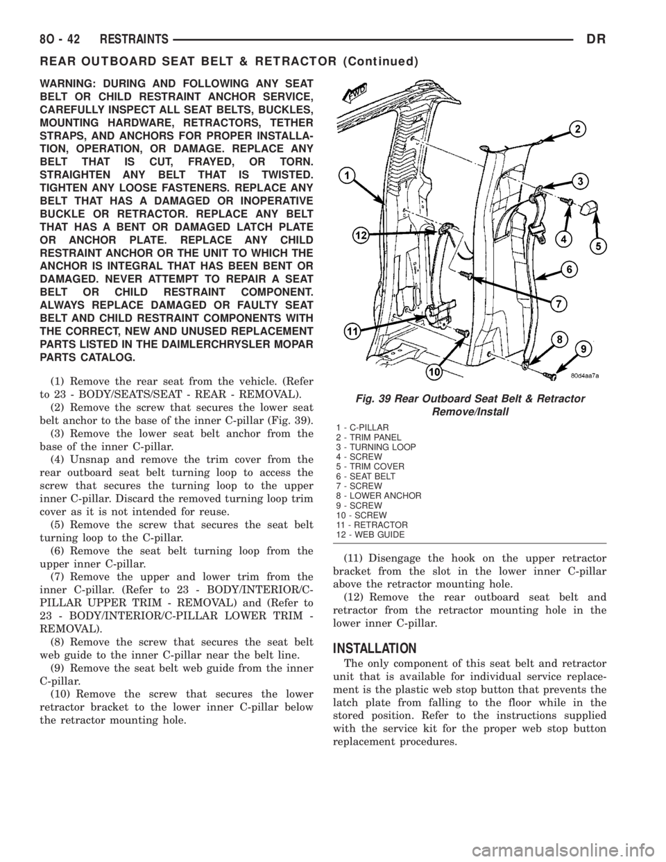
belt anchor to the base of the inner C-pillar (Fig. 39).
(3) Remove the lower seat belt anchor from the
base of the inner C-pillar.
(4) Unsnap and remove the trim cover from the
rear outboard seat belt turning loop to access the
screw that secures the turning loop to the upper
inner C-pillar. Discard the removed turning loop trim
cover as it is not intended for reuse.
(5) Remove the screw that secures the seat belt
turning loop to the C-pillar.
(6) Remove the seat belt turning loop from the
upper inner C-pillar.
(7) Remove the upper and lower trim from the
inner C-pillar. (Refer to 23 - BODY/INTERIOR/C-
PILLAR UPPER TRIM - REMOVAL) and (Refer to
23 - BODY/INTERIOR/C-PILLAR LOWER TRIM -
REMOVAL).
(8) Remove the screw that secures the seat belt
web guide to the inner C-pillar near the belt line.
(9) Remove the seat belt web guide from the inner
C-pillar.
(10) Remove the screw that secures the lower
retractor bracket to the lower inner C-pillar below
the retractor mounting hole.(11) Disengage the hook on the upper retractor
bracket from the slot in the lower inner C-pillar
above the retractor mounting hole.
(12) Remove the rear outboard seat belt and
retractor from the retractor mounting hole in the
lower inner C-pillar.
INSTALLATION
The only component of this seat belt and retractor
unit that is available for individual service replace-
ment is the plastic web stop button that prevents the
latch plate from falling to the floor while in the
stored position. Refer to the instructions supplied
with the service kit for the proper web stop button
replacement procedures.
Fig. 39 Rear Outboard Seat Belt & Retractor
Remove/Install
1 - C-PILLAR
2 - TRIM PANEL
3 - TURNING LOOP
4 - SCREW
5 - TRIM COVER
6 - SEAT BELT
7 - SCREW
8 - LOWER ANCHOR
9 - SCREW
10 - SCREW
11 - RETRACTOR
12 - WEB GUIDE
8O - 42 RESTRAINTSDR
REAR OUTBOARD SEAT BELT & RETRACTOR (Continued)
Page 644 of 2895
WARNING: DURING AND FOLLOWING ANY SEAT
BELT OR CHILD RESTRAINT ANCHOR SERVICE,
CAREFULLY INSPECT ALL SEAT BELTS, BUCKLES,
MOUNTING HARDWARE, RETRACTORS, TETHER
STRAPS, AND ANCHORS FOR PROPER INSTALLA-
TION, OPERATION, OR DAMAGE. REPLACE ANY
BELT THAT IS CUT, FRAYED, OR TORN.
STRAIGHTEN ANY BELT THAT IS TWISTED.
TIGHTEN ANY LOOSE FASTENERS. REPLACE ANY
BELT THAT HAS A DAMAGED OR INOPERATIVE
BUCKLE OR RETRACTOR. REPLACE ANY BELT
THAT HAS A BENT OR DAMAGED LATCH PLATE
OR ANCHOR PLATE. REPLACE ANY CHILD
RESTRAINT ANCHOR OR THE UNIT TO WHICH THE
ANCHOR IS INTEGRAL THAT HAS BEEN BENT OR
DAMAGED. NEVER ATTEMPT TO REPAIR A SEAT
BELT OR CHILD RESTRAINT COMPONENT.
ALWAYS REPLACE DAMAGED OR FAULTY SEAT
BELT AND CHILD RESTRAINT COMPONENTS WITH
THE CORRECT, NEW AND UNUSED REPLACEMENT
PARTS LISTED IN THE DAIMLERCHRYSLER MOPAR
PARTS CATALOG.
(1) Position the rear outboard seat belt and retrac-
tor to the retractor mounting hole in the lower inner
C-pillar (Fig. 39).
(2) Engage the hook on the upper retractor bracket
into the slot in the lower inner C-pillar above the
retractor mounting hole.
(3) Install and tighten the screw that secures the
lower retractor bracket to the lower inner C-pillar
below the retractor mounting hole. Tighten the screw
to 40 N´m (29 ft. lbs.).
(4) Position the seat belt web guide to the inner
C-pillar near the belt line.
(5) Install and tighten the screw that secures the
seat belt web guide to the inner C-pillar. Tighten the
screw to 2 N´m (20 in. lbs.).
(6) Reinstall the upper and lower trim onto the
inner C-pillar. (Refer to 23 - BODY/INTERIOR/C-
PILLAR UPPER TRIM - INSTALLATION) and
(Refer to 23 - BODY/INTERIOR/C-PILLAR LOWER
TRIM - INSTALLATION).
(7) Position the seat belt turning loop onto the
upper inner C-pillar.
(8) Install and tighten the screw that secures the
seat belt turning loop to the C-pillar. Tighten the
screw to 40 N´m (29 ft. lbs.).
(9) Engage the lower snap features of the new trim
cover over the rear outboard seat belt turning loop
and, using hand pressure, press firmly and evenly on
the top of the trim cover until it snaps into place.
(10) Position the lower seat belt anchor to the base
of the inner C-pillar.
(11) Install and tighten the screw that secures the
lower seat belt anchor to the base of the inner C-pil-
lar. Tighten the screw to 40 N´m (29 ft. lbs.).(12) Reinstall the rear seat into the vehicle. (Refer
to 23 - BODY/SEATS/SEAT - REAR - INSTALLA-
TION).
REAR SEAT BELT BUCKLE
REMOVAL
REMOVAL - CENTER & LEFT OUTBOARD
WARNING: DURING AND FOLLOWING ANY SEAT
BELT OR CHILD RESTRAINT ANCHOR SERVICE,
CAREFULLY INSPECT ALL SEAT BELTS, BUCKLES,
MOUNTING HARDWARE, RETRACTORS, TETHER
STRAPS, AND ANCHORS FOR PROPER INSTALLA-
TION, OPERATION, OR DAMAGE. REPLACE ANY
BELT THAT IS CUT, FRAYED, OR TORN.
STRAIGHTEN ANY BELT THAT IS TWISTED.
TIGHTEN ANY LOOSE FASTENERS. REPLACE ANY
BELT THAT HAS A DAMAGED OR INOPERATIVE
BUCKLE OR RETRACTOR. REPLACE ANY BELT
THAT HAS A BENT OR DAMAGED LATCH PLATE
OR ANCHOR PLATE. REPLACE ANY CHILD
RESTRAINT ANCHOR OR THE UNIT TO WHICH THE
ANCHOR IS INTEGRAL THAT HAS BEEN BENT OR
DAMAGED. NEVER ATTEMPT TO REPAIR A SEAT
BELT OR CHILD RESTRAINT COMPONENT.
ALWAYS REPLACE DAMAGED OR FAULTY SEAT
BELT AND CHILD RESTRAINT COMPONENTS WITH
THE CORRECT, NEW AND UNUSED REPLACEMENT
PARTS LISTED IN THE DAIMLERCHRYSLER MOPAR
PARTS CATALOG.
(1) Lift up the rear seat cushion into its stowed
position against the rear seat back.
(2) Remove the screw that secures either the cen-
ter or the left outboard occupant buckle unit to the
rear floor panel near the base of the cab back panel
(Fig. 40). On models with the optional 60/40 split
rear bench, the screw that secures the buckle unit
also secures one of the rear seat mounting brackets
to the rear floor panel.
(3) Remove the center or the left outboard occu-
pant buckle unit from the rear floor panel or from
the rear seat mounting bracket.
REMOVAL - CENTER ANCHOR & RIGHT
OUTBOARD
The unique black, keyed center seat belt lower
anchor buckle and the right outboard occupant
buckle are serviced as a unit with their mounting
bracket. The rear center seat belt retractor is also
secured to the mounting bracket with these two
buckles, but can be removed from the mounting
bracket and is serviced separately from the two buck-
DRRESTRAINTS 8O - 43
REAR OUTBOARD SEAT BELT & RETRACTOR (Continued)
Page 645 of 2895
les. (Refer to 8 - ELECTRICAL/RESTRAINTS/REAR
CENTER SEAT BELT & RETRACTOR - REMOVAL).
WARNING: DURING AND FOLLOWING ANY SEAT
BELT OR CHILD RESTRAINT ANCHOR SERVICE,
CAREFULLY INSPECT ALL SEAT BELTS, BUCKLES,
MOUNTING HARDWARE, RETRACTORS, TETHER
STRAPS, AND ANCHORS FOR PROPER INSTALLA-
TION, OPERATION, OR DAMAGE. REPLACE ANY
BELT THAT IS CUT, FRAYED, OR TORN.
STRAIGHTEN ANY BELT THAT IS TWISTED.
TIGHTEN ANY LOOSE FASTENERS. REPLACE ANY
BELT THAT HAS A DAMAGED OR INOPERATIVE
BUCKLE OR RETRACTOR. REPLACE ANY BELT
THAT HAS A BENT OR DAMAGED LATCH PLATE
OR ANCHOR PLATE. REPLACE ANY CHILD
RESTRAINT ANCHOR OR THE UNIT TO WHICH THE
ANCHOR IS INTEGRAL THAT HAS BEEN BENT OR
DAMAGED. NEVER ATTEMPT TO REPAIR A SEAT
BELT OR CHILD RESTRAINT COMPONENT.
ALWAYS REPLACE DAMAGED OR FAULTY SEAT
BELT AND CHILD RESTRAINT COMPONENTS WITH
THE CORRECT, NEW AND UNUSED REPLACEMENTPARTS LISTED IN THE DAIMLERCHRYSLER MOPAR
PARTS CATALOG.
(1) Reach between the rear seat cushion and the
rear seat back to access and unbuckle the rear center
seat belt lower anchor latch plate from the unique
black, keyed lower anchor buckle. Use an ignition
key or a small screwdriver to depress the small white
release button on the anchor buckle.
(2) Remove the rear seat from the vehicle. On
models with the optional 60/40 split rear bench, only
the 60 percent section (right side) of the rear seat
must be removed. (Refer to 23 - BODY/SEATS/SEAT
- REAR - REMOVAL).
(3) Remove the screw that secures the rear center
seat belt retractor to the center anchor/right out-
board occupant buckle and mounting bracket unit on
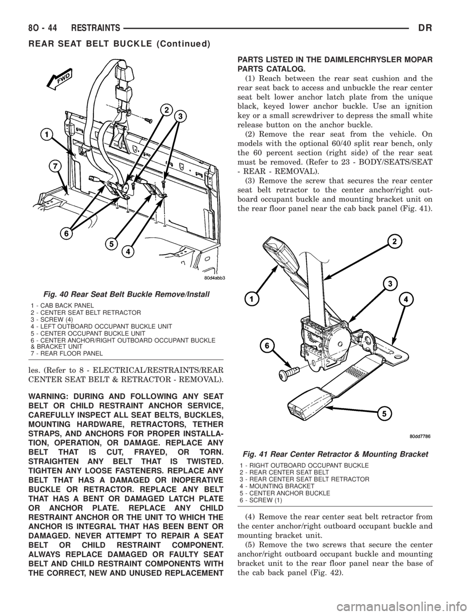
the rear floor panel near the cab back panel (Fig. 41).
(4) Remove the rear center seat belt retractor from
the center anchor/right outboard occupant buckle and
mounting bracket unit.
(5) Remove the two screws that secure the center
anchor/right outboard occupant buckle and mounting
bracket unit to the rear floor panel near the base of
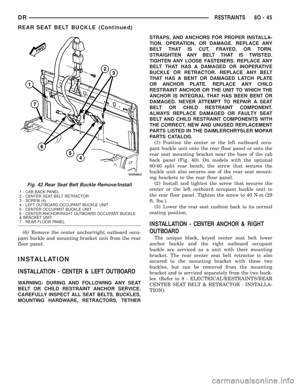
the cab back panel (Fig. 42).
Fig. 40 Rear Seat Belt Buckle Remove/Install
1 - CAB BACK PANEL
2 - CENTER SEAT BELT RETRACTOR
3 - SCREW (4)
4 - LEFT OUTBOARD OCCUPANT BUCKLE UNIT
5 - CENTER OCCUPANT BUCKLE UNIT
6 - CENTER ANCHOR/RIGHT OUTBOARD OCCUPANT BUCKLE
& BRACKET UNIT
7 - REAR FLOOR PANEL
Fig. 41 Rear Center Retractor & Mounting Bracket
1 - RIGHT OUTBOARD OCCUPANT BUCKLE
2 - REAR CENTER SEAT BELT
3 - REAR CENTER SEAT BELT RETRACTOR
4 - MOUNTING BRACKET
5 - CENTER ANCHOR BUCKLE
6 - SCREW (1)
8O - 44 RESTRAINTSDR
REAR SEAT BELT BUCKLE (Continued)
Page 646 of 2895
(6) Remove the center anchor/right outboard occu-
pant buckle and mounting bracket unit from the rear
floor panel.
INSTALLATION
INSTALLATION - CENTER & LEFT OUTBOARD
WARNING: DURING AND FOLLOWING ANY SEAT
BELT OR CHILD RESTRAINT ANCHOR SERVICE,
CAREFULLY INSPECT ALL SEAT BELTS, BUCKLES,
MOUNTING HARDWARE, RETRACTORS, TETHERSTRAPS, AND ANCHORS FOR PROPER INSTALLA-
TION, OPERATION, OR DAMAGE. REPLACE ANY
BELT THAT IS CUT, FRAYED, OR TORN.
STRAIGHTEN ANY BELT THAT IS TWISTED.
TIGHTEN ANY LOOSE FASTENERS. REPLACE ANY
BELT THAT HAS A DAMAGED OR INOPERATIVE
BUCKLE OR RETRACTOR. REPLACE ANY BELT
THAT HAS A BENT OR DAMAGED LATCH PLATE
OR ANCHOR PLATE. REPLACE ANY CHILD
RESTRAINT ANCHOR OR THE UNIT TO WHICH THE
ANCHOR IS INTEGRAL THAT HAS BEEN BENT OR
DAMAGED. NEVER ATTEMPT TO REPAIR A SEAT
BELT OR CHILD RESTRAINT COMPONENT.
ALWAYS REPLACE DAMAGED OR FAULTY SEAT
BELT AND CHILD RESTRAINT COMPONENTS WITH
THE CORRECT, NEW AND UNUSED REPLACEMENT
PARTS LISTED IN THE DAIMLERCHRYSLER MOPAR
PARTS CATALOG.
(1) Position the center or the left outboard occu-
pant buckle unit onto the rear floor panel or onto the
rear seat mounting bracket near the base of the cab
back panel (Fig. 40). On models with the optional
60/40 split rear bench, the screw that secures the
buckle unit also secures one of the rear seat mount-
ing brackets to the rear floor panel.
(2) Install and tighten the screw that secures the
center or the left outboard occupant buckle unit to
the rear floor panel. Tighten the screw to 40 N´m (29
ft. lbs.).
(3) Lower the rear seat cushion back to its normal
seating position.
INSTALLATION - CENTER ANCHOR & RIGHT
OUTBOARD
The unique black, keyed center seat belt lower
anchor buckle and the right outboard occupant
buckle are serviced as a unit with their mounting
bracket. The rear center seat belt retractor is also
secured to the mounting bracket with these two
buckles, but can be removed from the mounting
bracket and is serviced separately from the two buck-
les. (Refer to 8 - ELECTRICAL/RESTRAINTS/REAR
CENTER SEAT BELT & RETRACTOR - INSTALLA-
TION).
Fig. 42 Rear Seat Belt Buckle Remove/Install
1 - CAB BACK PANEL
2 - CENTER SEAT BELT RETRACTOR
3 - SCREW (4)
4 - LEFT OUTBOARD OCCUPANT BUCKLE UNIT
5 - CENTER OCCUPANT BUCKLE UNIT
6 - CENTER ANCHOR/RIGHT OUTBOARD OCCUPANT BUCKLE
& BRACKET UNIT
7 - REAR FLOOR PANEL
DRRESTRAINTS 8O - 45
REAR SEAT BELT BUCKLE (Continued)
Page 647 of 2895
WARNING: DURING AND FOLLOWING ANY SEAT
BELT OR CHILD RESTRAINT ANCHOR SERVICE,
CAREFULLY INSPECT ALL SEAT BELTS, BUCKLES,
MOUNTING HARDWARE, RETRACTORS, TETHER
STRAPS, AND ANCHORS FOR PROPER INSTALLA-
TION, OPERATION, OR DAMAGE. REPLACE ANY
BELT THAT IS CUT, FRAYED, OR TORN.
STRAIGHTEN ANY BELT THAT IS TWISTED.
TIGHTEN ANY LOOSE FASTENERS. REPLACE ANY
BELT THAT HAS A DAMAGED OR INOPERATIVE
BUCKLE OR RETRACTOR. REPLACE ANY BELT
THAT HAS A BENT OR DAMAGED LATCH PLATE
OR ANCHOR PLATE. REPLACE ANY CHILD
RESTRAINT ANCHOR OR THE UNIT TO WHICH THE
ANCHOR IS INTEGRAL THAT HAS BEEN BENT OR
DAMAGED. NEVER ATTEMPT TO REPAIR A SEAT
BELT OR CHILD RESTRAINT COMPONENT.
ALWAYS REPLACE DAMAGED OR FAULTY SEAT
BELT AND CHILD RESTRAINT COMPONENTS WITH
THE CORRECT, NEW AND UNUSED REPLACEMENT
PARTS LISTED IN THE DAIMLERCHRYSLER MOPAR
PARTS CATALOG.
(1) Position the center anchor/right outboard occu-
pant buckle and mounting bracket unit onto the rear
floor panel near the base of the cab back panel (Fig.
42).
(2) Install and tighten the two screws that secure
the center anchor/right outboard occupant buckle and
mounting bracket unit to the rear floor panel.
Tighten the screws to 40 N´m (29 ft. lbs.).
(3) Position the rear center seat belt retractor onto
the center anchor/right outboard occupant buckle and
mounting bracket unit (Fig. 41).
(4)
Install and tighten the screw that secures the
rear center seat belt retractor to the center anchor/
right outboard occupant buckle and mounting bracket
unit. Tighten the screw to 40 N´m (29 ft. lbs.).
(5) Reinstall the rear seat into the vehicle. On
models with the optional 60/40 split rear bench, only
the 60 percent section (right side) of the rear seat
must be reinstalled. (Refer to 23 - BODY/SEATS/
SEAT - REAR - INSTALLATION).
(6) Reach between the rear seat cushion and the
rear seat back to access and buckle the rear center
seat belt lower anchor latch plate to the unique
black, keyed lower anchor buckle.
SEAT BELT SWITCH
DESCRIPTION
The seat belt switch is a small, normally open, sin-
gle pole, single throw, leaf contact, momentary
switch. Only one seat belt switch is installed in the
vehicle, and it is integral to the buckle of the driver
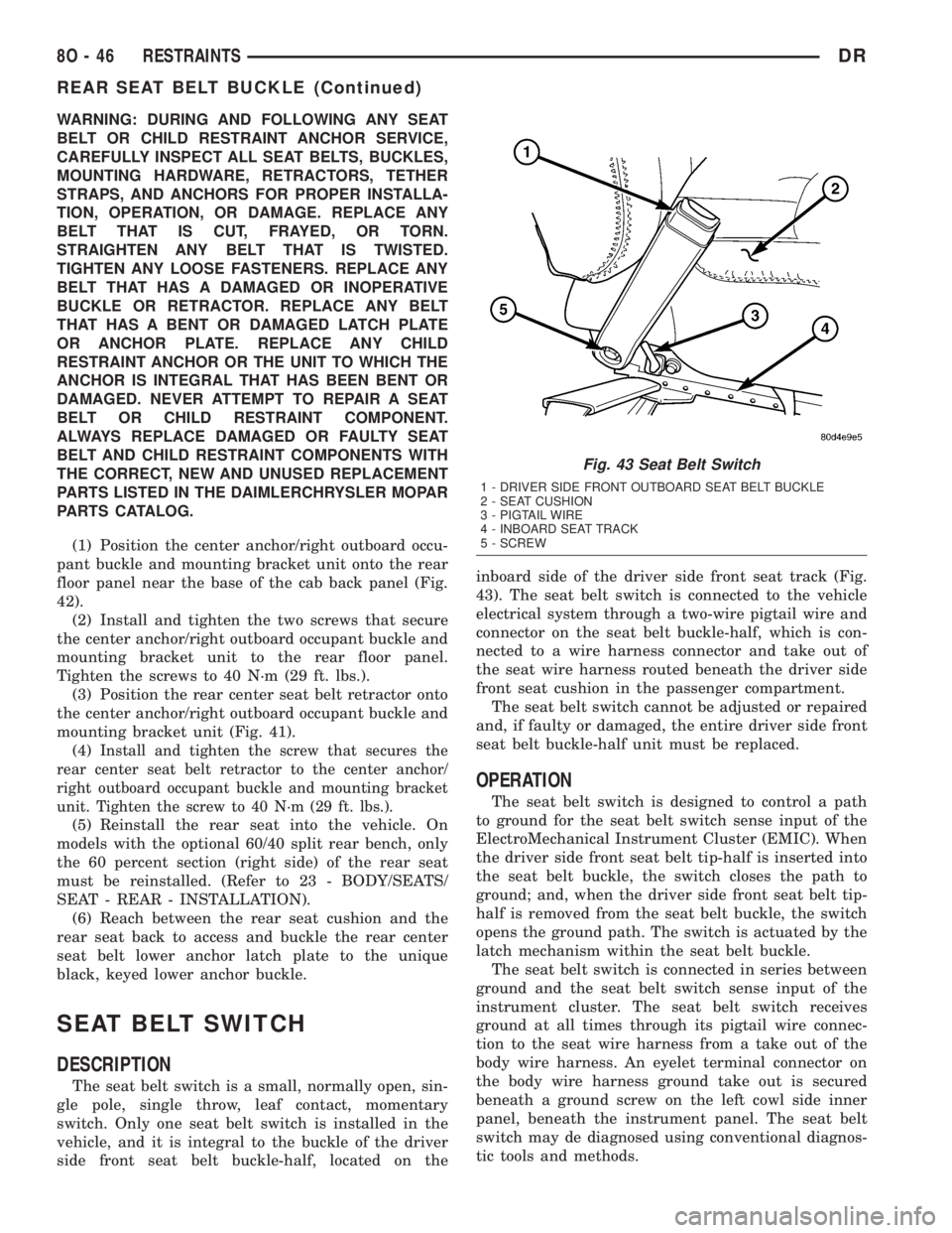
side front seat belt buckle-half, located on theinboard side of the driver side front seat track (Fig.
43). The seat belt switch is connected to the vehicle
electrical system through a two-wire pigtail wire and
connector on the seat belt buckle-half, which is con-
nected to a wire harness connector and take out of
the seat wire harness routed beneath the driver side
front seat cushion in the passenger compartment.
The seat belt switch cannot be adjusted or repaired
and, if faulty or damaged, the entire driver side front
seat belt buckle-half unit must be replaced.
OPERATION
The seat belt switch is designed to control a path
to ground for the seat belt switch sense input of the
ElectroMechanical Instrument Cluster (EMIC). When
the driver side front seat belt tip-half is inserted into
the seat belt buckle, the switch closes the path to
ground; and, when the driver side front seat belt tip-
half is removed from the seat belt buckle, the switch
opens the ground path. The switch is actuated by the
latch mechanism within the seat belt buckle.
The seat belt switch is connected in series between
ground and the seat belt switch sense input of the
instrument cluster. The seat belt switch receives
ground at all times through its pigtail wire connec-
tion to the seat wire harness from a take out of the
body wire harness. An eyelet terminal connector on
the body wire harness ground take out is secured
beneath a ground screw on the left cowl side inner
panel, beneath the instrument panel. The seat belt
switch may de diagnosed using conventional diagnos-
tic tools and methods.
Fig. 43 Seat Belt Switch
1 - DRIVER SIDE FRONT OUTBOARD SEAT BELT BUCKLE
2 - SEAT CUSHION
3 - PIGTAIL WIRE
4 - INBOARD SEAT TRACK
5 - SCREW
8O - 46 RESTRAINTSDR
REAR SEAT BELT BUCKLE (Continued)
Page 648 of 2895
DIAGNOSIS AND TESTING - SEAT BELT
SWITCH
Refer to the appropriate wiring information. The
wiring information includes wiring diagrams, proper
wire and connector repair procedures, details of wire
harness routing and retention, connector pin-out
information and location views for the various wire
harness connectors, splices and grounds.
WARNING: ON VEHICLES EQUIPPED WITH AIR-
BAGS, DISABLE THE SUPPLEMENTAL RESTRAINT
SYSTEM BEFORE ATTEMPTING ANY STEERING
WHEEL, STEERING COLUMN, DRIVER AIRBAG,
PASSENGER AIRBAG, SEAT BELT TENSIONER,
SIDE CURTAIN AIRBAG, OR INSTRUMENT PANEL
COMPONENT DIAGNOSIS OR SERVICE. DISCON-
NECT AND ISOLATE THE BATTERY NEGATIVE
(GROUND) CABLE, THEN WAIT TWO MINUTES FOR
THE SYSTEM CAPACITOR TO DISCHARGE BEFORE
PERFORMING FURTHER DIAGNOSIS OR SERVICE.
THIS IS THE ONLY SURE WAY TO DISABLE THE
SUPPLEMENTAL RESTRAINT SYSTEM. FAILURE TO
TAKE THE PROPER PRECAUTIONS COULD
RESULT IN ACCIDENTAL AIRBAG DEPLOYMENT
AND POSSIBLE PERSONAL INJURY.
(1) Disconnect and isolate the battery negative
cable. Disconnect the seat belt switch pigtail wire
connector from the seat wire harness connector for
the seat belt switch on the inboard side of the driver
side front seat forward of the seat belt buckle-half
anchor. Check for continuity between the seat belt
switch sense circuit and the ground circuit cavities of
the seat belt switch pigtail wire connector. There
should be continuity with the seat belt buckled, and
no continuity with the seat belt unbuckled. If OK, go
to Step 2. If not OK, replace the faulty front seat belt
buckle-half assembly.
(2) Check for continuity between the ground cir-
cuit cavity in the seat wire harness connector for the
seat belt switch and a good ground. There should be
continuity. If OK, go to Step 3. If not OK, repair the
open ground circuit to ground (G301) as required.
(3) Remove the instrument cluster from the instru-
ment panel. Check for continuity between the seat
belt switch sense circuit cavity of the seat wire har-
ness connector for the seat belt switch and a good
ground. There should be no continuity. If OK, go to
Step 4. If not OK, repair the shorted seat belt switch
sense circuit between the seat belt switch and the
instrument cluster as required.
(4) Check for continuity between the seat belt
switch sense circuit cavities of the seat wire harness
connector for the seat belt switch and the instrument
panel wire harness connector (Connector C2) for the
instrument cluster. There should be continuity. IfOK, test and replace the faulty instrument cluster as
required. (Refer to 8 - ELECTRICAL/INSTRUMENT
CLUSTER - DIAGNOSIS AND TESTING). If not OK,
repair the open seat belt switch sense circuit between
the seat belt switch and the instrument cluster as
required.
SEAT BELT TENSIONER
DESCRIPTION
Front outboard seating position seat belt tension-
ers supplement the driver and passenger airbags for
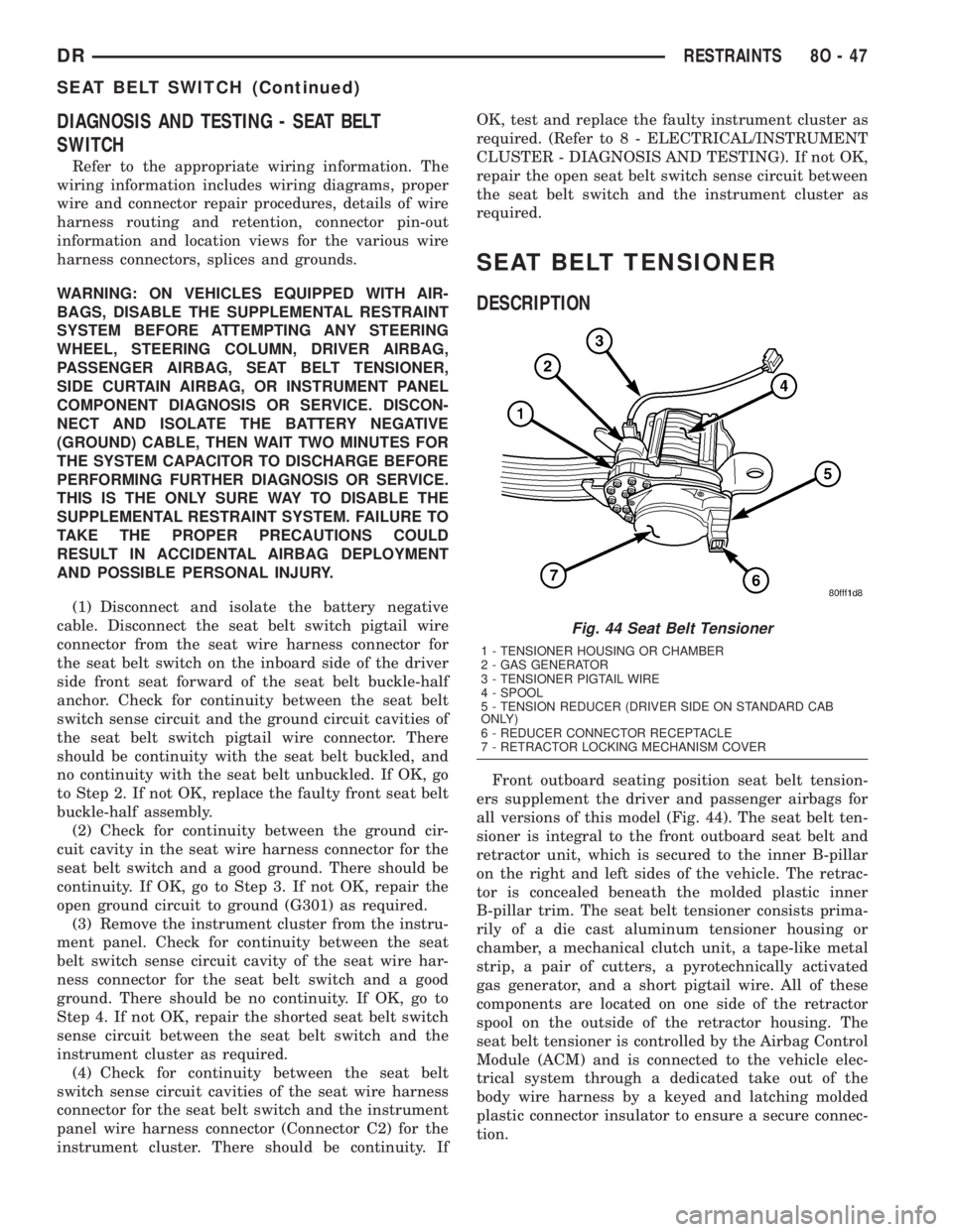
all versions of this model (Fig. 44). The seat belt ten-
sioner is integral to the front outboard seat belt and
retractor unit, which is secured to the inner B-pillar
on the right and left sides of the vehicle. The retrac-
tor is concealed beneath the molded plastic inner
B-pillar trim. The seat belt tensioner consists prima-
rily of a die cast aluminum tensioner housing or
chamber, a mechanical clutch unit, a tape-like metal
strip, a pair of cutters, a pyrotechnically activated
gas generator, and a short pigtail wire. All of these
components are located on one side of the retractor
spool on the outside of the retractor housing. The
seat belt tensioner is controlled by the Airbag Control
Module (ACM) and is connected to the vehicle elec-
trical system through a dedicated take out of the
body wire harness by a keyed and latching molded
plastic connector insulator to ensure a secure connec-
tion.
Fig. 44 Seat Belt Tensioner
1 - TENSIONER HOUSING OR CHAMBER
2 - GAS GENERATOR
3 - TENSIONER PIGTAIL WIRE
4 - SPOOL
5 - TENSION REDUCER (DRIVER SIDE ON STANDARD CAB
ONLY)
6 - REDUCER CONNECTOR RECEPTACLE
7 - RETRACTOR LOCKING MECHANISM COVER
DRRESTRAINTS 8O - 47
SEAT BELT SWITCH (Continued)
Page 649 of 2895
The seat belt tensioner cannot be repaired and, if
faulty or damaged, the entire outboard front seat belt
and retractor unit must be replaced. If the front air-
bags have been deployed, the seat belt tensioners
have also been deployed. The seat belt tensioner is
not intended for reuse and must be replaced follow-
ing a deployment. A locked retractor that will not
allow the seat belt webbing to be retracted or
extracted is a sure indication that the seat belt ten-
sioner has been deployed and requires replacement.
(Refer to 8 - ELECTRICAL/RESTRAINTS/FRONT
OUTBOARD SEAT BELT & RETRACTOR - REMOV-
AL).
OPERATION
The seat belt tensioners are deployed by a signal
generated by the Airbag Control Module (ACM)
through the driver and passenger seat belt tensioner
line 1 and line 2 (or squib) circuits. When the ACM
sends the proper electrical signal to the tensioners,
the electrical energy generates enough heat to ini-
tiate a small pyrotechnic gas generator. The gas gen-
erator is installed at the top of the tensioner housing
which contains a long metal tape that is routed
through two chambers within the housing. Each end
of the tape is wound around the outer sleeve of a
mechanical clutch mechanism secured to one end of
the torsion bar upon which the retractor spool is
secured. As the gas expands, it is directed against
the metal tape within the two chambers of the hous-
ing causing the tape to unwind from the clutch
sleeve. As the clutch rotates it engages the torsion
bar, which drives the seat belt retractor spool causing
the slack to be removed from the seat belt.
Once a seat belt tensioning sequence has been
completed, the forward momentum of the occupant
results in deformation of the torsion bar. As the tor-
sion bar deforms it allows the seat belt webbing to
unwind from the retractor spool, which causes the
metal tape to be wound back onto the clutch sleeve
until it is pulled tight against two cutter blades
within the housing, which immediately cut the metal
tape.
Removing excess slack from the seat belt not only
keeps the occupant properly positioned for an airbag
deployment following a frontal impact of the vehicle,
but also helps to reduce injuries that the occupant
might experience in these situations as a result of a
harmful contact with the steering wheel, steering col-
umn, instrument panel and/or windshield. The tor-
sion bar is designed to deform in order to control the
loading being applied to the occupant by the seat belt
during a frontal impact, further reducing the poten-
tial for occupant injuries.
The ACM monitors the condition of the seat belt
tensioners through circuit resistance. The ACM willilluminate the airbag indicator in the ElectroMe-
chanical Instrument Cluster (EMIC) and store a
Diagnostic Trouble Code (DTC) for any fault that is
detected. For proper diagnosis of the seat belt ten-
sioners, a DRBIIItscan tool is required. Refer to the
appropriate diagnostic information.
SEAT BELT TENSION
REDUCER
DESCRIPTION
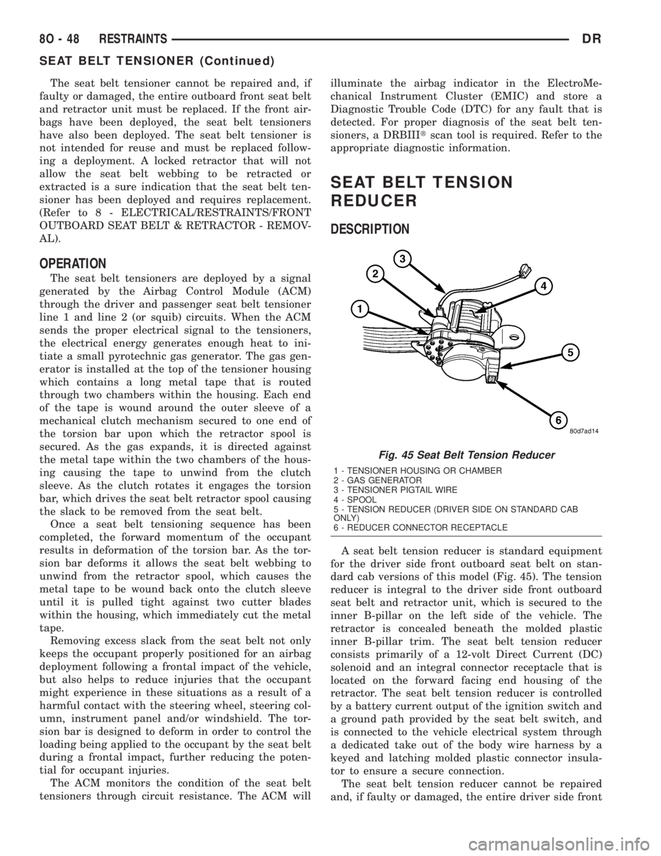
A seat belt tension reducer is standard equipment
for the driver side front outboard seat belt on stan-
dard cab versions of this model (Fig. 45). The tension
reducer is integral to the driver side front outboard
seat belt and retractor unit, which is secured to the
inner B-pillar on the left side of the vehicle. The
retractor is concealed beneath the molded plastic
inner B-pillar trim. The seat belt tension reducer
consists primarily of a 12-volt Direct Current (DC)
solenoid and an integral connector receptacle that is
located on the forward facing end housing of the
retractor. The seat belt tension reducer is controlled
by a battery current output of the ignition switch and
a ground path provided by the seat belt switch, and
is connected to the vehicle electrical system through
a dedicated take out of the body wire harness by a
keyed and latching molded plastic connector insula-
tor to ensure a secure connection.
The seat belt tension reducer cannot be repaired
and, if faulty or damaged, the entire driver side front
Fig. 45 Seat Belt Tension Reducer
1 - TENSIONER HOUSING OR CHAMBER
2 - GAS GENERATOR
3 - TENSIONER PIGTAIL WIRE
4 - SPOOL
5 - TENSION REDUCER (DRIVER SIDE ON STANDARD CAB
ONLY)
6 - REDUCER CONNECTOR RECEPTACLE
8O - 48 RESTRAINTSDR
SEAT BELT TENSIONER (Continued)
Page 650 of 2895
outboard seat belt and retractor unit must be
replaced. (Refer to 8 - ELECTRICAL/RESTRAINTS/
FRONT OUTBOARD SEAT BELT & RETRACTOR -
REMOVAL).
OPERATION
The seat belt tension reducer is controlled by a
ground signal received from the seat belt switch on
the seat belt switch sense circuit and a battery cur-
rent signal received from the ignition switch on the
fused ignition switch output (run-accessory) circuit.
When the seat belt switch is closed (the driver side
front seat belt is fastened) and the ignition switch is
in the On or Accessory positions, the seat belt tension
reducer solenoid is energized. When the solenoid is
energized, it actuates a mechanism within the driver
side front outboard seat belt retractor to reduce the
normal recoil spring tension exerted by the retractor
spool, which is designed to reel in the seat belt web-
bing onto the spool. When the driver side seat belt is
unbuckled or if the ignition switch is turned to any
position except On or Accessory, the tension reducer
solenoid is de-energized and the normal recoil spring
tension of the retractor is restored.
The action of the seat belt tension reducer results
in improved seat belt comfort for the driver. Reducing
the seat belt retractor recoil spring tension is desir-
able on standard cab models of this vehicle and not
on the quad cab model due to the different mounting
position required for the seat belt turning loop on the
B-pillar relative to the driver's seat position on the
standard cab model. The seat belt tension reducer
may be diagnosed using conventional diagnostic tools
and methods.
DIAGNOSIS AND TESTING - SEAT BELT
TENSION REDUCER
Refer to the appropriate wiring information. The
wiring information includes wiring diagrams, proper
wire and connector repair procedures, details of wire
harness routing and retention, connector pin-out
information and location views for the various wire
harness connectors, splices and grounds.
WARNING: ON VEHICLES EQUIPPED WITH AIR-
BAGS, DISABLE THE SUPPLEMENTAL RESTRAINTSYSTEM BEFORE ATTEMPTING ANY STEERING
WHEEL, STEERING COLUMN, DRIVER AIRBAG,
PASSENGER AIRBAG, SEAT BELT TENSIONER,
SIDE CURTAIN AIRBAG, OR INSTRUMENT PANEL
COMPONENT DIAGNOSIS OR SERVICE. DISCON-
NECT AND ISOLATE THE BATTERY NEGATIVE
(GROUND) CABLE, THEN WAIT TWO MINUTES FOR
THE SYSTEM CAPACITOR TO DISCHARGE BEFORE
PERFORMING FURTHER DIAGNOSIS OR SERVICE.
THIS IS THE ONLY SURE WAY TO DISABLE THE
SUPPLEMENTAL RESTRAINT SYSTEM. FAILURE TO
TAKE THE PROPER PRECAUTIONS COULD
RESULT IN ACCIDENTAL AIRBAG DEPLOYMENT
AND POSSIBLE PERSONAL INJURY.
(1) Disconnect and isolate the battery negative
cable. Disconnect the body wire harness connector for
the seat belt tension reducer from the tension
reducer connector receptacle on the driver side front
outboard seat belt and retractor unit. Using an ohm-
meter, measure the resistance between the seat belt
switch sense circuit terminal pin and the fused igni-
tion switch output (run-accessory) circuit terminal
pin in the tension reducer connector receptacle on
the retractor. Resistance through the tension reducer
solenoid coil should be 53 ohms at 20É C (68É F). If
OK, go to Step 2. If not OK, replace the faulty driver
side front outboard seat belt and retractor unit.
(2) Check for continuity between the seat belt
switch sense circuit cavity of the body wire harness
connector for the seat belt tension reducer and a good
ground. There should be continuity with the driver
side front seat belt buckled, and no continuity with
the driver side front seat belt unbuckled. If OK, go to
Step 3. If not OK, repair the shorted or open seat
belt switch sense circuit between the tension reducer
and the seat belt switch as required.
(3) Reconnect the battery negative cable. Check for
battery current at the fused ignition switch output
(run-accessory) circuit of the body wire harness con-
nector for the seat belt tension reducer. There should
be battery current with the ignition switch in the On
or Accessory positions, and no battery current with
the ignition switch in any other position. If not OK,
repair the shorted or open fused ignition switch out-
put (run-accessory) circuit between the tension
reducer and the ignition switch as required.
DRRESTRAINTS 8O - 49
SEAT BELT TENSION REDUCER (Continued)