Throttle Position Sensor DODGE RAM 2003 Service Manual Online
[x] Cancel search | Manufacturer: DODGE, Model Year: 2003, Model line: RAM, Model: DODGE RAM 2003Pages: 2895, PDF Size: 83.15 MB
Page 2215 of 2895
ADJUSTMENTS - BRAKE TRANSMISSION
SHIFT INTERLOCK
Correct cable adjustment is important to proper
interlock operation. The gearshift cable must be cor-
rectly adjusted in order to shift out of PARK.
ADJUSTMENT PROCEDURE
(1) Remove the steering column trim as necessary
for access to the brake transmission shift interlock.
(2) Shift the transmission into the PARK position.
(3) Pull upward on both the BTSI lock tab and the
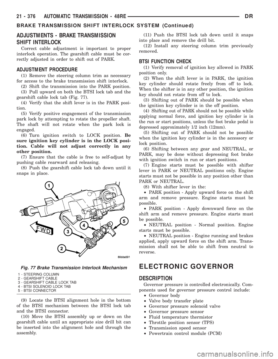
gearshift cable lock tab (Fig. 77).
(4) Verify that the shift lever is in the PARK posi-
tion.
(5) Verify positive engagement of the transmission
park lock by attempting to rotate the propeller shaft.
The shaft will not rotate when the park lock is
engaged.
(6) Turn ignition switch to LOCK position.Be
sure ignition key cylinder is in the LOCK posi-
tion. Cable will not adjust correctly in any
other position.
(7) Ensure that the cable is free to self-adjust by
pushing cable rearward and releasing.
(8) Push the gearshift cable lock tab down until it
snaps in place.
(9) Locate the BTSI alignment hole in the bottom
of the BTSI mechanism between the BTSI lock tab
and the BTSI connector.
(10) Move the BTSI assembly up or down on the
gearshift cable until an appropriate size drill bit can
be inserted into the alignment hole and through the
assembly.(11) Push the BTSI lock tab down until it snaps
into place and remove the drill bit.
(12) Install any steering column trim previously
removed.
BTSI FUNCTION CHECK
(1) Verify removal of ignition key allowed in PARK
position only.
(2) When the shift lever is in PARK, the ignition
key cylinder should rotate freely from off to lock.
When the shifter is in any other position, the ignition
key should not rotate from off to lock.
(3) Shifting out of PARK should be possible when
the ignition key cylinder is in the off position.
(4)
Shifting out of PARK should not be possible while
applying normal force, and ignition key cylinder is in
the run or start positions, unless the foot brake pedal is
depressed approximately 1/2 inch (12mm).
(5) Shifting out of PARK should not be possible
when the ignition key cylinder is in the accessory or
lock position.
(6) Shifting between any gear and NEUTRAL, or
PARK, may be done without depressing foot brake
with ignition switch in run or start positions.
(7) Engine starts must be possible with shifter
lever in PARK or NEUTRAL positions only. Engine
starts must not be possible in any position other than
PARK or NEUTRAL.
(8) With shifter lever in the:
²PARK position - Apply upward force on the shift
arm and remove pressure. Engine starts must be
possible.
²PARK position - Apply downward force on the
shift arm and remove pressure. Engine starts must
be possible.
²NEUTRAL position - Normal position. Engine
starts must be possible.
²NEUTRAL position - Engine running and brakes
applied, apply upward force on the shift arm. Trans-
mission shall not be able to shift from neutral to
reverse.
ELECTRONIC GOVERNOR
DESCRIPTION
Governor pressure is controlled electronically. Com-
ponents used for governor pressure control include:
²Governor body
²Valve body transfer plate
²Governor pressure solenoid valve
²Governor pressure sensor
²Fluid temperature thermistor
²Throttle position sensor (TPS)
²Transmission speed sensor
²Powertrain control module (PCM)
Fig. 77 Brake Transmission Interlock Mechanism
1 - STEERING COLUMN
2 - GEARSHIFT CABLE
3 - GEARSHIFT CABLE LOCK TAB
4 - BTSI SOLENOID LOCK TAB
5 - BTSI CONNECTOR
21 - 376 AUTOMATIC TRANSMISSION - 48REDR
BRAKE TRANSMISSION SHIFT INTERLOCK SYSTEM (Continued)
Page 2217 of 2895
GOVERNOR PRESSURE SENSOR
The sensor output signal provides the necessary
feedback to the PCM. This feedback is needed to ade-
quately control governor pressure.
GOVERNOR BODY AND TRANSFER PLATE
The transfer plate channels line pressure to the
solenoid valve through the governor body. It also
channels governor pressure from the solenoid valve
to the governor circuit. It is the solenoid valve that
develops the necessary governor pressure.
GOVERNOR PRESSURE CURVES
LOW TRANSMISSION FLUID TEMPERATURE
When the transmission fluid is cold the conven-
tional governor can delay shifts, resulting in higher
than normal shift speeds and harsh shifts. The elec-
tronically controlled low temperature governor pres-
sure curve is higher than normal to make the
transmission shift at normal speeds and sooner. The
PCM uses a temperature sensor in the transmission
oil sump to determine when low temperature gover-
nor pressure is needed.
NORMAL OPERATION
Normal operation is refined through the increased
computing power of the PCM and through access to
data on engine operating conditions provided by the
PCM that were not available with the previous
stand-alone electronic module. This facilitated the
development of a load adaptive shift strategy - the
ability to alter the shift schedule in response to vehi-
cle load condition. One manifestation of this capabil-
ity is grade9hunting9prevention - the ability of the
transmission logic to delay an upshift on a grade if
the engine does not have sufficient power to main-
tain speed in the higher gear. The 3-2 downshift and
the potential for hunting between gears occurs with a
heavily loaded vehicle or on steep grades. When
hunting occurs, it is very objectionable because shifts
are frequent and accompanied by large changes in
noise and acceleration.
WIDE OPEN THROTTLE OPERATION
In wide-open throttle (WOT) mode, adaptive mem-
ory in the PCM assures that up-shifts occur at the
preprogrammed optimum speed. WOT operation is
determined from the throttle position sensor, which
is also a part of the emission control system. The ini-tial setting for the WOT upshift is below the opti-
mum engine speed. As WOT shifts are repeated, the
PCM learns the time required to complete the shifts
by comparing the engine speed when the shifts occur
to the optimum speed. After each shift, the PCM
adjusts the shift point until the optimum speed is
reached. The PCM also considers vehicle loading,
grade and engine performance changes due to high
altitude in determining when to make WOT shifts. It
does this by measuring vehicle and engine accelera-
tion and then factoring in the shift time.
TRANSFER CASE LOW RANGE OPERATION
On four-wheel drive vehicles operating in low
range, the engine can accelerate to its peak more
rapidly than in Normal range, resulting in delayed
shifts and undesirable engine9flare.9The low range
governor pressure curve is also higher than normal
to initiate upshifts sooner. The PCM compares elec-
tronic vehicle speed signal used by the speedometer
to the transmission output shaft speed signal to
determine when the transfer case is in low range.
REMOVAL
(1) Hoist and support vehicle on safety stands.
(2) Remove transmission fluid pan and filter.
(3) Disengage wire connectors from pressure sen-
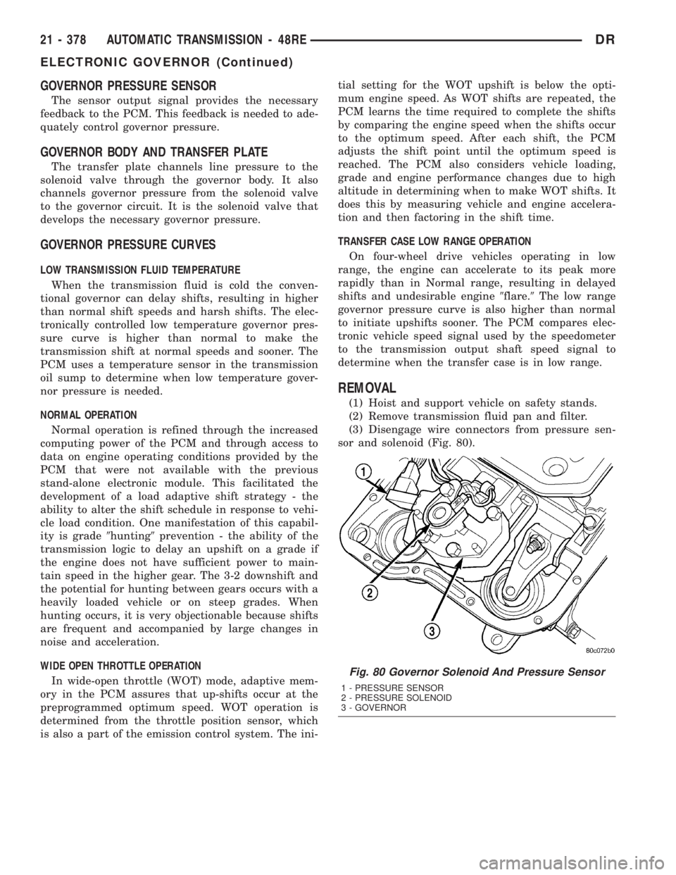
sor and solenoid (Fig. 80).
Fig. 80 Governor Solenoid And Pressure Sensor
1 - PRESSURE SENSOR
2 - PRESSURE SOLENOID
3 - GOVERNOR
21 - 378 AUTOMATIC TRANSMISSION - 48REDR
ELECTRONIC GOVERNOR (Continued)
Page 2303 of 2895
BOOST VALVE
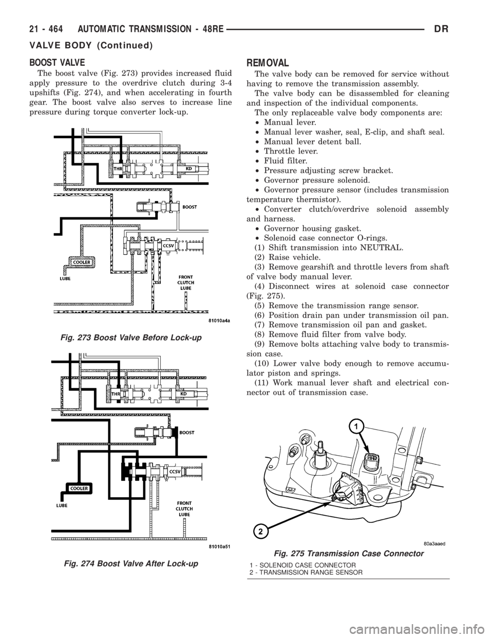
The boost valve (Fig. 273) provides increased fluid
apply pressure to the overdrive clutch during 3-4
upshifts (Fig. 274), and when accelerating in fourth
gear. The boost valve also serves to increase line
pressure during torque converter lock-up.
REMOVAL
The valve body can be removed for service without
having to remove the transmission assembly.
The valve body can be disassembled for cleaning
and inspection of the individual components.
The only replaceable valve body components are:
²Manual lever.
²
Manual lever washer, seal, E-clip, and shaft seal.
²Manual lever detent ball.
²Throttle lever.
²Fluid filter.
²Pressure adjusting screw bracket.
²Governor pressure solenoid.
²Governor pressure sensor (includes transmission
temperature thermistor).
²Converter clutch/overdrive solenoid assembly
and harness.
²Governor housing gasket.
²Solenoid case connector O-rings.
(1) Shift transmission into NEUTRAL.
(2) Raise vehicle.
(3) Remove gearshift and throttle levers from shaft
of valve body manual lever.
(4) Disconnect wires at solenoid case connector
(Fig. 275).
(5) Remove the transmission range sensor.
(6) Position drain pan under transmission oil pan.
(7) Remove transmission oil pan and gasket.
(8) Remove fluid filter from valve body.
(9) Remove bolts attaching valve body to transmis-
sion case.
(10) Lower valve body enough to remove accumu-
lator piston and springs.
(11) Work manual lever shaft and electrical con-
nector out of transmission case.
Fig. 275 Transmission Case Connector
1 - SOLENOID CASE CONNECTOR
2 - TRANSMISSION RANGE SENSOR
Fig. 273 Boost Valve Before Lock-up
Fig. 274 Boost Valve After Lock-up
21 - 464 AUTOMATIC TRANSMISSION - 48REDR
VALVE BODY (Continued)
Page 2315 of 2895
3-4 ACCUMULATOR HOUSING
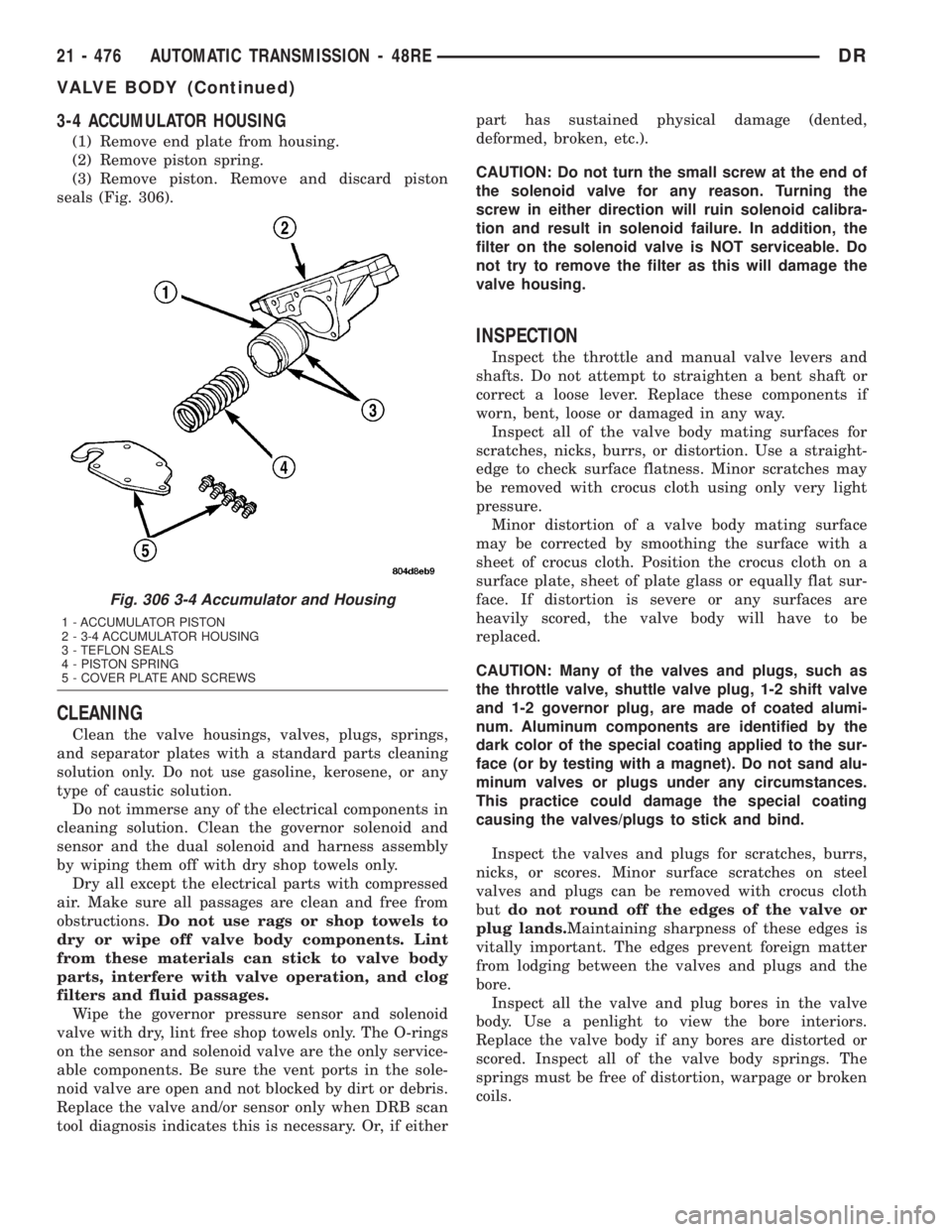
(1) Remove end plate from housing.
(2) Remove piston spring.
(3) Remove piston. Remove and discard piston
seals (Fig. 306).
CLEANING
Clean the valve housings, valves, plugs, springs,
and separator plates with a standard parts cleaning
solution only. Do not use gasoline, kerosene, or any
type of caustic solution.
Do not immerse any of the electrical components in
cleaning solution. Clean the governor solenoid and
sensor and the dual solenoid and harness assembly
by wiping them off with dry shop towels only.
Dry all except the electrical parts with compressed
air. Make sure all passages are clean and free from
obstructions.Do not use rags or shop towels to
dry or wipe off valve body components. Lint
from these materials can stick to valve body
parts, interfere with valve operation, and clog
filters and fluid passages.
Wipe the governor pressure sensor and solenoid
valve with dry, lint free shop towels only. The O-rings
on the sensor and solenoid valve are the only service-
able components. Be sure the vent ports in the sole-
noid valve are open and not blocked by dirt or debris.
Replace the valve and/or sensor only when DRB scan
tool diagnosis indicates this is necessary. Or, if eitherpart has sustained physical damage (dented,
deformed, broken, etc.).
CAUTION: Do not turn the small screw at the end of
the solenoid valve for any reason. Turning the
screw in either direction will ruin solenoid calibra-
tion and result in solenoid failure. In addition, the
filter on the solenoid valve is NOT serviceable. Do
not try to remove the filter as this will damage the
valve housing.
INSPECTION
Inspect the throttle and manual valve levers and
shafts. Do not attempt to straighten a bent shaft or
correct a loose lever. Replace these components if
worn, bent, loose or damaged in any way.
Inspect all of the valve body mating surfaces for
scratches, nicks, burrs, or distortion. Use a straight-
edge to check surface flatness. Minor scratches may
be removed with crocus cloth using only very light
pressure.
Minor distortion of a valve body mating surface
may be corrected by smoothing the surface with a
sheet of crocus cloth. Position the crocus cloth on a
surface plate, sheet of plate glass or equally flat sur-
face. If distortion is severe or any surfaces are
heavily scored, the valve body will have to be
replaced.
CAUTION: Many of the valves and plugs, such as
the throttle valve, shuttle valve plug, 1-2 shift valve
and 1-2 governor plug, are made of coated alumi-
num. Aluminum components are identified by the
dark color of the special coating applied to the sur-
face (or by testing with a magnet). Do not sand alu-
minum valves or plugs under any circumstances.
This practice could damage the special coating
causing the valves/plugs to stick and bind.
Inspect the valves and plugs for scratches, burrs,
nicks, or scores. Minor surface scratches on steel
valves and plugs can be removed with crocus cloth
butdo not round off the edges of the valve or
plug lands.Maintaining sharpness of these edges is
vitally important. The edges prevent foreign matter
from lodging between the valves and plugs and the
bore.
Inspect all the valve and plug bores in the valve
body. Use a penlight to view the bore interiors.
Replace the valve body if any bores are distorted or
scored. Inspect all of the valve body springs. The
springs must be free of distortion, warpage or broken
coils.
Fig. 306 3-4 Accumulator and Housing
1 - ACCUMULATOR PISTON
2 - 3-4 ACCUMULATOR HOUSING
3 - TEFLON SEALS
4 - PISTON SPRING
5 - COVER PLATE AND SCREWS
21 - 476 AUTOMATIC TRANSMISSION - 48REDR
VALVE BODY (Continued)
Page 2325 of 2895
(20)Install solenoid assembly and gasket. Tighten
solenoid attaching screws to 8 N´m (72 in. lbs.) torque.
(21) Verify that solenoid wire harness is properly
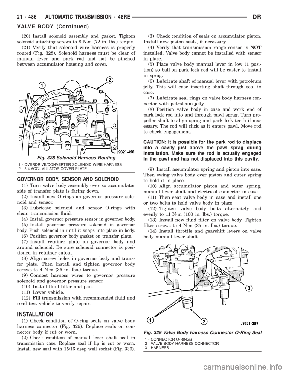
routed (Fig. 328). Solenoid harness must be clear of
manual lever and park rod and not be pinched
between accumulator housing and cover.
GOVERNOR BODY, SENSOR AND SOLENOID
(1) Turn valve body assembly over so accumulator
side of transfer plate is facing down.
(2) Install new O-rings on governor pressure sole-
noid and sensor.
(3) Lubricate solenoid and sensor O-rings with
clean transmission fluid.
(4)
Install governor pressure sensor in governor body.
(5)Install governor pressure solenoid in governor
body. Push solenoid in until it snaps into place in body.
(6)Position governor body gasket on transfer plate.
(7) Install retainer plate on governor body and
around solenoid. Be sure solenoid connector is posi-
tioned in retainer cutout.
(8) Align screw holes in governor body and trans-
fer plate. Then install and tighten governor body
screws to 4 N´m (35 in. lbs.) torque.
(9) Connect harness wires to governor pressure
solenoid and governor pressure sensor.
(10) Install fluid filter and pan.
(11) Lower vehicle.
(12) Fill transmission with recommended fluid and
road test vehicle to verify repair.
INSTALLATION
(1) Check condition of O-ring seals on valve body
harness connector (Fig. 329). Replace seals on con-
nector body if cut or worn.
(2)
Check condition of manual lever shaft seal in
transmission case. Replace seal if lip is cut or worn.
Install new seal with 15/16 deep well socket (Fig. 330).
(3) Check condition of seals on accumulator piston.
Install new piston seals, if necessary.
(4) Verify that transmission range sensor isNOT
installed. Valve body cannot be installed with sensor
in place.
(5) Place valve body manual lever in low (1 posi-
tion) so ball on park lock rod will be easier to install
in sprag.
(6) Lubricate shaft of manual lever with petroleum
jelly. This will ease inserting shaft through seal in
case.
(7) Lubricate seal rings on valve body harness con-
nector with petroleum jelly.
(8) Position valve body in case and work end of
park lock rod into and through pawl sprag. Turn pro-
peller shaft to align sprag and park lock teeth if nec-
essary. The rod will click as it enters pawl. Move rod
to check engagement.
CAUTION: It is possible for the park rod to displace
into a cavity just above the pawl sprag during
installation. Make sure the rod is actually engaged
in the pawl and has not displaced into this cavity.
(9) Install accumulator spring and piston into case.
Then swing valve body over piston and outer spring
to hold it in place.
(10) Align accumulator piston and outer spring,
manual lever shaft and electrical connector in case.
(11) Then seat valve body in case and install one
or two bolts to hold valve body in place.
(12) Tighten valve body bolts alternately and
evenly to 11 N´m (100 in. lbs.) torque.
(13) Install new fluid filter on valve body. Tighten
filter screws to 4 N´m (35 in. lbs.) torque.
(14) Install throttle and gearshift levers on valve
body manual lever shaft.
Fig. 329 Valve Body Harness Connector O-Ring Seal
1 - CONNECTOR O-RINGS
2 - VALVE BODY HARNESS CONNECTOR
3 - HARNESS
Fig. 328 Solenoid Harness Routing
1 - OVERDRIVE/CONVERTER SOLENOID WIRE HARNESS
2 - 3-4 ACCUMULATOR COVER PLATE
21 - 486 AUTOMATIC TRANSMISSION - 48REDR
VALVE BODY (Continued)
Page 2326 of 2895
(15) Check and adjust front and rear bands if nec-
essary.
(16) Connect solenoid case connector wires.
(17) Install the transmission range sensor.
(18) Install oil pan and new gasket. Tighten pan
bolts to 17 N´m (13 ft. lbs.) torque.
(19) Lower vehicle and fill transmission with
MopartATF +4, Automatic Transmission fluid.
(20) Check and adjust gearshift and throttle valve
cables, if necessary.
ADJUSTMENTS - VALVE BODY
CONTROL PRESSURE ADJUSTMENTS
There are two control pressure adjustments on the
valve body;
²Line Pressure
²Throttle Pressure
Line and throttle pressures are interdependent
because each affects shift quality and timing. As a
result, both adjustments must be performed properly
and in the correct sequence. Adjust line pressure first
and throttle pressure last.
LINE PRESSURE ADJUSTMENT
Measure distance from the valve body to the inner
edge of the adjusting screw with an accurate steel
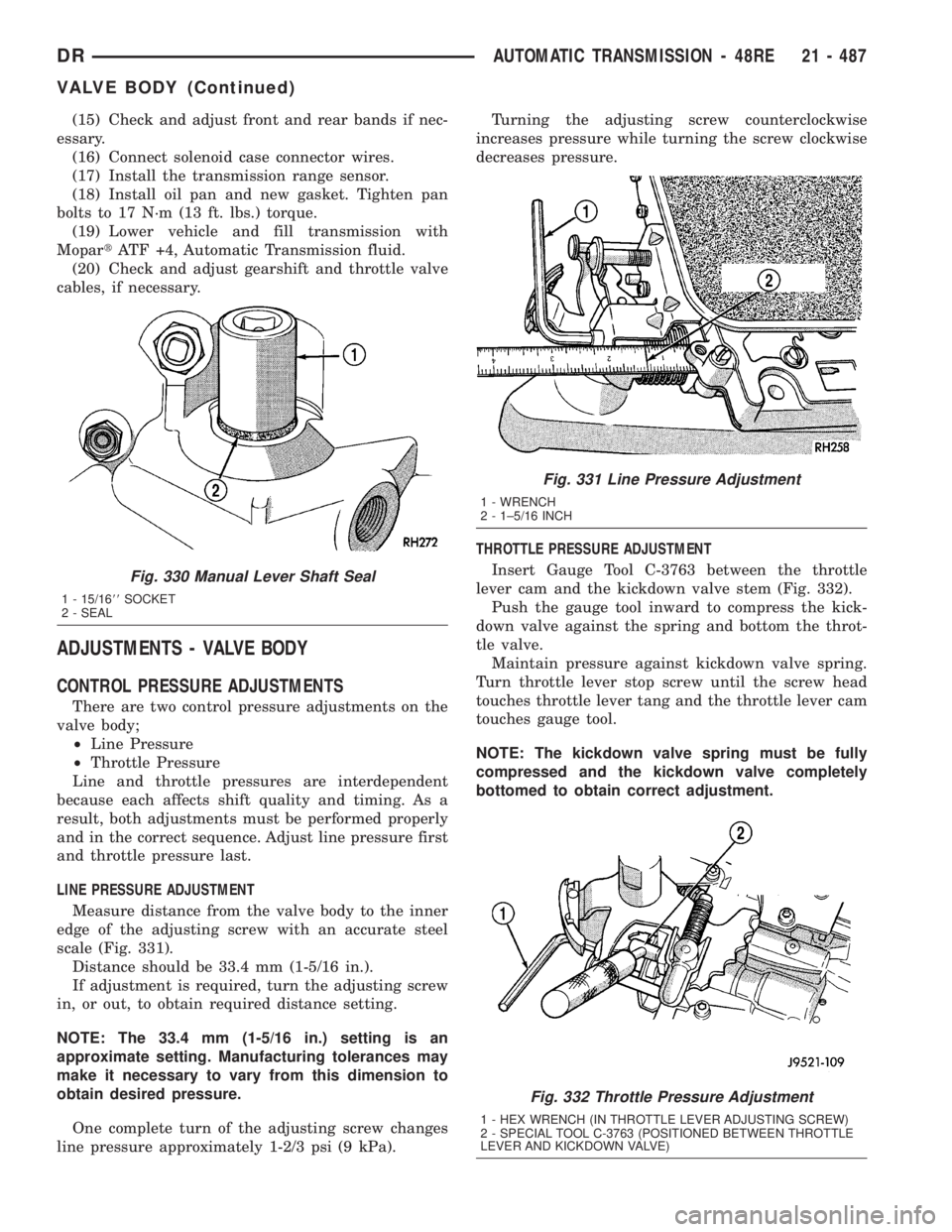
scale (Fig. 331).
Distance should be 33.4 mm (1-5/16 in.).
If adjustment is required, turn the adjusting screw
in, or out, to obtain required distance setting.
NOTE: The 33.4 mm (1-5/16 in.) setting is an
approximate setting. Manufacturing tolerances may
make it necessary to vary from this dimension to
obtain desired pressure.
One complete turn of the adjusting screw changes
line pressure approximately 1-2/3 psi (9 kPa).Turning the adjusting screw counterclockwise
increases pressure while turning the screw clockwise
decreases pressure.
THROTTLE PRESSURE ADJUSTMENT
Insert Gauge Tool C-3763 between the throttle
lever cam and the kickdown valve stem (Fig. 332).
Push the gauge tool inward to compress the kick-
down valve against the spring and bottom the throt-
tle valve.
Maintain pressure against kickdown valve spring.
Turn throttle lever stop screw until the screw head
touches throttle lever tang and the throttle lever cam
touches gauge tool.
NOTE: The kickdown valve spring must be fully
compressed and the kickdown valve completely
bottomed to obtain correct adjustment.
Fig. 330 Manual Lever Shaft Seal
1 - 15/1688SOCKET
2 - SEAL
Fig. 331 Line Pressure Adjustment
1 - WRENCH
2 - 1±5/16 INCH
Fig. 332 Throttle Pressure Adjustment
1 - HEX WRENCH (IN THROTTLE LEVER ADJUSTING SCREW)
2 - SPECIAL TOOL C-3763 (POSITIONED BETWEEN THROTTLE
LEVER AND KICKDOWN VALVE)
DRAUTOMATIC TRANSMISSION - 48RE 21 - 487
VALVE BODY (Continued)
Page 2833 of 2895
verter. The PCM calculates the A/F mixture from the
output of the O2S. A low voltage indicates high oxy-
gen content (lean mixture). A high voltage indicates a
low content of oxygen (rich mixture).
When the upstream O2S detects a lean condition,
there is an abundance of oxygen in the exhaust gas.
A functioning converter would store this oxygen so it
can use it for the oxidation of HC and CO. As the
converter absorbs the oxygen, there will be a lack of
oxygen downstream of the converter. The output of
the downstream O2S will indicate limited activity in
this condition.
As the converter loses the ability to store oxygen,
the condition can be detected from the behavior of
the downstream O2S. When the efficiency drops, no
chemical reaction takes place. This means the con-
centration of oxygen will be the same downstream as
upstream. The output voltage of the downstream
O2S copies the voltage of the upstream sensor. The
only difference is a time lag (seen by the PCM)
between the switching of the O2S's.
To monitor the system, the number of lean-to-rich
switches of upstream and downstream O2S's is
counted. The ratio of downstream switches to
upstream switches is used to determine whether the
catalyst is operating properly. An effective catalyst
will have fewer downstream switches than it has
upstream switches i.e., a ratio closer to zero. For a
totally ineffective catalyst, this ratio will be one-to-
one, indicating that no oxidation occurs in the device.
The system must be monitored so that when cata-
lyst efficiency deteriorates and exhaust emissions
increase to over the legal limit, the MIL will be illu-
minated.
DESCRIPTION - TRIP DEFINITION
The term ªTripº has different meanings depending
on what the circumstances are. If the MIL (Malfunc-
tion Indicator Lamp) is OFF, a Trip is defined as
when the Oxygen Sensor Monitor and the Catalyst
Monitor have been completed in the same drive cycle.
When any Emission DTC is set, the MIL on the
dash is turned ON. When the MIL is ON, it takes 3
good trips to turn the MIL OFF. In this case, it
depends on what type of DTC is set to know what a
ªTripº is.
For the Fuel Monitor or Mis-Fire Monitor (contin-
uous monitor), the vehicle must be operated in the
ªSimilar Condition Windowº for a specified amount of
time to be considered a Good Trip.
If a Non-Contiuous OBDII Monitor fails twice in a
row and turns ON the MIL, re-running that monitor
which previously failed, on the next start-up and
passing the monitor, is considered to be a Good Trip.
These will include the following:
²Oxygen Sensor²Catalyst Monitor
²Purge Flow Monitor
²Leak Detection Pump Monitor (if equipped)
²EGR Monitor (if equipped)
²Oxygen Sensor Heater Monitor
If any other Emission DTC is set (not an OBDII
Monitor), a Good Trip is considered to be when the
Oxygen Sensor Monitor and Catalyst Monitor have
been completed; or 2 Minutes of engine run time if
the Oxygen Sensor Monitor or Catalyst Monitor have
been stopped from running.
It can take up to 2 Failures in a row to turn on the
MIL. After the MIL is ON, it takes 3 Good Trips to
turn the MIL OFF. After the MIL is OFF, the PCM
will self-erase the DTC after 40 Warm-up cycles. A
Warm-up cycle is counted when the ECT (Engine
Coolant Temperature Sensor) has crossed 160ÉF and
has risen by at least 40ÉF since the engine has been
started.
DESCRIPTION - COMPONENT MONITORS
There are several components that will affect vehi-
cle emissions if they malfunction. If one of these com-
ponents malfunctions the Malfunction Indicator
Lamp (MIL) will illuminate.
Some of the component monitors are checking for
proper operation of the part. Electrically operated
components now have input (rationality) and output
(functionality) checks. Previously, a component like
the Throttle Position sensor (TPS) was checked by
the PCM for an open or shorted circuit. If one of
these conditions occurred, a DTC was set. Now there
is a check to ensure that the component is working.
This is done by watching for a TPS indication of a
greater or lesser throttle opening than MAP and
engine rpm indicate. In the case of the TPS, if engine
vacuum is high and engine rpm is 1600 or greater,
and the TPS indicates a large throttle opening, a
DTC will be set. The same applies to low vacuum if
the TPS indicates a small throttle opening.
All open/short circuit checks, or any component
that has an associated limp-in, will set a fault after 1
trip with the malfunction present. Components with-
out an associated limp-in will take two trips to illu-
minate the MIL.
OPERATION
OPERATION
The Powertrain Control Module (PCM) monitors
many different circuits in the fuel injection, ignition,
emission and engine systems. If the PCM senses a
problem with a monitored circuit often enough to
indicate an actual problem, it stores a Diagnostic
Trouble Code (DTC) in the PCM's memory. If the
25 - 4 EMISSIONS CONTROLDR
EMISSIONS CONTROL (Continued)
Page 2860 of 2895
BRAKE SYSTEM - DIAGNOSIS AND
TESTING, BASE........................5-2
BRAKE TRANSMISSION SHIFT
INTERLOCK - ADJUSTMENTS . . . 21-195,21-376,
21-540
BRAKE TRANSMISSION SHIFT
INTERLOCK - DIAGNOSIS AND
TESTING..............21-195,21-375,21-540
BRAKE TRANSMISSION SHIFT
INTERLOCK SYSTEM - DESCRIPTION . . . 21-194,
21-375,21-540
BRAKE TRANSMISSION SHIFT
INTERLOCK SYSTEM - OPERATION.....21-194,
21-375,21-540
BRAKE/PARK BRAKE INDICATOR -
DESCRIPTION.......................8J-18
BRAKE/PARK BRAKE INDICATOR -
OPERATION.........................8J-19
BRAKES - ABS - DESCRIPTION...........5-39
BRAKES - ABS - OPERATION............5-39
BRAKES, SPECIAL TOOLS - BASE.........5-5
BREAK-IN - STANDARD PROCEDURE,
A/C COMPRESSOR CLUTCH............24-10
BREATHER - INSTALLATION,
CRANKCASE........................9-292
BREATHER - REMOVAL, CRANKCASE.....9-291
BUCKLE - INSTALLATION, FRONT
OUTBOARD SEAT BELT................8O-34
BUCKLE - REMOVAL, FRONT OUTBOARD
SEAT BELT .........................8O-33
BUILT-IN INDICATOR TEST - STANDARD
PROCEDURE........................8F-10
BUMPER - INSTALLATION, FRONT........13-2
BUMPER - INSTALLATION, JOUNCE.......2-40
BUMPER - INSTALLATION, REAR.........13-4
BUMPER - REMOVAL, FRONT............13-2
BUMPER - REMOVAL, JOUNCE...........2-40
BUMPER - REMOVAL, REAR.............13-4
BUMPERS (3500) - INSTALLATION,
AUXILIARY SPRING....................2-40
BUMPERS (3500) - REMOVAL,
AUXILIARY SPRING....................2-40
BURNT FLUID - DIAGNOSIS AND
TESTING, CAUSES OF....21-201,21-381,21-541
BUSHING - INSTALLATION.............19-18
BUSHING - INSTALLATION,
DISTRIBUTOR.......................9-258
BUSHING - INSTALLATION, EXTENSION
HOUSING..........................21-200
BUSHING - INSTALLATION, TORSION
BAR CROSS MEMBER..................2-14
BUSHING - REMOVAL.................19-18
BUSHING - REMOVAL, DISTRIBUTOR.....9-258
BUSHING - REMOVAL, EXTENSION
HOUSING..........................21-200
BUSHING - REMOVAL, TORSION BAR
CROSSMEMBER......................2-12
BUSHING AND SEAL - INSTALLATION,
EXTENSION HOUSING..........21-616,21-682
BUSHING AND SEAL - REMOVAL,
EXTENSION HOUSING..........21-616,21-682
BUSHINGS - 2WD (LD) - INSTALLATION,
LOWER CONTROL ARM................2-14
BUSHINGS - 2WD (LD) - REMOVAL,
LOWER CONTROL ARM................2-12
BUSHINGS - 4WD (LD) - INSTALLATION,
LOWER CONTROL ARM
................2-13
BUSHINGS - 4WD (LD) - REMOVAL,
LOWER CONTROL ARM
................2-12
BUSHINGS - INSTALLATION
.............2-39
BUSHINGS - REMOVAL
.................2-39
BUZZ, SQUEAK & RATTLE - STANDARD
PROCEDURE
........................23-11
BYPASS - DESCRIPTION, WATER PUMP
. . . 7-64
BYPASS - OPERATION, WATER PUMP
.....7-65
BYPASS HOSE WITH AIR CONDITIONING
- INSTALLATION, WATER PUMP
..........7-70
BYPASS HOSE WITH AIR CONDITIONING
- REMOVAL, WATER PUMP
..............7-68
BYPASS HOSE WITHOUT AIR
CONDITIONING - INSTALLATION,
WATER PUMP
........................7-70
BYPASS HOSE WITHOUT AIR
CONDITIONING - REMOVAL, WATER
PUMP
..............................7-69
C205F - ADJUSTMENTS, FRONT AXLE
.....3-21
C205F - DESCRIPTION, FRONT AXLE
......3-18C205F - DIAGNOSIS AND TESTING,
FRONT AXLE.........................3-18
C205F - INSTALLATION, FRONT AXLE.....3-21
C205F - OPERATION, FRONT AXLE........3-18
C205F - REMOVAL, FRONT AXLE.........3-21
C205F - SPECIAL TOOLS, FRONT AXLE....3-30
C205F - SPECIFICATIONS, FRONT AXLE....3-29
CAB - INSTALLATION, QUAD...........8O-32
CAB - INSTALLATION, STANDARD.......8O-31
CAB - REMOVAL, QUAD...............8O-29
CAB - REMOVAL, STANDARD...........8O-28
CAB BACK PANEL TRIM -
INSTALLATION, REAR.................23-70
CAB BACK PANEL TRIM - REMOVAL,
REAR..............................23-70
CAB CLEARANCE LAMP - INSTALLATION . . 8L-10
CAB CLEARANCE LAMP - REMOVAL.....8L-10
CABLE - ADJUSTMENTS, THROTTLE
VALVE ......................21-255,21-432
CABLE - DESCRIPTION.................8P-3
CABLE - DESCRIPTION, ANTENNA BODY . . . 8A-4
CABLE - DESCRIPTION, SPARK PLUG.....8I-33
CABLE - DESCRIPTION, THROTTLE
VALVE ......................21-254,21-432
CABLE - DIAGNOSIS AND TESTING,
ANTENNA BODY......................8A-4
CABLE - DIAGNOSIS AND TESTING,
GEARSHIFT............21-209,21-389,21-544
CABLE - INSTALLATION..................8P-6
CABLE - INSTALLATION, ANTENNA BODY . . 8A-6
CABLE - INSTALLATION, CHECK.........23-15
CABLE - INSTALLATION, FRONT
PARKING BRAKE......................5-32
CABLE - INSTALLATION, GEARSHIFT....21-210,
21-390,21-545
CABLE - INSTALLATION, INSTRUMENT
PANEL ANTENNA......................8A-7
CABLE - INSTALLATION, LEFT REAR......5-33
CABLE - INSTALLATION, REAR PARK
BRAKE..............................5-32
CABLE - INSTALLATION, RIGHT REAR.....5-32
CABLE - INSTALLATION, SPARK PLUG....8I-35
CABLE - INSTALLATION, THROTTLE
CONTROL.....................14-51,14-96
CABLE - OPERATION...................8P-3
CABLE - OPERATION, ANTENNA BODY.....8A-4
CABLE - OPERATION, SPARK PLUG.......8I-33
CABLE - REMOVAL....................8P-3
CABLE - REMOVAL, ANTENNA BODY......8A-6
CABLE - REMOVAL, CHECK.............23-15
CABLE - REMOVAL, FRONT PARKING
BRAKE..............................5-31
CABLE - REMOVAL, GEARSHIFT . 21-209,21-389,
21-544
CABLE - REMOVAL, INSTRUMENT PANEL
ANTENNA...........................8A-6
CABLE - REMOVAL, LEFT REAR..........5-32
CABLE - REMOVAL, REAR PARK BRAKE . . . 5-31
CABLE - REMOVAL, RIGHT REAR.........5-31
CABLE - REMOVAL, SPARK PLUG........8I-34
CABLE - REMOVAL, THROTTLE
CONTROL.....................14-49,14-94
CABLE, ADJUSTMENTS - GEARSHIFT . . . 21-211,
21-391,21-546
CABLE ORDER, 8.0L V-10 ENGINE -
SPARK PLUG.........................8I-5
CABLE RESISTANCE, SPECIFICATIONS -
SPARK PLUG.........................8I-5
CABLE ROUTING, 5.7L V-8 ENGINE -
FIRING ORDER........................8I-4
CABLE/HANDLE ASSEMBLY -
INSTALLATION, LATCH RELEASE........23-47
CABLE/HANDLE ASSEMBLY - REMOVAL,
LATCH RELEASE.....................23-47
CABLES - DESCRIPTION, BATTERY.......8F-14
CABLES - DIAGNOSIS AND TESTING,
BATTERY...........................8F-15
CABLES - DIAGNOSIS AND TESTING,
SPARK PLUG........................8I-33
CABLES - INSTALLATION, BATTERY......8F-17
CABLES - OPERATION, BATTERY........8F-14
CABLES - REMOVAL, BATTERY
..........8F-16
CALIBRATION - STANDARD PROCEDURE,
COMPASS
...........................8M-3
CALIPER ADAPTER MOUNT -
INSTALLATION, DISC BRAKE
............5-17
CALIPERS - DESCRIPTION, DISC BRAKE
. . . 5-11
CALIPERS - OPERATION, DISC BRAKE
.....5-12CAM BORE REPAIR - STANDARD
PROCEDURE........................9-315
CAMBER AND CASTER ADJUSTMENT -
STANDARD PROCEDURE.................2-4
CAMBER, CASTER AND TOE
ADJUSTMENT - STANDARD
PROCEDURE..........................2-4
CAM/OVERDRIVE PISTON RETAINER -
ASSEMBLY, OVERRUNNING CLUTCH....21-239,
21-416
CAM/OVERDRIVE PISTON RETAINER -
CLEANING, OVERRUNNING CLUTCH....21-238,
21-416
CAM/OVERDRIVE PISTON RETAINER -
DESCRIPTION, OVERRUNNING CLUTCH . 21-237,
21-415
CAM/OVERDRIVE PISTON RETAINER -
DISASSEMBLY, OVERRUNNING
CLUTCH.....................21-238,21-415
CAM/OVERDRIVE PISTON RETAINER -
INSPECTION, OVERRUNNING CLUTCH . . 21-238,
21-416
CAM/OVERDRIVE PISTON RETAINER -
OPERATION, OVERRUNNING CLUTCH . . . 21-237,
21-415
CAMSHAFT - INSTALLATION . 9-201,9-250,9-320,
9-381
CAMSHAFT - REMOVAL.....9-200,9-250,9-317,
9-380
CAMSHAFT BEARINGS - INSTALLATION . . 9-320,
9-381
CAMSHAFT BEARINGS - REMOVAL . 9-317,9-380
CAMSHAFT CORE HOLE PLUG -
INSTALLATION.......................9-201
CAMSHAFT CORE HOLE PLUG -
REMOVAL............................9-200
CAMSHAFT POSITION SENSOR -
DESCRIPTION.......................14-82
CAMSHAFT POSITION SENSOR -
DESCRIPTION.........................8I-8
CAMSHAFT POSITION SENSOR -
INSTALLATION.......................14-83
CAMSHAFT POSITION SENSOR -
INSTALLATION.......................8I-14
CAMSHAFT POSITION SENSOR -
OPERATION.........................14-82
CAMSHAFT POSITION SENSOR -
OPERATION..........................8I-8
CAMSHAFT POSITION SENSOR -
REMOVAL..........................14-83
CAMSHAFT POSITION SENSOR -
REMOVAL...........................8I-11
CAMSHAFT(S) - DESCRIPTION.......9-24,9-34
CAMSHAFT(S) - INSTALLATION......9-25,9-35
CAMSHAFT(S) - LEFT - DESCRIPTION....9-113
CAMSHAFT(S) - LEFT - INSTALLATION....9-114
CAMSHAFT(S) - LEFT - REMOVAL.......9-113
CAMSHAFT(S) - REMOVAL..........9-24,9-34
CAMSHAFT(S) - RIGHT - DESCRIPTION . . . 9-117
CAMSHAFT(S) - RIGHT - INSTALLATION . . 9-118
CAMSHAFT(S) - RIGHT - REMOVAL......9-117
CANISTER - DESCRIPTION, VAPOR......25-22
CANISTER - INSTALLATION, VAPOR......25-23
CANISTER - OPERATION, VAPOR........25-22
CANISTER - REMOVAL, VAPOR..........25-22
CAP - 5.9L V-8 - DIAGNOSIS AND
TESTING, DISTRIBUTOR...............8I-18
CAP - DESCRIPTION, FUEL FILLER.......25-13
CAP - DESCRIPTION, RADIATOR
PRESSURE..........................7-60
CAP - DIAGNOSIS AND TESTING,
RADIATOR...........................7-61
CAP - OPERATION, FUEL FILLER........25-13
CAP - OPERATION, RADIATOR
PRESSURE..........................7-61
CAPACITIES, SPECIFICATIONS - FLUID......0-5
CAPACITOR - DESCRIPTION, IGNITION
COIL...............................8I-33
CAPACITOR - INSTALLATION, IGNITION
COIL...............................8I-33
CAPACITOR - OPERATION, IGNITION
COIL
...............................8I-33
CAPACITOR - REMOVAL, IGNITION COIL
. . . 8I-33
CAPACITY - SPECIFICATIONS, CHARGE
. . . 24-35
CAP-TO-FILLER NECK SEAL -
DIAGNOSIS AND TESTING, RADIATOR
.....7-61
CARDAN UNIVERSAL JOINTS -
ASSEMBLY, SINGLE
.....................3-9
DRINDEX 5
Description Group-Page Description Group-Page Description Group-Page
Page 2880 of 2895
PLANETARY GEARTRAIN/OUTPUT SHAFT
- INSPECTION................21-245,21-422
PLANETARY GEARTRAIN/OUTPUT SHAFT
- OPERATION.................21-243,21-420
PLASTIC BODY PANEL REPAIR -
STANDARD PROCEDURE................23-3
PLATE - DESCRIPTION, BODY CODE....Intro.-4
PLATE - DESCRIPTION, ENGINE DATA....9-297
PLATE - INSTALLATION, FLEX . . 9-137,9-205,9-47
PLATE - INSTALLATION, FRONT SKID.....13-24
PLATE - INSTALLATION, SUPPORT........5-29
PLATE - INSTALLATION, TRANSFER
CASE SKID.........................13-26
PLATE - REMOVAL, FLEX.....9-137,9-205,9-47
PLATE - REMOVAL, FRONT SKID........13-24
PLATE - REMOVAL, SUPPORT...........5-29
PLATE - REMOVAL, TRANSFER CASE
SKID..............................13-26
PLATE LAMP - INSTALLATION, LICENSE . . 8L-16
PLATE LAMP - REMOVAL, LICENSE......8L-16
PLATE LAMP UNIT - INSTALLATION,
LICENSE...........................8L-16
PLATE LAMP UNIT - REMOVAL, LICENSE . . 8L-16
PLATES - INSTALLATION, EXTERIOR
NAME.............................23-38
PLATES - REMOVAL, EXTERIOR NAME....23-38
PLUG - DESCRIPTION, SPARK...........8I-27
PLUG - INSTALLATION, CAMSHAFT
CORE HOLE.........................9-201
PLUG - REMOVAL, CAMSHAFT CORE
HOLE..............................9-200
PLUG - REMOVAL, SPARK..............8I-30
PLUG CABLE - DESCRIPTION, SPARK.....8I-33
PLUG CABLE - INSTALLATION, SPARK....8I-35
PLUG CABLE - OPERATION, SPARK.......8I-33
PLUG CABLE - REMOVAL, SPARK........8I-34
PLUG CABLE ORDER, 8.0L V-10 ENGINE
- SPARK .............................8I-5
PLUG CABLE RESISTANCE,
SPECIFICATIONS - SPARK...............8I-5
PLUG CABLES - DIAGNOSIS AND
TESTING, SPARK.....................8I-33
PLUG CONDITIONS - DIAGNOSIS AND
TESTING, SPARK.....................8I-27
PLUGS - INSTALLATION, CORE..........9-130
PLUGS - REMOVAL, CORE.............9-129
PLUGS, SPECIFICATIONS - SPARK........8I-5
PLUMBING - CLEANING, CHARGE AIR
COOLER............................11-16
PLUMBING - DESCRIPTION, CHARGE
AIR COOLER........................11-15
PLUMBING - INSPECTION, CHARGE AIR
COOLER............................11-16
PLUMBING - INSTALLATION, CHARGE
AIR COOLER........................11-16
PLUMBING - OPERATION, CHARGE AIR
COOLER............................11-15
PLUMBING - REMOVAL, CHARGE AIR
COOLER............................11-15
PLY TIRES - DESCRIPTION, RADIAL.......22-6
POLISHING - DESCRIPTION, FINESSE
SANDING/BUFFING...................23-75
PORT - DESCRIPTION, REFRIGERANT
SYSTEM SERVICE.....................24-1
PORT - OPERATION, REFRIGERANT
SYSTEM SERVICE.....................24-2
POSITION SENSOR - DESCRIPTION.....21-618,
21-654
POSITION SENSOR - DESCRIPTION,
ACCELERATOR PEDAL.................14-25
POSITION SENSOR - DESCRIPTION,
CAMSHAFT.........................14-82
POSITION SENSOR - DESCRIPTION,
CAMSHAFT...........................8I-8
POSITION SENSOR - DESCRIPTION,
CRANKSHAFT..................14-26,14-83
POSITION SENSOR - DESCRIPTION,
THROTTLE..........................14-52
POSITION SENSOR - INSTALLATION
....21-619,
21-654
POSITION SENSOR - INSTALLATION,
ACCELERATOR PEDAL
.................14-25
POSITION SENSOR - INSTALLATION,
CAMSHAFT
.........................14-83
POSITION SENSOR - INSTALLATION,
CAMSHAFT
..........................8I-14
POSITION SENSOR - INSTALLATION,
CRANKSHAFT
..................14-30,14-84POSITION SENSOR - INSTALLATION,
THROTTLE..........................14-54
POSITION SENSOR - OPERATION . 21-619,21-654
POSITION SENSOR - OPERATION,
ACCELERATOR PEDAL.................14-25
POSITION SENSOR - OPERATION,
CAMSHAFT.........................14-82
POSITION SENSOR - OPERATION,
CAMSHAFT...........................8I-8
POSITION SENSOR - OPERATION,
CRANKSHAFT..................14-26,14-83
POSITION SENSOR - OPERATION,
THROTTLE..........................14-52
POSITION SENSOR - REMOVAL . . 21-619,21-654
POSITION SENSOR - REMOVAL,
ACCELERATOR PEDAL.................14-25
POSITION SENSOR - REMOVAL,
CAMSHAFT.........................14-83
POSITION SENSOR - REMOVAL,
CAMSHAFT..........................8I-11
POSITION SENSOR - REMOVAL,
CRANKSHAFT..................14-29,14-84
POSITION SENSOR - REMOVAL,
THROTTLE..........................14-53
POSITION SWITCH - DESCRIPTION,
CLUTCH PEDAL.......................6-14
POSITION SWITCH - DIAGNOSIS AND
TESTING, CLUTCH PEDAL...............6-14
POSITION SWITCH - OPERATION,
CLUTCH PEDAL.......................6-14
POTENTIAL - STANDARD PROCEDURE,
TESTING OF VOLTAGE..............8W-01-9
POWER - INSTALLATION, WINDOW
REGULATOR...................23-25,23-34
POWER - REMOVAL, WINDOW
REGULATOR...................23-25,23-34
POWER BRAKE BOOSTER -
DESCRIPTION........................5-25
POWER BRAKE BOOSTER -
INSTALLATION........................5-25
POWER BRAKE BOOSTER - OPERATION . . . 5-25
POWER BRAKE BOOSTER - REMOVAL.....5-25
POWER DISTRIBUTION - DESCRIPTION . 8W-97-1
POWER DISTRIBUTION - OPERATION . . 8W-97-1
POWER DISTRIBUTION SYSTEMS,
SPECIAL TOOLS...................8W-97-2
POWER GROUNDS - DESCRIPTION......8E-10
POWER LOCK SWITCH - DIAGNOSIS
AND TESTING........................8N-4
POWER LOCK SWITCH - INSTALLATION . . . 8N-4
POWER LOCK SWITCH - REMOVAL.......8N-4
POWER LOCKS - DESCRIPTION..........8N-1
POWER LOCKS - DIAGNOSIS AND
TESTING............................8N-3
POWER LOCKS - OPERATION............8N-2
POWER MIRROR SWITCH - DIAGNOSIS
AND TESTING.......................8N-13
POWER MIRROR SWITCH - REMOVAL
. . . 8N-13
POWER MIRRORS - DESCRIPTION
......8N-11
POWER MIRRORS - DIAGNOSIS AND
TESTING
...........................8N-11
POWER MIRRORS - OPERATION
........8N-11
POWER MODULE - DESCRIPTION,
INTEGRATED
......................8W-97-3
POWER MODULE - INSTALLATION,
INTEGRATED
......................8W-97-4
POWER MODULE - OPERATION,
INTEGRATED
......................8W-97-3
POWER MODULE - REMOVAL,
INTEGRATED
......................8W-97-3
POWER OUTLET - DESCRIPTION
......8W-97-7
POWER OUTLET - DIAGNOSIS AND
TESTING
.........................8W-97-7
POWER OUTLET - INSTALLATION
.....8W-97-7
POWER OUTLET - OPERATION
........8W-97-7
POWER OUTLET - REMOVAL
.........8W-97-7
POWER SEAT SYSTEM - DIAGNOSIS
AND TESTING
.......................8N-14
POWER SEAT TRACK - DESCRIPTION
....8N-18
POWER SEAT TRACK - DIAGNOSIS AND
TESTING
...........................8N-18
POWER SEAT TRACK - INSTALLATION
....8N-19
POWER SEAT TRACK - OPERATION
......8N-18
POWER SEAT TRACK - REMOVAL
.......8N-19
POWER SEATS - DESCRIPTION
.........8N-14
POWER SEATS - OPERATION
...........8N-14POWER STEERING FLOW AND
PRESSURE - DIAGNOSIS AND
TESTING............................19-4
POWER STEERING FLUID -
DESCRIPTION.........................0-3
POWER STEERING FLUID LEVEL
CHECKING - STANDARD PROCEDURE....19-42
POWER STEERING GEAR, SPECIAL
TOOLS.............................19-22
POWER STEERING GEAR,
SPECIFICATIONS.....................19-21
POWER STEERING PRESSURE SWITCH -
DESCRIPTION.......................19-45
POWER STEERING PRESSURE SWITCH -
OPERATION.........................19-45
POWER STEERING PUMP - INITIAL
OPERATION - STANDARD PROCEDURE . . . 19-39
POWER STEERING SYSTEM -
DIAGNOSIS AND TESTING..............19-2
POWER STEERING SYSTEM -
STANDARD PROCEDURE, FLUSHING.....19-39
POWER WINDOWS - DESCRIPTION......8N-21
POWER WINDOWS - DIAGNOSIS AND
TESTING...........................8N-21
POWER WINDOWS - OPERATION........8N-21
POWERING SEVERAL LOADS -
STANDARD PROCEDURE, TESTING
FOR A SHORT TO GROUND ON FUSES . 8W-01-10
PRE-ALIGNMENT INSPECTION -
DIAGNOSIS AND TESTING...............2-2
PRECAUTIONS - CAUTION,
REFRIGERANT HOSES/LINES/TUBES......24-33
PRECAUTIONS AND WARNINGS,
WARNING - SAFETY.....................23-1
PRECAUTIONS, STANDARD PROCEDURE
- SAFETY............................8L-7
PRECAUTIONS, WARNING -
WINDSHIELD SAFETY.................23-88
PREFERENCES - STANDARD
PROCEDURE, RKE TRANSMITTER
CUSTOMER..........................8N-9
PRELIMINARY - DIAGNOSIS AND
TESTING..............21-139,21-320,21-491
PRELIMINARY CHECKS - DIAGNOSIS
AND TESTING........................7-10
PREPARATION - STANDARD
PROCEDURE, ENGINE GASKET
SURFACE............................9-10
PRESSURE - DIAGNOSIS AND TESTING,
CHECKING ENGINE OIL.......9-150,9-214,9-64
PRESSURE - DIAGNOSIS AND TESTING,
CYLINDER COMPRESSION . . . 9-182,9-231,9-359,
9-8,9-92
PRESSURE - DIAGNOSIS AND TESTING,
ENGINE OIL...............9-269,9-338,9-396
PRESSURE - DIAGNOSIS AND TESTING,
POWER STEERING FLOW...............19-4
PRESSURE - DIAGNOSIS AND TESTING,
TURBOCHARGER BOOST...............11-10
PRESSURE BLEEDING - STANDARD
PROCEDURE..........................5-5
PRESSURE CAP - DESCRIPTION,
RADIATOR...........................7-60
PRESSURE CAP - OPERATION,
RADIATOR...........................7-61
PRESSURE, DIESEL - FUEL SYSTEM
.....14-60
PRESSURE FOR HIGH SPEEDS -
DESCRIPTION, TIRE
...................22-6
PRESSURE GAUGE - DESCRIPTION, OIL
. . 8J-32
PRESSURE GAUGE - OPERATION, OIL
....8J-32
PRESSURE GAUGES - DIAGNOSIS AND
TESTING
............................22-7
PRESSURE HOSE - INSTALLATION
. . 19-43,19-44
PRESSURE HOSE - REMOVAL
.....19-43,19-44
PRESSURE LEAKAGE - DIAGNOSIS AND
TESTING, CYLINDER COMBUSTION
. 9-182,9-231,
9-359,9-8,9-92
PRESSURE LIMITING VALVE -
DESCRIPTION, FUEL
..................14-72
PRESSURE LIMITING VALVE -
INSTALLATION, FUEL
.................14-73
PRESSURE LIMITING VALVE -
OPERATION, FUEL
....................14-72
PRESSURE LIMITING VALVE - REMOVAL,
FUEL
..............................14-72
PRESSURE (LP) SENSOR -
DESCRIPTION, LINE
.................21-559
DRINDEX 25
Description Group-Page Description Group-Page Description Group-Page
Page 2885 of 2895
SEAT BELT & RETRACTOR - REMOVAL,
REAR OUTBOARD....................8O-41
SEAT BELT BUCKLE - INSTALLATION,
FRONT OUTBOARD...................8O-34
SEAT BELT BUCKLE - REMOVAL, FRONT
OUTBOARD.........................8O-33
SEAT BELT SWITCH - DESCRIPTION.....8O-46
SEAT BELT SWITCH - DIAGNOSIS AND
TESTING...........................8O-47
SEAT BELT SWITCH - OPERATION.......8O-46
SEAT BELT TENSION REDUCER -
DESCRIPTION.......................8O-48
SEAT BELT TENSION REDUCER -
DIAGNOSIS AND TESTING.............8O-49
SEAT BELT TENSION REDUCER -
OPERATION.........................8O-49
SEAT BELT TENSIONER - DESCRIPTION . . . 8O-47
SEAT BELT TENSIONER - OPERATION....8O-48
SEAT BELT TURNING LOOP ADJUSTER -
INSTALLATION......................8O-50
SEAT BELT TURNING LOOP ADJUSTER -
REMOVAL..........................8O-50
SEAT CUSHION / COVER - FRONT -
INSTALLATION.......................23-83
SEAT CUSHION / COVER - FRONT -
REMOVAL..........................23-83
SEAT CUSHION / COVER - REAR -
INSTALLATION.......................23-85
SEAT CUSHION / COVER - REAR -
REMOVAL..........................23-85
SEAT CUSHION - INSTALLATION,
CENTER............................23-80
SEAT CUSHION - REMOVAL, CENTER.....23-80
SEAT CUSHION COVER - INSTALLATION,
CENTER............................23-81
SEAT CUSHION COVER - REMOVAL,
CENTER............................23-81
SEAT CUSHION FRAME - REAR -
INSTALLATION.......................23-85
SEAT CUSHION FRAME - REAR -
REMOVAL..........................23-85
SEAT ELEMENT - DESCRIPTION, HEATED . . 8G-5
SEAT ELEMENT - DIAGNOSIS AND
TESTING, HEATED.....................8G-6
SEAT ELEMENT - INSTALLATION,
HEATED.............................8G-6
SEAT ELEMENT - OPERATION, HEATED....8G-6
SEAT ELEMENT - REMOVAL, HEATED.....8G-6
SEAT MODULE - DESCRIPTION, HEATED . . . 8E-6
SEAT MODULE - DIAGNOSIS AND
TESTING, HEATED.....................8E-7
SEAT MODULE - INSTALLATION, HEATED . . . 8E-7
SEAT MODULE - OPERATION, HEATED.....8E-6
SEAT MODULE - REMOVAL, HEATED......8E-7
SEAT SENSOR - DESCRIPTION, HEATED . . . 8G-7
SEAT SENSOR - DIAGNOSIS AND
TESTING, HEATED.....................8G-7
SEAT SENSOR - OPERATION, HEATED.....8G-7
SEAT SENSOR - REMOVAL, HEATED......8G-7
SEAT STORAGE BIN - INSTALLATION,
UNDER............................23-81
SEAT STORAGE BIN - REMOVAL, UNDER . . 23-81
SEAT STORAGE BIN COVERING -
INSTALLATION, UNDER................23-81
SEAT STORAGE BIN COVERING -
REMOVAL, UNDER...................23-81
SEAT STORAGE BIN LATCH -
INSTALLATION, UNDER................23-81
SEAT STORAGE BIN LATCH - REMOVAL,
UNDER............................23-81
SEAT SWITCH - DESCRIPTION, DRIVER . . . 8N-15
SEAT SWITCH - DESCRIPTION, HEATED . . . 8G-7
SEAT SWITCH - DESCRIPTION,
PASSENGER........................8N-16
SEAT SWITCH - DIAGNOSIS AND
TESTING, DRIVER....................8N-15
SEAT SWITCH - DIAGNOSIS AND
TESTING, HEATED.....................8G-8
SEAT SWITCH - DIAGNOSIS AND
TESTING, PASSENGER................8N-17
SEAT SWITCH - INSTALLATION, DRIVER . . 8N-16
SEAT SWITCH - INSTALLATION, HEATED
. . . 8G-9
SEAT SWITCH - INSTALLATION,
PASSENGER
........................8N-18
SEAT SWITCH - OPERATION, DRIVER
....8N-15
SEAT SWITCH - OPERATION, HEATED
.....8G-8
SEAT SWITCH - OPERATION,
PASSENGER
........................8N-17SEAT SWITCH - REMOVAL, DRIVER......8N-16
SEAT SWITCH - REMOVAL, HEATED.......8G-9
SEAT SWITCH - REMOVAL, PASSENGER . . 8N-17
SEAT SYSTEM - DESCRIPTION, HEATED . . . 8G-3
SEAT SYSTEM - DIAGNOSIS AND
TESTING, HEATED.....................8G-4
SEAT SYSTEM - DIAGNOSIS AND
TESTING, POWER....................8N-14
SEAT SYSTEM - OPERATION, HEATED.....8G-4
SEAT TRACK - DESCRIPTION, POWER....8N-18
SEAT TRACK - DIAGNOSIS AND
TESTING, POWER....................8N-18
SEAT TRACK - INSTALLATION...........23-83
SEAT TRACK - INSTALLATION, POWER . . . 8N-19
SEAT TRACK - OPERATION, POWER.....8N-18
SEAT TRACK - REMOVAL..............23-83
SEAT TRACK - REMOVAL, POWER.......8N-19
SEATBELT INDICATOR - DESCRIPTION....8J-34
SEATBELT INDICATOR - OPERATION......8J-34
SEATS - CLEANING, INTAKE/EXHAUST
VALVES ............................9-248
SEATS - DESCRIPTION, INTAKE/
EXHAUST VALVES . 9-122,9-246,9-27,9-305,9-375
SEATS - DESCRIPTION, POWER.........8N-14
SEATS - INSPECTION, INTAKE/EXHAUST
VALVES ............................9-248
SEATS - INSTALLATION, INTAKE/
EXHAUST VALVES...........9-123,9-248,9-29
SEATS - OPERATION, POWER............8N-14
SEATS - REMOVAL, INTAKE/EXHAUST
VALVES ...................9-122,9-248,9-28
SECONDARY CATCH - INSTALLATION,
LATCH STRIKER.....................23-48
SECONDARY CATCH - REMOVAL, LATCH
STRIKER...........................23-48
SECTION IDENTIFICATION AND
INFORMATION - DESCRIPTION........8W-01-6
SECURITY INDICATOR - DESCRIPTION....8J-34
SECURITY INDICATOR - OPERATION.....8J-35
SECURITY SYSTEM, DIAGNOSIS AND
TESTING - VEHICLE THEFT..............8Q-3
SELECTION - STANDARD PROCEDURE,
HEAD GASKET.......................9-330
SELECTOR INDICATOR - DESCRIPTION,
GEAR..............................8J-26
SELECTOR INDICATOR - OPERATION,
GEAR..............................8J-27
SELECTOR SWITCH - DESCRIPTION....21-685,
21-719
SELECTOR SWITCH - OPERATION......21-685,
21-719
SENDING UNIT / SENSOR -
DESCRIPTION, FUEL LEVEL........14-68,14-7
SENDING UNIT / SENSOR -
INSTALLATION, FUEL LEVEL.............14-8
SENDING UNIT / SENSOR - OPERATION,
FUEL LEVEL.....................14-68,14-7
SENDING UNIT / SENSOR - REMOVAL,
FUEL LEVEL..........................14-7
SENSE - DESCRIPTION, IGNITION
CIRCUIT............................8E-10
SENSE - OPERATION, IGNITION CIRCUIT . . 8E-12
SENSE - PCM INPUT - OPERATION, ASD
. . . 8I-6
SENSITIVE DEVICES - STANDARD
PROCEDURE, ELECTROSTATIC
DISCHARGE (ESD)
.................8W-01-8
SENSOR - DESCRIPTION, ACCELERATOR
PEDAL POSITION
....................14-25
SENSOR - DESCRIPTION, AMBIENT
TEMP
.............................8M-10
SENSOR - DESCRIPTION, BATTERY
TEMPERATURE
......................8F-21
SENSOR - DESCRIPTION, CAMSHAFT
POSITION
..........................14-82
SENSOR - DESCRIPTION, CAMSHAFT
POSITION
............................8I-8
SENSOR - DESCRIPTION, CRANKSHAFT
POSITION
.....................14-26,14-83
SENSOR - DESCRIPTION, ENGINE
COOLANT TEMPERATURE
...............7-44
SENSOR - DESCRIPTION, FRONT WHEEL
SPEED
..............................5-41
SENSOR - DESCRIPTION, FUEL LEVEL
SENDING UNIT
..................14-68,14-7
SENSOR - DESCRIPTION, FUEL
PRESSURE
.........................14-72
SENSOR - DESCRIPTION, HEATED SEAT
. . . 8G-7SENSOR - DESCRIPTION, INLET AIR
TEMPERATURE SENSOR/PRESSURE......14-90
SENSOR - DESCRIPTION, INPUT SPEED . 21-558
SENSOR - DESCRIPTION, INTAKE AIR
TEMPERATURE......................14-36
SENSOR - DESCRIPTION, INTAKE AIR
TEMPERATURE SENSOR/MAP...........14-93
SENSOR - DESCRIPTION, KNOCK........8I-25
SENSOR - DESCRIPTION, LINE
PRESSURE (LP)....................21-559
SENSOR - DESCRIPTION, MAP.....14-39,14-94
SENSOR - DESCRIPTION, MODE . . 21-684,21-718
SENSOR - DESCRIPTION, OUTPUT
SPEED............................21-567
SENSOR - DESCRIPTION, OXYGEN.......14-43
SENSOR - DESCRIPTION, POSITION....21-618,
21-654
SENSOR - DESCRIPTION, SPEED . 21-254,21-431
SENSOR - DESCRIPTION, THROTTLE
POSITION..........................14-52
SENSOR - DESCRIPTION,
TRANSMISSION RANGE . . 21-263,21-441,21-581
SENSOR - DESCRIPTION,
TRANSMISSION TEMPERATURE . 21-267,21-445,
21-583
SENSOR - DESCRIPTION, WATER IN
FUEL..............................14-77
SENSOR - DIAGNOSIS AND TESTING,
AMBIENT TEMPERATURE..............8M-11
SENSOR - DIAGNOSIS AND TESTING,
HEATED SEAT ........................8G-7
SENSOR - DIAGNOSIS AND TESTING,
REAR WHEEL SPEED..................5-43
SENSOR - INSTALLATION,
ACCELERATOR PEDAL POSITION........14-25
SENSOR - INSTALLATION, BATTERY
TEMPERATURE......................8F-21
SENSOR - INSTALLATION, CAMSHAFT
POSITION..........................14-83
SENSOR - INSTALLATION, CAMSHAFT
POSITION...........................8I-14
SENSOR - INSTALLATION, CRANKSHAFT
POSITION.....................14-30,14-84
SENSOR - INSTALLATION, ENGINE
COOLANT TEMPERATURE...............7-47
SENSOR - INSTALLATION, FRONT
WHEEL SPEED........................5-42
SENSOR - INSTALLATION, FUEL LEVEL
SENDING UNIT.......................14-8
SENSOR - INSTALLATION, FUEL
PRESSURE.........................14-72
SENSOR - INSTALLATION, INLET AIR
TEMPERATURE SENSOR/PRESSURE......14-90
SENSOR - INSTALLATION, INPUT SPEED . 21-559
SENSOR - INSTALLATION, INTAKE AIR
TEMPERATURE......................14-38
SENSOR - INSTALLATION, INTAKE AIR
TEMPERATURE SENSOR/MAP...........14-94
SENSOR - INSTALLATION, KNOCK........8I-26
SENSOR - INSTALLATION, LINE
PRESSURE (LP)....................21-560
SENSOR - INSTALLATION, MAP.........14-42
SENSOR - INSTALLATION, OUTPUT
SPEED............................21-567
SENSOR - INSTALLATION, OXYGEN......14-45
SENSOR - INSTALLATION, POSITION....21-619,
21-654
SENSOR - INSTALLATION, REAR WHEEL
SPEED..............................5-43
SENSOR - INSTALLATION, THROTTLE
POSITION..........................14-54
SENSOR - INSTALLATION,
TRANSMISSION RANGE........21-266,21-444
SENSOR - OPERATION, ACCELERATOR
PEDAL POSITION....................14-25
SENSOR - OPERATION, AMBIENT TEMP . . 8M-10
SENSOR - OPERATION, BATTERY
TEMPERATURE......................8F-21
SENSOR - OPERATION, CAMSHAFT
POSITION
..........................14-82
SENSOR - OPERATION, CAMSHAFT
POSITION
............................8I-8
SENSOR - OPERATION, CRANKSHAFT
POSITION
.....................14-26,14-83
SENSOR - OPERATION, ENGINE
COOLANT TEMPERATURE
...............7-44
SENSOR - OPERATION, FRONT WHEEL
SPEED
..............................5-41
30 INDEXDR
Description Group-Page Description Group-Page Description Group-Page