Throttle Position Sensor DODGE RAM 2003 Service Workshop Manual
[x] Cancel search | Manufacturer: DODGE, Model Year: 2003, Model line: RAM, Model: DODGE RAM 2003Pages: 2895, PDF Size: 83.15 MB
Page 1735 of 2895
INSTALLATION
3.7L V-6
The intake manifold air temperature (IAT) sensor
is installed into the left side of intake manifold ple-
num (Fig. 24).
(1) Check condition of sensor o-ring.(2) Clean sensor mounting hole in intake manifold.
(3) Position sensor into intake manifold and rotate
clockwise until past release tab (Fig. 24).
(4) Install electrical connector.
4.7L V-8
The intake manifold air temperature (IAT) sensor
is installed into the left side of intake manifold ple-
num (Fig. 26).
(1) Check condition of sensor o-ring.
(2) Clean sensor mounting hole in intake manifold.
(3) Position sensor into intake manifold and rotate
clockwise until past release tab.
(4) Install electrical connector.
5.7L V-8
The intake manifold air temperature (IAT) sensor
is installed into the front of the intake manifold air
box plenum (Fig. 27).
(1) Check condition of sensor o-ring.
(2) Clean sensor mounting hole in intake manifold.
(3) Position sensor into intake manifold and rotate
clockwise until past release tab.
(4) Install electrical connector.
5.9L V-8
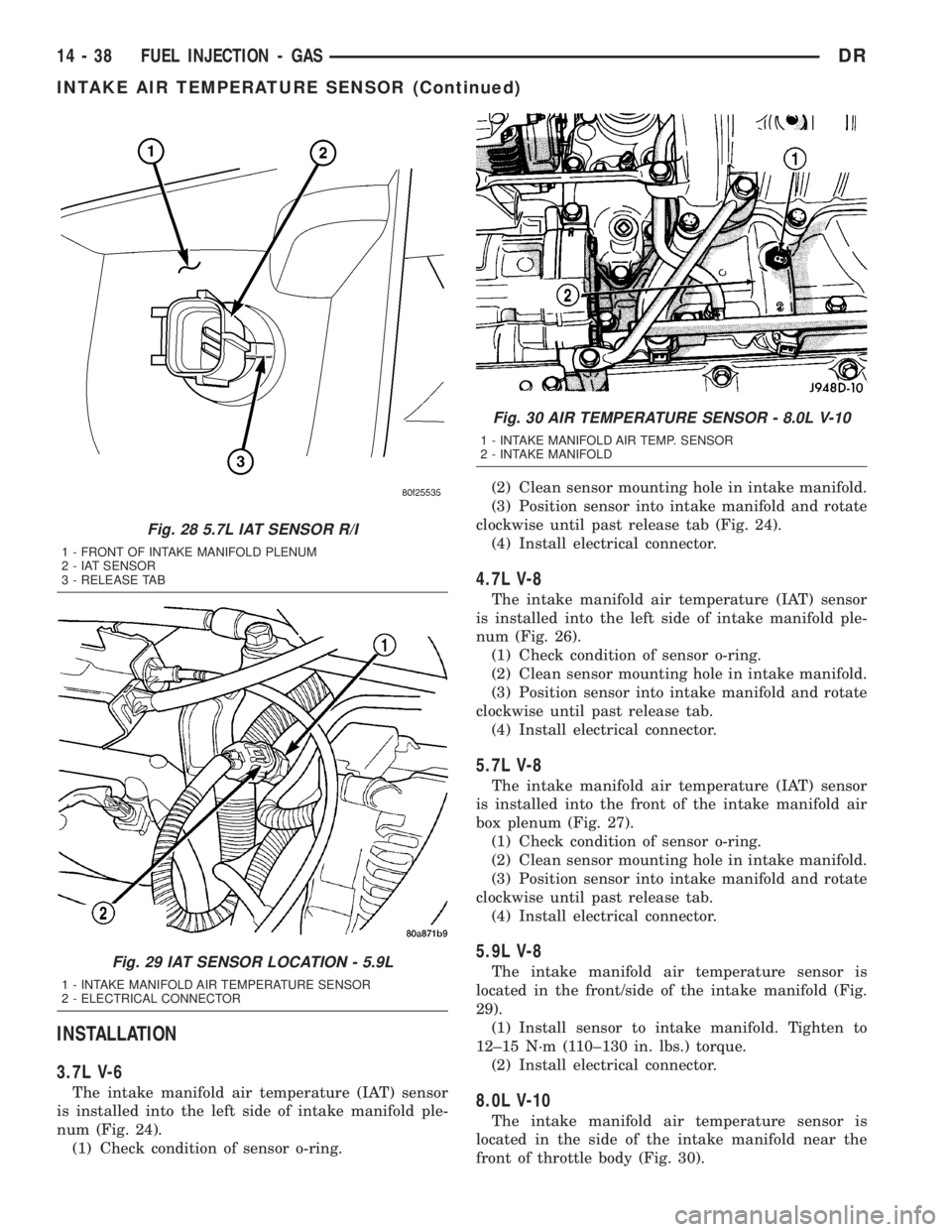
The intake manifold air temperature sensor is
located in the front/side of the intake manifold (Fig.
29).
(1) Install sensor to intake manifold. Tighten to
12±15 N´m (110±130 in. lbs.) torque.
(2) Install electrical connector.
8.0L V-10
The intake manifold air temperature sensor is
located in the side of the intake manifold near the
front of throttle body (Fig. 30).
Fig. 28 5.7L IAT SENSOR R/I
1 - FRONT OF INTAKE MANIFOLD PLENUM
2 - IAT SENSOR
3 - RELEASE TAB
Fig. 29 IAT SENSOR LOCATION - 5.9L
1 - INTAKE MANIFOLD AIR TEMPERATURE SENSOR
2 - ELECTRICAL CONNECTOR
Fig. 30 AIR TEMPERATURE SENSOR - 8.0L V-10
1 - INTAKE MANIFOLD AIR TEMP. SENSOR
2 - INTAKE MANIFOLD
14 - 38 FUEL INJECTION - GASDR
INTAKE AIR TEMPERATURE SENSOR (Continued)
Page 1736 of 2895
(1) Install sensor to intake manifold. Tighten to
12±15 N´m (110±130 in. lbs.) torque.
(2) Install electrical connector.
MAP SENSOR
DESCRIPTION
3.7L V-6
The Manifold Absolute Pressure (MAP) sensor is
mounted into the front of the intake manifold with 2
screws.
4.7L V-8
The Manifold Absolute Pressure (MAP) sensor is
mounted into the front of the intake manifold with 2
screws.
5.7L V-8
The Manifold Absolute Pressure (MAP) sensor is
mounted to the front of the intake manifold air ple-
num box.
5.9L V-8
The Manifold Absolute Pressure (MAP) sensor is
mounted to the front of the throttle body with 2
screws.
8.0L V-10
The Manifold Absolute Pressure (MAP) sensor is
mounted into the right side of the intake manifold.
OPERATION
The MAP sensor is used as an input to the Power-
train Control Module (PCM). It contains a silicon
based sensing unit to provide data on the manifold
vacuum that draws the air/fuel mixture into the com-
bustion chamber. The PCM requires this information
to determine injector pulse width and spark advance.
When manifold absolute pressure (MAP) equals
Barometric pressure, the pulse width will be at max-
imum.
A 5 volt reference is supplied from the PCM and
returns a voltage signal to the PCM that reflects
manifold pressure. The zero pressure reading is 0.5V
and full scale is 4.5V. For a pressure swing of 0±15
psi, the voltage changes 4.0V. To operate the sensor,
it is supplied a regulated 4.8 to 5.1 volts. Ground is
provided through the low-noise, sensor return circuit
at the PCM.
The MAP sensor input is the number one contrib-
utor to fuel injector pulse width. The most important
function of the MAP sensor is to determine baromet-
ric pressure. The PCM needs to know if the vehicle is
at sea level or at a higher altitude, because the airdensity changes with altitude. It will also help to cor-
rect for varying barometric pressure. Barometric
pressure and altitude have a direct inverse correla-
tion; as altitude goes up, barometric goes down. At
key-on, the PCM powers up and looks at MAP volt-
age, and based upon the voltage it sees, it knows the
current barometric pressure (relative to altitude).
Once the engine starts, the PCM looks at the voltage
again, continuously every 12 milliseconds, and com-
pares the current voltage to what it was at key-on.
The difference between current voltage and what it
was at key-on, is manifold vacuum.
During key-on (engine not running) the sensor
reads (updates) barometric pressure. A normal range
can be obtained by monitoring a known good sensor.
As the altitude increases, the air becomes thinner
(less oxygen). If a vehicle is started and driven to a
very different altitude than where it was at key-on,
the barometric pressure needs to be updated. Any
time the PCM sees Wide Open Throttle (WOT), based
upon Throttle Position Sensor (TPS) angle and RPM,
it will update barometric pressure in the MAP mem-
ory cell. With periodic updates, the PCM can make
its calculations more effectively.
The PCM uses the MAP sensor input to aid in cal-
culating the following:
²Manifold pressure
²Barometric pressure
²Engine load
²Injector pulse-width
²Spark-advance programs
²Shift-point strategies (certain automatic trans-
missions only)
²Idle speed
²Decel fuel shutoff
The MAP sensor signal is provided from a single
piezoresistive element located in the center of a dia-
phragm. The element and diaphragm are both made
of silicone. As manifold pressure changes, the dia-
phragm moves causing the element to deflect, which
stresses the silicone. When silicone is exposed to
stress, its resistance changes. As manifold vacuum
increases, the MAP sensor input voltage decreases
proportionally. The sensor also contains electronics
that condition the signal and provide temperature
compensation.
The PCM recognizes a decrease in manifold pres-
sure by monitoring a decrease in voltage from the
reading stored in the barometric pressure memory
cell. The MAP sensor is a linear sensor; meaning as
pressure changes, voltage changes proportionately.
The range of voltage output from the sensor is usu-
ally between 4.6 volts at sea level to as low as 0.3
volts at 26 in. of Hg. Barometric pressure is the pres-
sure exerted by the atmosphere upon an object. At
sea level on a standard day, no storm, barometric
DRFUEL INJECTION - GAS 14 - 39
INTAKE AIR TEMPERATURE SENSOR (Continued)
Page 1739 of 2895
INSTALLATION
3.7L V-6
The Manifold Absolute Pressure (MAP) sensor is
mounted into the front of the intake manifold (Fig.
31). An o-ring is used to seal the sensor to the intake
manifold (Fig. 32).
(1) Clean MAP sensor mounting hole at intake
manifold.
(2) Check MAP sensor o-ring seal for cuts or tears.
(3) Position sensor into manifold.(4) Install MAP sensor mounting bolts (screws).
Refer to Torque Specifications.
(5) Connect electrical connector.
4.7L V-8
The MAP sensor is located on the front of the
intake manifold (Fig. 33). An o-ring seals the sensor
to the intake manifold (Fig. 32).
(1) Clean MAP sensor mounting hole at intake
manifold.
(2) Check MAP sensor o-ring seal for cuts or tears.
(3) Position sensor into manifold.
(4) Install MAP sensor mounting bolts (screws).
Refer to Torque Specifications.
(5) Connect electrical connector.
5.7L V-8
The Manifold Absolute Pressure (MAP) sensor is
mounted to the front of the intake manifold air ple-
num box (Fig. 34).
(1) Clean MAP sensor mounting hole at intake
manifold.
(2) Check MAP sensor o-ring seal for cuts or tears.
(3) Position sensor into manifold.
(4) Rotate sensor 1/4 turn clockwise for installa-
tion.
(5) Connect electrical connector.
5.9L V-8
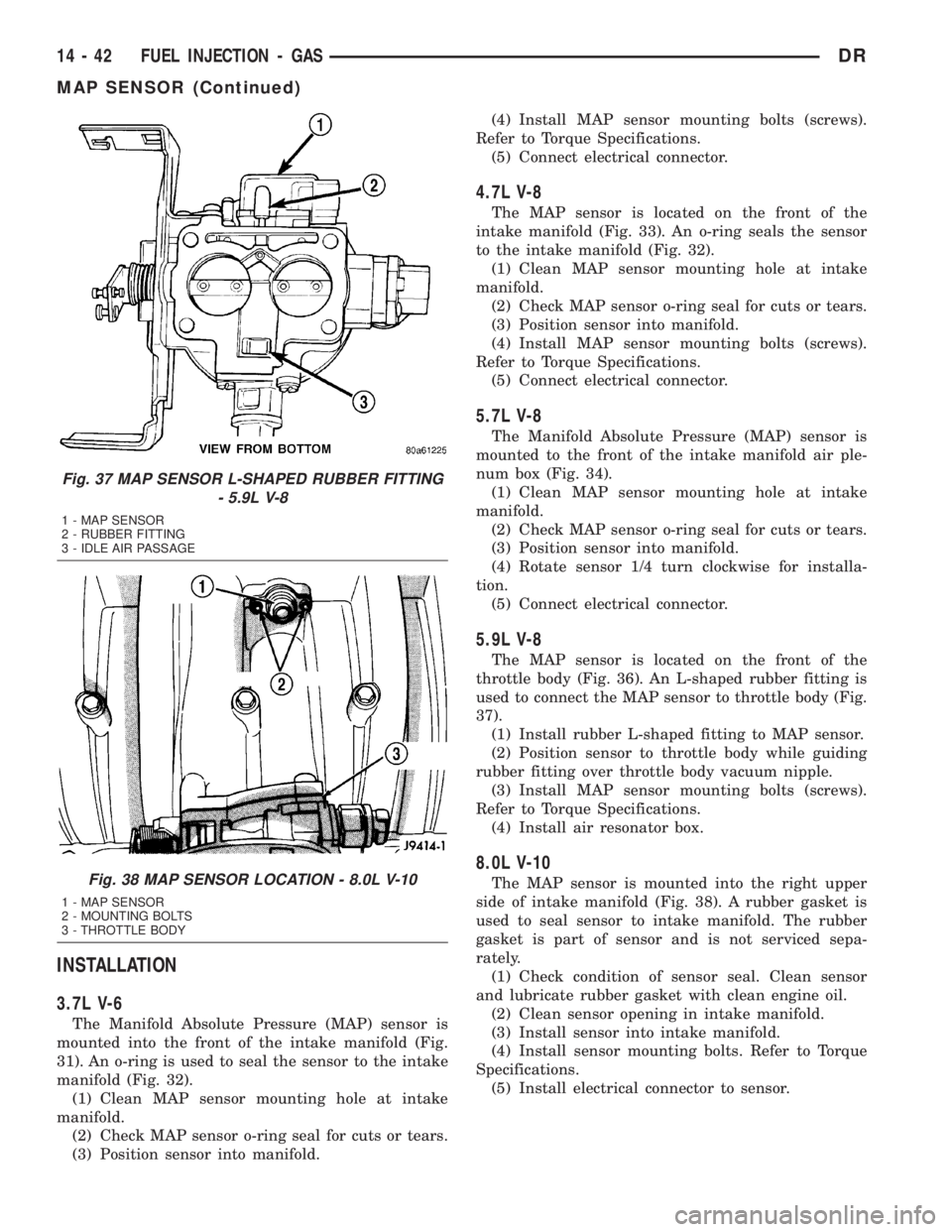
The MAP sensor is located on the front of the
throttle body (Fig. 36). An L-shaped rubber fitting is
used to connect the MAP sensor to throttle body (Fig.
37).
(1) Install rubber L-shaped fitting to MAP sensor.
(2) Position sensor to throttle body while guiding
rubber fitting over throttle body vacuum nipple.
(3) Install MAP sensor mounting bolts (screws).
Refer to Torque Specifications.
(4) Install air resonator box.
8.0L V-10
The MAP sensor is mounted into the right upper
side of intake manifold (Fig. 38). A rubber gasket is
used to seal sensor to intake manifold. The rubber
gasket is part of sensor and is not serviced sepa-
rately.
(1) Check condition of sensor seal. Clean sensor
and lubricate rubber gasket with clean engine oil.
(2) Clean sensor opening in intake manifold.
(3) Install sensor into intake manifold.
(4) Install sensor mounting bolts. Refer to Torque
Specifications.
(5) Install electrical connector to sensor.
Fig. 37 MAP SENSOR L-SHAPED RUBBER FITTING
- 5.9L V-8
1 - MAP SENSOR
2 - RUBBER FITTING
3 - IDLE AIR PASSAGE
Fig. 38 MAP SENSOR LOCATION - 8.0L V-10
1 - MAP SENSOR
2 - MOUNTING BOLTS
3 - THROTTLE BODY
14 - 42 FUEL INJECTION - GASDR
MAP SENSOR (Continued)
Page 1742 of 2895
INSTALLATION
Threads of new oxygen sensors are factory coated
with anti-seize compound to aid in removal.DO
NOT add any additional anti-seize compound to
threads of a new oxygen sensor.
(1) Install O2S sensor. Tighten to 30 N´m (22 ft.
lbs.) torque.
(2) Connect O2S sensor wire connector.
(3) Lower vehicle.
THROTTLE BODY
DESCRIPTION
The throttle body is located on the intake manifold.
Fuel does not enter the intake manifold through the
throttle body. Fuel is sprayed into the manifold by
the fuel injectors.
OPERATION
Filtered air from the air cleaner enters the intake
manifold through the throttle body. The throttle body
contains an air control passage controlled by an Idle
Air Control (IAC) motor. The air control passage is
used to supply air for idle conditions. A throttle valve
(plate) is used to supply air for above idle conditions.
5.7L V-8 Engine:
The throttle body on the 5.7L engine is an electri-
cally controlled unit. A mechanical cable is not used
to connect the throttle body to the accelerator pedal.
The Accelerator Pedal Position Sensor (APPS) along
with inputs from other sensors sets the throttle blade
to pre-determined positions.
Except 5.7L V-8 Engine:
Certain sensors are attached to the throttle body.
The accelerator pedal cable, speed control cable and
transmission control cable (when equipped) are con-
nected to the throttle body linkage arm.
A (factory adjusted) set screw is used to mechani-
cally limit the position of the throttle body throttle
plate.Never attempt to adjust the engine idle
speed using this screw.All idle speed functions are
controlled by the PCM.
REMOVAL
3.7L V-6
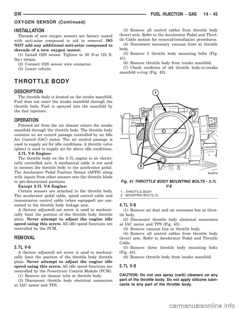
A (factory adjusted) set screw is used to mechani-
cally limit the position of the throttle body throttle
plate.Never attempt to adjust the engine idle
speed using this screw.All idle speed functions are
controlled by the Powertrain Control Module (PCM).
(1) Remove air cleaner tube at throttle body.
(2) Disconnect throttle body electrical connectors
at IAC motor and TPS.(3) Remove all control cables from throttle body
(lever) arm. Refer to the Accelerator Pedal and Throt-
tle Cable section for removal/installation procedures.
(4) Disconnect necessary vacuum lines at throttle
body.
(5) Remove 3 throttle body mounting bolts (Fig.
41).
(6) Remove throttle body from intake manifold.
(7) Check condition of old throttle body-to-intake
manifold o-ring (Fig. 42).
4.7L V-8
(1) Remove air duct and air resonator box at throt-
tle body.
(2) Disconnect throttle body electrical connectors
at IAC motor and TPS (Fig. 43).
(3) Remove vacuum line at throttle body.
(4) Remove all control cables from throttle body
(lever) arm. Refer to Accelerator Pedal and Throttle
Cable.
(5) Remove three throttle body mounting bolts
(Fig. 43).
(6) Remove throttle body from intake manifold.
5.7L V-8
CAUTION: Do not use spray (carb) cleaners on any
part of the throttle body. Do not apply silicone lubri-
cants to any part of the throttle body.
Fig. 41 THROTTLE BODY MOUNTING BOLTS - 3.7L
V-6
1 - THROTTLE BODY
2 - MOUNTING BOLTS (3)
DRFUEL INJECTION - GAS 14 - 45
OXYGEN SENSOR (Continued)
Page 1743 of 2895
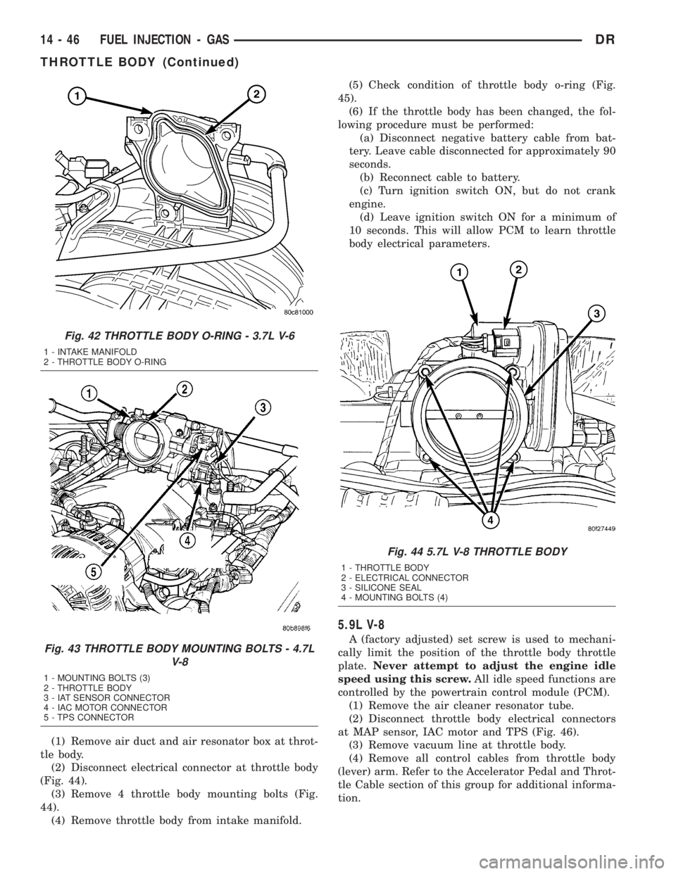
(1) Remove air duct and air resonator box at throt-
tle body.
(2) Disconnect electrical connector at throttle body
(Fig. 44).
(3) Remove 4 throttle body mounting bolts (Fig.
44).
(4) Remove throttle body from intake manifold.(5) Check condition of throttle body o-ring (Fig.
45).
(6) If the throttle body has been changed, the fol-
lowing procedure must be performed:
(a) Disconnect negative battery cable from bat-
tery. Leave cable disconnected for approximately 90
seconds.
(b) Reconnect cable to battery.
(c) Turn ignition switch ON, but do not crank
engine.
(d) Leave ignition switch ON for a minimum of
10 seconds. This will allow PCM to learn throttle
body electrical parameters.
5.9L V-8
A (factory adjusted) set screw is used to mechani-
cally limit the position of the throttle body throttle
plate.Never attempt to adjust the engine idle
speed using this screw.All idle speed functions are
controlled by the powertrain control module (PCM).
(1) Remove the air cleaner resonator tube.
(2) Disconnect throttle body electrical connectors
at MAP sensor, IAC motor and TPS (Fig. 46).
(3) Remove vacuum line at throttle body.
(4) Remove all control cables from throttle body
(lever) arm. Refer to the Accelerator Pedal and Throt-
tle Cable section of this group for additional informa-
tion.
Fig. 42 THROTTLE BODY O-RING - 3.7L V-6
1 - INTAKE MANIFOLD
2 - THROTTLE BODY O-RING
Fig. 43 THROTTLE BODY MOUNTING BOLTS - 4.7L
V-8
1 - MOUNTING BOLTS (3)
2 - THROTTLE BODY
3 - IAT SENSOR CONNECTOR
4 - IAC MOTOR CONNECTOR
5 - TPS CONNECTOR
Fig. 44 5.7L V-8 THROTTLE BODY
1 - THROTTLE BODY
2 - ELECTRICAL CONNECTOR
3 - SILICONE SEAL
4 - MOUNTING BOLTS (4)
14 - 46 FUEL INJECTION - GASDR
THROTTLE BODY (Continued)
Page 1744 of 2895
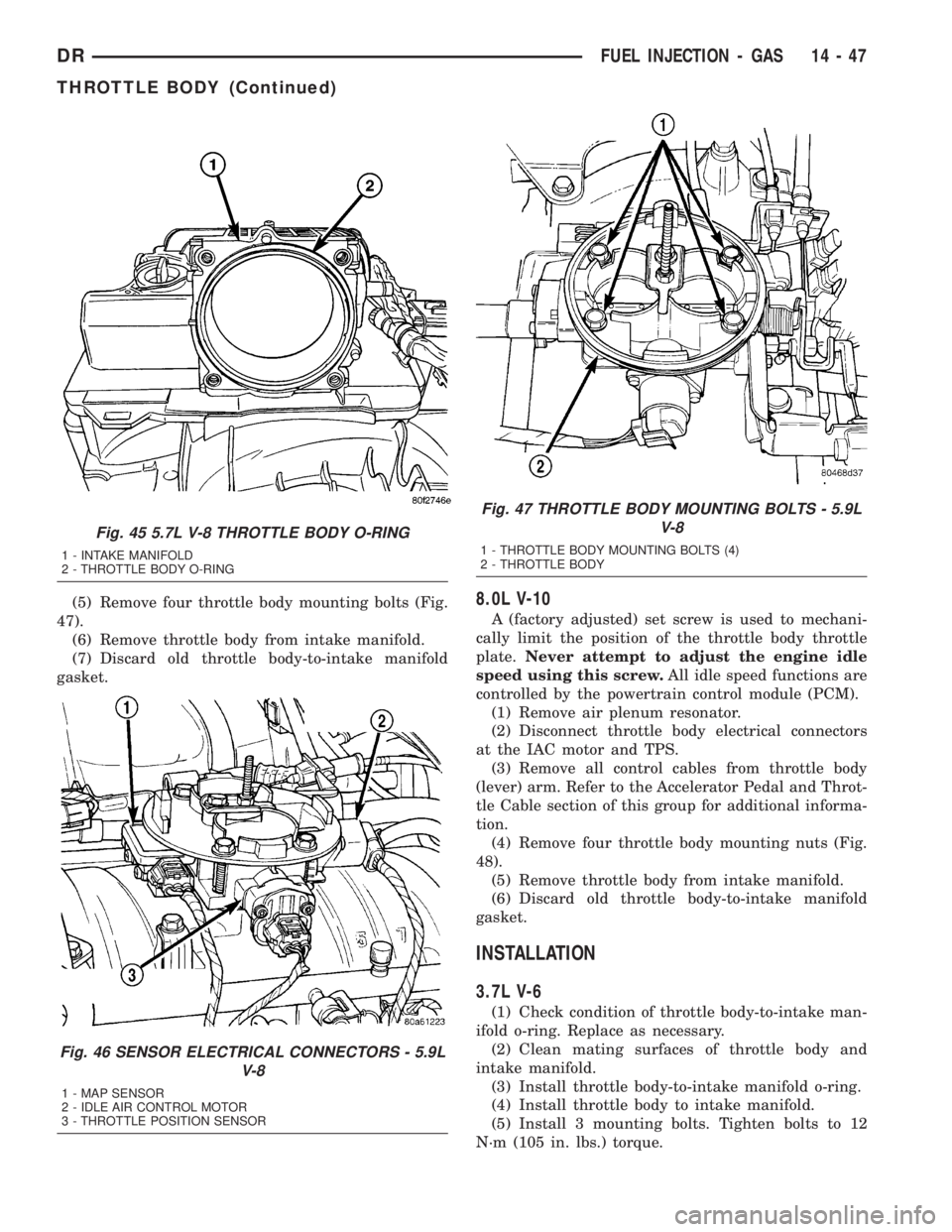
(5) Remove four throttle body mounting bolts (Fig.
47).
(6) Remove throttle body from intake manifold.
(7) Discard old throttle body-to-intake manifold
gasket.8.0L V-10
A (factory adjusted) set screw is used to mechani-
cally limit the position of the throttle body throttle
plate.Never attempt to adjust the engine idle
speed using this screw.All idle speed functions are
controlled by the powertrain control module (PCM).
(1) Remove air plenum resonator.
(2) Disconnect throttle body electrical connectors
at the IAC motor and TPS.
(3) Remove all control cables from throttle body
(lever) arm. Refer to the Accelerator Pedal and Throt-
tle Cable section of this group for additional informa-
tion.
(4) Remove four throttle body mounting nuts (Fig.
48).
(5) Remove throttle body from intake manifold.
(6) Discard old throttle body-to-intake manifold
gasket.
INSTALLATION
3.7L V-6
(1) Check condition of throttle body-to-intake man-
ifold o-ring. Replace as necessary.
(2) Clean mating surfaces of throttle body and
intake manifold.
(3) Install throttle body-to-intake manifold o-ring.
(4) Install throttle body to intake manifold.
(5) Install 3 mounting bolts. Tighten bolts to 12
N´m (105 in. lbs.) torque.
Fig. 45 5.7L V-8 THROTTLE BODY O-RING
1 - INTAKE MANIFOLD
2 - THROTTLE BODY O-RING
Fig. 46 SENSOR ELECTRICAL CONNECTORS - 5.9L
V-8
1 - MAP SENSOR
2 - IDLE AIR CONTROL MOTOR
3 - THROTTLE POSITION SENSOR
Fig. 47 THROTTLE BODY MOUNTING BOLTS - 5.9L
V-8
1 - THROTTLE BODY MOUNTING BOLTS (4)
2 - THROTTLE BODY
DRFUEL INJECTION - GAS 14 - 47
THROTTLE BODY (Continued)
Page 1747 of 2895
5.7L V-8
The Throttle Control Cable on the 5.7L V-8 engine
connects the accelerator pedal to the Accelerator
Pedal Position Sensor (APPS). A separate mechanical
cable is not routed to the throttle body.
CAUTION: Be careful not to damage or kink cable
core wire (within cable sheathing) while servicing
accelerator pedal, cables or APPS.
(1) From inside vehicle, hold up accelerator pedal.
Remove plastic cable retainer and throttle cable core
wire from upper end of pedal arm (Fig. 1). The plas-
tic cable retainer snaps into pedal arm.
(2) Remove cable core wire at pedal arm.
(3) Remove APPS. Refer to Accelerator Pedal Posi-
tion Sensor (APPS) Removal / Installation.
(4) From inside vehicle, remove cable clip (Fig. 1).
(5) Remove cable housing from dash panel and
pull cable into engine compartment.
(6) Remove cable housing at APPS bracket by
pressing on release tab with a small screwdriver.To
prevent cable housing breakage, press on tab
only enough to release cable from APPS
bracket.
5.9L V-8
CAUTION: Be careful not to damage or kink cable
core wire (within cable sheathing) while servicing
accelerator pedal or cables.
(1) From inside vehicle, hold up accelerator pedal.
Remove plastic cable retainer and throttle cable core
wire from upper end of pedal arm (Fig. 1). The plas-
tic cable retainer snaps into pedal arm.
(2) Remove cable core wire at pedal arm.
(3) Remove air resonator at throttle body.
(4) From inside vehicle, remove cable clip (Fig. 1).
(5) Remove cable housing from dash panel and
pull cable into engine compartment.
(6) Disconnect cable from routing/holddown clip.
(7) Slip cable end rearward from pin on throttle
body (Fig. 53).
(8) Remove cable housing at throttle body mount-
ing bracket by pressing on release tab with a small
screwdriver (Fig. 54).To prevent cable housing
breakage, press on tab only enough to release
cable from bracket.Lift cable housing straight up
from bracket while pressing on release tab. Remove
throttle cable from vehicle.
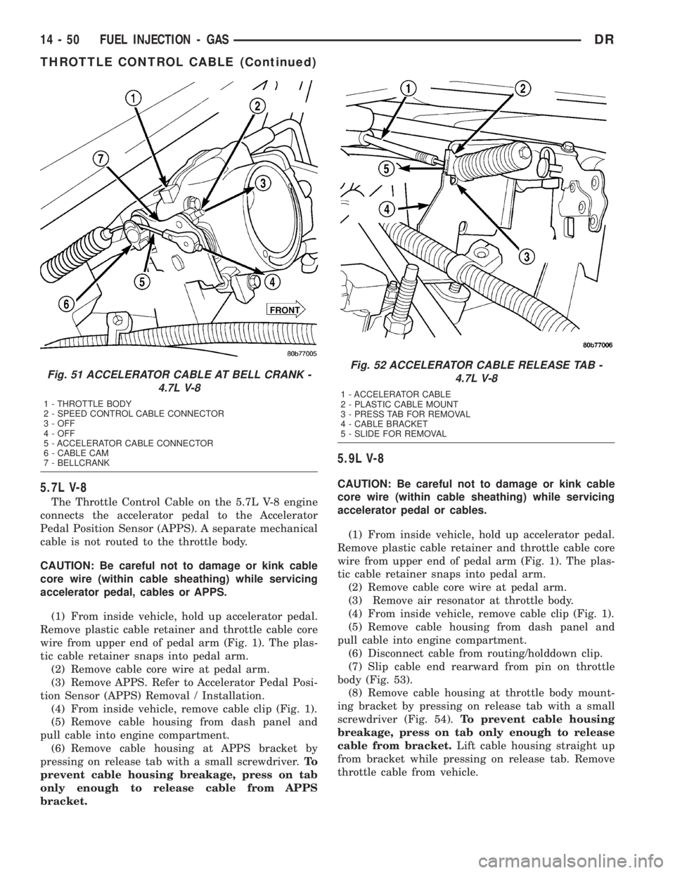
Fig. 51 ACCELERATOR CABLE AT BELL CRANK -
4.7L V-8
1 - THROTTLE BODY
2 - SPEED CONTROL CABLE CONNECTOR
3 - OFF
4 - OFF
5 - ACCELERATOR CABLE CONNECTOR
6 - CABLE CAM
7 - BELLCRANK
Fig. 52 ACCELERATOR CABLE RELEASE TAB -
4.7L V-8
1 - ACCELERATOR CABLE
2 - PLASTIC CABLE MOUNT
3 - PRESS TAB FOR REMOVAL
4 - CABLE BRACKET
5 - SLIDE FOR REMOVAL
14 - 50 FUEL INJECTION - GASDR
THROTTLE CONTROL CABLE (Continued)
Page 1749 of 2895
(4) From inside vehicle, install metal clip holding
cable to dashpanel (Fig. 1).
(5) From inside vehicle, slide throttle cable core
wire into opening (slot) in top of pedal arm.
(6) Push plastic cable retainer (clip) into pedal arm
opening until it snaps in place.
(7) Install air resonator tube to throttle body.
(8) Before starting engine, operate accelerator
pedal to check for any binding.
4.7L V-8
(1) Slide accelerator cable plastic mount into
bracket. Continue sliding until tab (Fig. 52) is
aligned to hole in mounting bracket.
(2) Route accelerator cable over top of cable cam.
(3) Connect cable end to throttle body bellcrank
pin (snaps on rearward).
(4) Slide rubber grommet away from plastic cable
housing.
(5) Install rubber grommet into dash panel until
seated.
(6) Push cable housing into rubber grommet and
through opening in dash panel.
(7) From inside vehicle, install clip holding cable
to dashpanel (Fig. 1).
(8) From inside vehicle, slide throttle cable core
wire into opening in top of pedal arm.
(9) Push cable retainer (clip) into pedal arm open-
ing until it snaps in place.
(10) Snap cable into dashpanel routing clip.
(11) Install air resonator tube to throttle body.
(12) Before starting engine, operate accelerator
pedal to check for any binding.
5.7L V-8
(1) Attach cable to Accelerator Pedal Position Sen-
sor (APPS). Refer to APPS Removal / Installation.
(2) Push cable housing into rubber grommet and
through opening in dash panel.
(3) From inside vehicle, install clip holding cable
to dashpanel (Fig. 1).
(4) From inside vehicle, slide throttle cable core
wire into opening in top of pedal arm.
(5) Push cable retainer (clip) into pedal arm open-
ing until it snaps in place.
(6) Before starting engine, operate accelerator
pedal to check for any binding.
(7) If necessary, use DRB IIItScan Tool to erase
any APPS Diagnostic Trouble Codes (DTC's) from
PCM.
5.9L V-8
(1) Slide accelerator cable plastic mount into throt-
tle body mounting bracket. Continue sliding until
release tab (Fig. 54) is aligned to hole in mounting
bracket.(2) Hold throttle in wide open position. While held
in this position, slide throttle cable pin into throttle
body bellcrank.
(3) Push cable housing into rubber grommet and
through opening in dash panel.
(4) From inside vehicle, install metal clip holding
cable to dashpanel (Fig. 1).
(5) From inside vehicle, slide throttle cable core
wire into opening (slot) in top of pedal arm.
(6) Push plastic cable retainer (clip) into pedal arm
opening until it snaps in place.
(7) Install air resonator tube to throttle body.
(8) Before starting engine, operate accelerator
pedal to check for any binding.
8.0L V-10
(1) Connect cable end socket to throttle body lever
ball (snaps on) (Fig. 55).
(2) Connect cable to throttle body mounting
bracket (push down and lock)
(3) Install the remaining cable housing end into
and through the dash panel opening (snaps into posi-
tion). The two plastic pinch tabs (Fig. 1) should lock
the cable to dash panel.
(4) From inside the vehicle, hold up the accelera-
tor pedal. Install the throttle cable core wire and
plastic cable retainer into and through the upper end
of the pedal arm (the plastic retainer is snapped into
the pedal arm). When installing the plastic retainer
to the accelerator pedal arm, note the index tab on
the pedal arm (Fig. 1). Align the index slot on the
plastic cable retainer to this index tab.
(5) Install air resonator tube to throttle body.
(6) Before starting engine, operate accelerator
pedal to check for any binding.
THROTTLE POSITION SENSOR
DESCRIPTION
The 3-wire Throttle Position Sensor (TPS) is
mounted on the throttle body and is connected to the
throttle blade shaft.
The 5.7L V-8 engine does not use a separate TPS
on the throttle body.
OPERATION
The 5.7L V-8 engine does not use a separate Throt-
tle Position Sensor (TPS) on the throttle body.
The 3±wire TPS provides the Powertrain Control
Module (PCM) with an input signal (voltage) that
represents the throttle blade position of the throttle
body. The sensor is connected to the throttle blade
shaft. As the position of the throttle blade changes,
the output voltage of the TPS changes.
14 - 52 FUEL INJECTION - GASDR
THROTTLE CONTROL CABLE (Continued)
Page 1750 of 2895
The PCM supplies approximately 5 volts to the
TPS. The TPS output voltage (input signal to the
PCM) represents the throttle blade position. The
PCM receives an input signal voltage from the TPS.
This will vary in an approximate range of from .26
volts at minimum throttle opening (idle), to 4.49 volts
at wide open throttle. Along with inputs from other
sensors, the PCM uses the TPS input to determine
current engine operating conditions. In response to
engine operating conditions, the PCM will adjust fuel
injector pulse width and ignition timing.
The PCM needs to identify the actions and position
of the throttle blade at all times. This information is
needed to assist in performing the following calcula-
tions:
²Ignition timing advance
²Fuel injection pulse-width
²Idle (learned value or minimum TPS)
²Off-idle (0.06 volt)
²Wide Open Throttle (WOT) open loop (2.608
volts above learned idle voltage)
²Deceleration fuel lean out
²Fuel cutoff during cranking at WOT (2.608 volts
above learned idle voltage)
²A/C WOT cutoff (certain automatic transmis-
sions only)
REMOVAL
3.7L V6
The Throttle Position Sensor (TPS) is mounted to
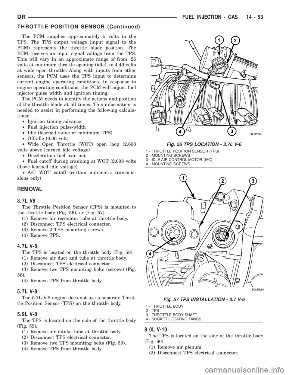
the throttle body (Fig. 56), or (Fig. 57).
(1) Remove air resonator tube at throttle body.
(2) Disconnect TPS electrical connector.
(3) Remove 2 TPS mounting screws.
(4) Remove TPS.
4.7L V-8
The TPS is located on the throttle body (Fig. 58).
(1) Remove air duct and tube at throttle body.
(2) Disconnect TPS electrical connector.
(3) Remove two TPS mounting bolts (screws) (Fig.
58).
(4) Remove TPS from throttle body.
5.7L V-8
The 5.7L V-8 engine does not use a separate Throt-
tle Position Sensor (TPS) on the throttle body.
5.9L V-8
The TPS is located on the side of the throttle body
(Fig. 59).
(1) Remove air intake tube at throttle body.
(2) Disconnect TPS electrical connector.
(3) Remove two TPS mounting bolts (Fig. 59).
(4) Remove TPS from throttle body.
8.0L V-10
The TPS is located on the side of the throttle body
(Fig. 60).
(1) Remove air plenum.
(2) Disconnect TPS electrical connector.
Fig. 56 TPS LOCATION - 3.7L V-6
1 - THROTTLE POSITION SENSOR (TPS)
2 - MOUNTING SCREWS
3 - IDLE AIR CONTROL MOTOR (IAC)
4 - MOUNTING SCREWS
Fig. 57 TPS INSTALLATION - 3.7 V-6
1 - THROTTLE BODY
2 - TPS
3 - THROTTLE BODY SHAFT
4 - SOCKET LOCATING TANGS
DRFUEL INJECTION - GAS 14 - 53
THROTTLE POSITION SENSOR (Continued)
Page 1751 of 2895
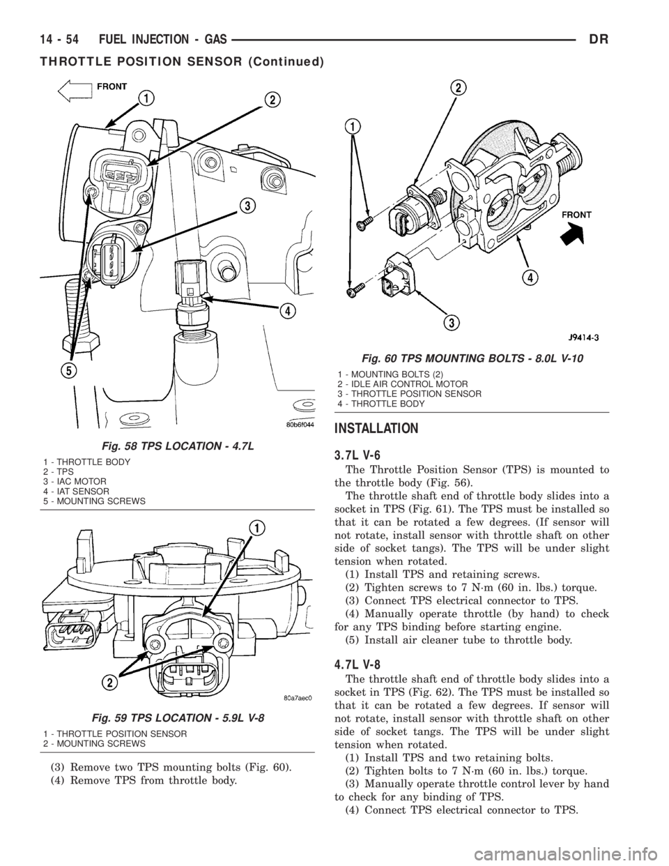
(3) Remove two TPS mounting bolts (Fig. 60).
(4) Remove TPS from throttle body.
INSTALLATION
3.7L V-6
The Throttle Position Sensor (TPS) is mounted to
the throttle body (Fig. 56).
The throttle shaft end of throttle body slides into a
socket in TPS (Fig. 61). The TPS must be installed so
that it can be rotated a few degrees. (If sensor will
not rotate, install sensor with throttle shaft on other
side of socket tangs). The TPS will be under slight
tension when rotated.
(1) Install TPS and retaining screws.
(2) Tighten screws to 7 N´m (60 in. lbs.) torque.
(3) Connect TPS electrical connector to TPS.
(4) Manually operate throttle (by hand) to check
for any TPS binding before starting engine.
(5) Install air cleaner tube to throttle body.
4.7L V-8
The throttle shaft end of throttle body slides into a
socket in TPS (Fig. 62). The TPS must be installed so
that it can be rotated a few degrees. If sensor will
not rotate, install sensor with throttle shaft on other
side of socket tangs. The TPS will be under slight
tension when rotated.
(1) Install TPS and two retaining bolts.
(2) Tighten bolts to 7 N´m (60 in. lbs.) torque.
(3) Manually operate throttle control lever by hand
to check for any binding of TPS.
(4) Connect TPS electrical connector to TPS.
Fig. 58 TPS LOCATION - 4.7L
1 - THROTTLE BODY
2 - TPS
3 - IAC MOTOR
4 - IAT SENSOR
5 - MOUNTING SCREWS
Fig. 59 TPS LOCATION - 5.9L V-8
1 - THROTTLE POSITION SENSOR
2 - MOUNTING SCREWS
Fig. 60 TPS MOUNTING BOLTS - 8.0L V-10
1 - MOUNTING BOLTS (2)
2 - IDLE AIR CONTROL MOTOR
3 - THROTTLE POSITION SENSOR
4 - THROTTLE BODY
14 - 54 FUEL INJECTION - GASDR
THROTTLE POSITION SENSOR (Continued)