Oss DODGE RAM 2003 Service Repair Manual
[x] Cancel search | Manufacturer: DODGE, Model Year: 2003, Model line: RAM, Model: DODGE RAM 2003Pages: 2895, PDF Size: 83.15 MB
Page 2 of 2895
INTRODUCTION
TABLE OF CONTENTS
page page
VEHICLE SAFETY CERTIFICATION LABEL
DESCRIPTION..........................1
VEHICLE IDENTIFICATION NUMBER
DESCRIPTION..........................2
VEHICLE EMISSION CONTROL INFORMATION
(VECI)
DESCRIPTION..........................3
BODY CODE PLATE
DESCRIPTION..........................4
INTERNATIONAL VEHICLE CONTROL &
DISPLAY SYMBOLS
DESCRIPTION - INTERNATIONAL SYMBOLS . . . 6FASTENER IDENTIFICATION
DESCRIPTION..........................6
FASTENER USAGE
DESCRIPTION - FASTENER USAGE.........9
THREADED HOLE REPAIR
DESCRIPTION - THREADED HOLE REPAIR....9
METRIC SYSTEM
DESCRIPTION..........................9
TORQUE REFERENCES
DESCRIPTION.........................11
VEHICLE SAFETY
CERTIFICATION LABEL
DESCRIPTION
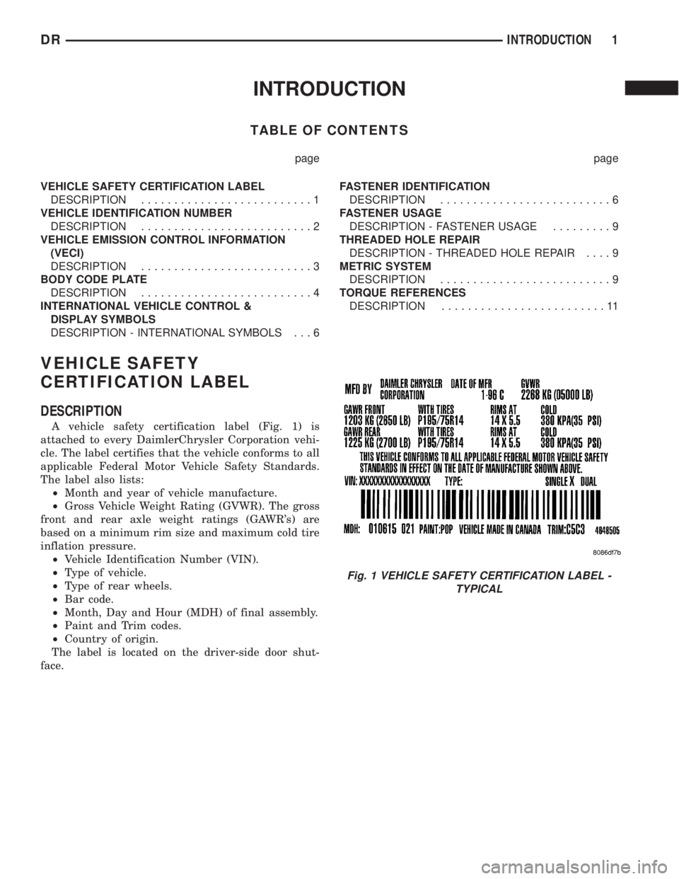
A vehicle safety certification label (Fig. 1) is
attached to every DaimlerChrysler Corporation vehi-
cle. The label certifies that the vehicle conforms to all
applicable Federal Motor Vehicle Safety Standards.
The label also lists:
²Month and year of vehicle manufacture.
²Gross Vehicle Weight Rating (GVWR). The gross
front and rear axle weight ratings (GAWR's) are
based on a minimum rim size and maximum cold tire
inflation pressure.
²Vehicle Identification Number (VIN).
²Type of vehicle.
²Type of rear wheels.
²Bar code.
²Month, Day and Hour (MDH) of final assembly.
²Paint and Trim codes.
²Country of origin.
The label is located on the driver-side door shut-
face.
Fig. 1 VEHICLE SAFETY CERTIFICATION LABEL -
TYPICAL
DRINTRODUCTION 1
Page 3 of 2895
VEHICLE IDENTIFICATION
NUMBER
DESCRIPTION
VIN CODING/LOCATIONS
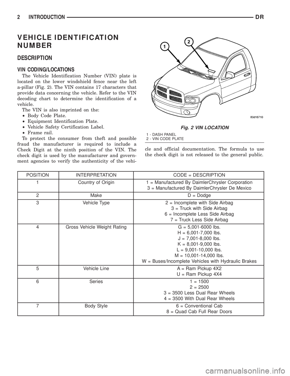
The Vehicle Identification Number (VIN) plate is
located on the lower windshield fence near the left
a-pillar (Fig. 2). The VIN contains 17 characters that
provide data concerning the vehicle. Refer to the VIN
decoding chart to determine the identification of a
vehicle.
The VIN is also imprinted on the:
²Body Code Plate.
²Equipment Identification Plate.
²Vehicle Safety Certification Label.
²Frame rail.
To protect the consumer from theft and possible
fraud the manufacturer is required to include a
Check Digit at the ninth position of the VIN. The
check digit is used by the manufacturer and govern-
ment agencies to verify the authenticity of the vehi-cle and official documentation. The formula to use
the check digit is not released to the general public.
POSITION INTERPRETATION CODE = DESCRIPTION
1 Country of Origin 1 = Manufactured By DaimlerChrysler Corporation
3 = Manufactured By DaimlerChrysler De Mexico
2 Make D = Dodge
3 Vehicle Type 2 = Incomplete with Side Airbag
3 = Truck with Side Airbag
6 = Incomplete Less Side Airbag
7 = Truck Less Side Airbag
4 Gross Vehicle Weight Rating G = 5,001-6000 lbs.
H = 6,001-7,000 lbs.
J = 7,001-8,000 lbs.
K = 8,001-9,000 lbs.
L = 9,001-10,000 lbs.
M = 10,001-14,000 lbs.
W = Buses/Incomplete Vehicles with Hydraulic Brakes
5 Vehicle Line A = Ram Pickup 4X2
U = Ram Pickup 4X4
6 Series 1 = 1500
2 = 2500
3 = 3500 Less Dual Rear Wheels
4 = 3500 With Dual Rear Wheels
7 Body Style 6 = Conventional Cab
8 = Quad Cab Full Rear Doors
Fig. 2 VIN LOCATION
1 - DASH PANEL
2 - VIN CODE PLATE
2 INTRODUCTIONDR
Page 5 of 2895
BODY CODE PLATE
DESCRIPTION
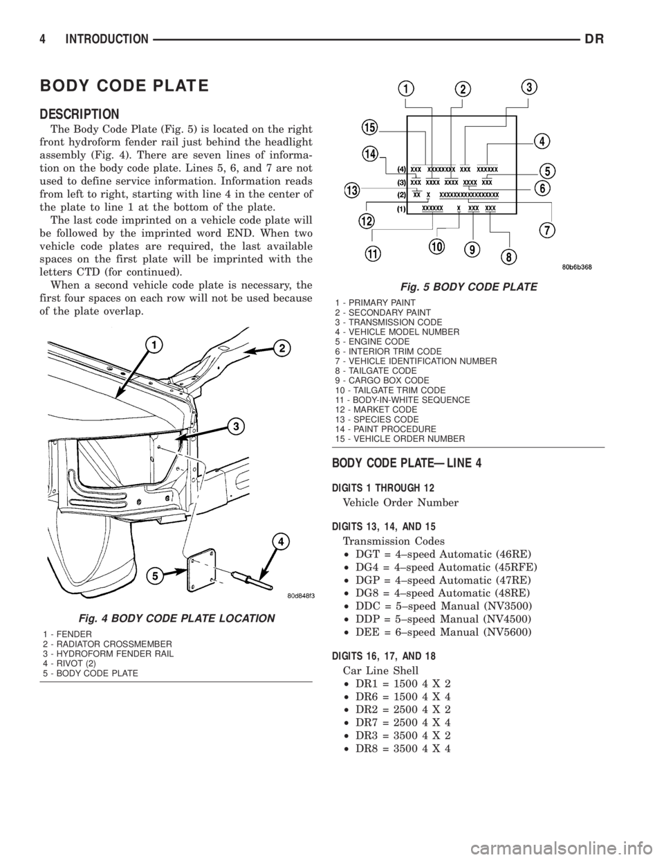
The Body Code Plate (Fig. 5) is located on the right
front hydroform fender rail just behind the headlight
assembly (Fig. 4). There are seven lines of informa-
tion on the body code plate. Lines 5, 6, and 7 are not
used to define service information. Information reads
from left to right, starting with line 4 in the center of
the plate to line 1 at the bottom of the plate.
The last code imprinted on a vehicle code plate will
be followed by the imprinted word END. When two
vehicle code plates are required, the last available
spaces on the first plate will be imprinted with the
letters CTD (for continued).
When a second vehicle code plate is necessary, the
first four spaces on each row will not be used because
of the plate overlap.
BODY CODE PLATEÐLINE 4
DIGITS 1 THROUGH 12
Vehicle Order Number
DIGITS 13, 14, AND 15
Transmission Codes
²DGT = 4±speed Automatic (46RE)
²DG4 = 4±speed Automatic (45RFE)
²DGP = 4±speed Automatic (47RE)
²DG8 = 4±speed Automatic (48RE)
²DDC = 5±speed Manual (NV3500)
²DDP = 5±speed Manual (NV4500)
²DEE = 6±speed Manual (NV5600)
DIGITS 16, 17, AND 18
Car Line Shell
²DR1=15004X2
²DR6=15004X4
²DR2=25004X2
²DR7=25004X4
²DR3=35004X2
²DR8=35004X4
Fig. 4 BODY CODE PLATE LOCATION
1 - FENDER
2 - RADIATOR CROSSMEMBER
3 - HYDROFORM FENDER RAIL
4 - RIVOT (2)
5 - BODY CODE PLATE
Fig. 5 BODY CODE PLATE
1 - PRIMARY PAINT
2 - SECONDARY PAINT
3 - TRANSMISSION CODE
4 - VEHICLE MODEL NUMBER
5 - ENGINE CODE
6 - INTERIOR TRIM CODE
7 - VEHICLE IDENTIFICATION NUMBER
8 - TAILGATE CODE
9 - CARGO BOX CODE
10 - TAILGATE TRIM CODE
11 - BODY-IN-WHITE SEQUENCE
12 - MARKET CODE
13 - SPECIES CODE
14 - PAINT PROCEDURE
15 - VEHICLE ORDER NUMBER
4 INTRODUCTIONDR
Page 26 of 2895
JUMP STARTING
STANDARD PROCEDURE - JUMP STARTING
WARNING: REVIEW ALL SAFETY PRECAUTIONS
AND WARNINGS IN THE BATTERY SYSTEM SEC-
TION OF THE SERVICE MANUAL. (Refer to 8 -
ELECTRICAL/BATTERY SYSTEM/BATTERY - STAN-
DARD PROCEDURE)
²DO NOT JUMP START A FROZEN BATTERY,
PERSONAL INJURY CAN RESULT.
²IF EQUIPPED, DO NOT JUMP START WHEN
MAINTENANCE FREE BATTERY INDICATOR DOT IS
YELLOW OR BRIGHT COLOR.
²DO NOT JUMP START A VEHICLE WHEN THE
BATTERY FLUID IS BELOW THE TOP OF LEAD
PLATES.
²DO NOT ALLOW JUMPER CABLE CLAMPS TO
TOUCH EACH OTHER WHEN CONNECTED TO A
BOOSTER SOURCE.
²DO NOT USE OPEN FLAME NEAR BATTERY.
²REMOVE METALLIC JEWELRY WORN ON
HANDS OR WRISTS TO AVOID INJURY BY ACCI-
DENTAL ARCING OF BATTERY CURRENT.
²WHEN USING A HIGH OUTPUT BOOSTING
DEVICE, DO NOT ALLOW BATTERY VOLTAGE TO
EXCEED 16 VOLTS. REFER TO INSTRUCTIONS
PROVIDED WITH DEVICE BEING USED.
FAILURE TO FOLLOW THESE INSTRUCTIONS MAY
RESULT IN PERSONAL INJURY.
CAUTION: When using another vehicle as a
booster, do not allow vehicles to touch. Electrical
systems can be damaged on either vehicle.
TO JUMP START A DISABLED VEHICLE:
(1) Raise hood on disabled vehicle and visually
inspect engine compartment for:
²Battery cable clamp condition, clean if necessary.
²Frozen battery.
²Yellow or bright color test indicator, if equipped.
²Low battery fluid level.
²Generator drive belt condition and tension.
²Fuel fumes or leakage, correct if necessary.CAUTION: If the cause of starting problem on dis-
abled vehicle is severe, damage to booster vehicle
charging system can result.
(2) When using another vehicle as a booster
source, park the booster vehicle within cable reach.
Turn off all accessories, set the parking brake, place
the automatic transmission in PARK or the manual
transmission in NEUTRAL and turn the ignition
OFF.
(3) On disabled vehicle, place gear selector in park
or neutral and set park brake. Turn off all accesso-
ries.
(4) Connect jumper cables to booster battery. RED
clamp to positive terminal (+). BLACK clamp to neg-
ative terminal (-). DO NOT allow clamps at opposite
end of cables to touch, electrical arc will result.
Review all warnings in this procedure.
(5) On disabled vehicle, connect RED jumper cable
clamp to positive (+) terminal. Connect BLACK
jumper cable clamp to engine ground as close to the
ground cable attaching point as possible.
(6) Start the engine in the vehicle which has the
booster battery, let the engine idle a few minutes,
then start the engine in the vehicle with the dis-
charged battery.
CAUTION: Do not crank starter motor on disabled
vehicle for more than 15 seconds, starter will over-
heat and could fail.
(7) Allow battery in disabled vehicle to charge to
at least 12.4 volts (75% charge) before attempting to
start engine. If engine does not start within 15 sec-
onds, stop cranking engine and allow starter to cool
(15 min.), before cranking again.
DISCONNECT CABLE CLAMPS AS FOLLOWS:
²Disconnect BLACK cable clamp from engine
ground on disabled vehicle.
²When using a Booster vehicle, disconnect
BLACK cable clamp from battery negative terminal.
Disconnect RED cable clamp from battery positive
terminal.
²Disconnect RED cable clamp from battery posi-
tive terminal on disabled vehicle.
DRLUBRICATION & MAINTENANCE 0 - 13
Page 27 of 2895
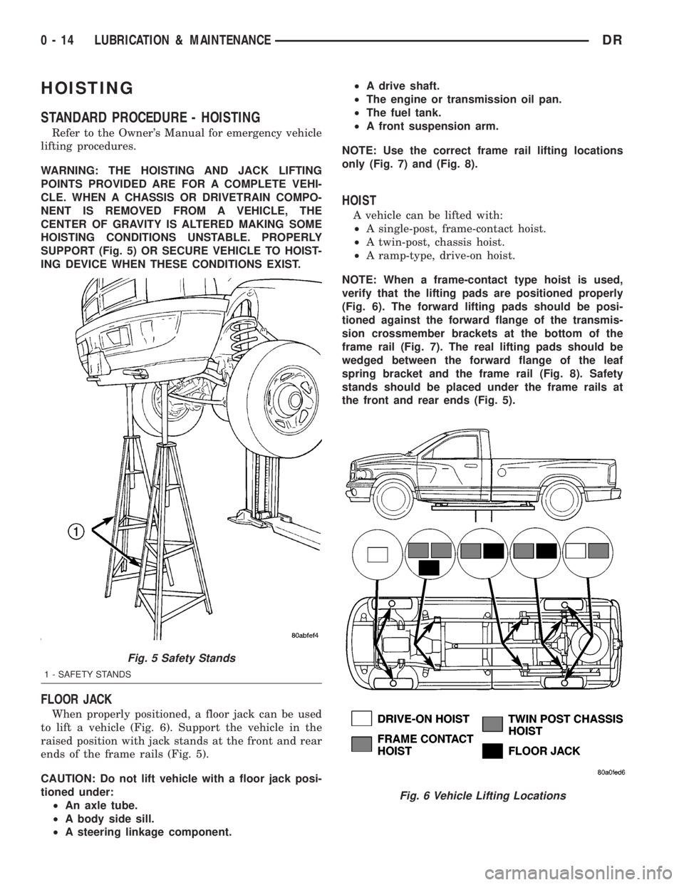
HOISTING
STANDARD PROCEDURE - HOISTING
Refer to the Owner's Manual for emergency vehicle
lifting procedures.
WARNING: THE HOISTING AND JACK LIFTING
POINTS PROVIDED ARE FOR A COMPLETE VEHI-
CLE. WHEN A CHASSIS OR DRIVETRAIN COMPO-
NENT IS REMOVED FROM A VEHICLE, THE
CENTER OF GRAVITY IS ALTERED MAKING SOME
HOISTING CONDITIONS UNSTABLE. PROPERLY
SUPPORT (Fig. 5) OR SECURE VEHICLE TO HOIST-
ING DEVICE WHEN THESE CONDITIONS EXIST.
FLOOR JACK
When properly positioned, a floor jack can be used
to lift a vehicle (Fig. 6). Support the vehicle in the
raised position with jack stands at the front and rear
ends of the frame rails (Fig. 5).
CAUTION: Do not lift vehicle with a floor jack posi-
tioned under:
²An axle tube.
²A body side sill.
²A steering linkage component.²A drive shaft.
²The engine or transmission oil pan.
²The fuel tank.
²A front suspension arm.
NOTE: Use the correct frame rail lifting locations
only (Fig. 7) and (Fig. 8).
HOIST
A vehicle can be lifted with:
²A single-post, frame-contact hoist.
²A twin-post, chassis hoist.
²A ramp-type, drive-on hoist.
NOTE: When a frame-contact type hoist is used,
verify that the lifting pads are positioned properly
(Fig. 6). The forward lifting pads should be posi-
tioned against the forward flange of the transmis-
sion crossmember brackets at the bottom of the
frame rail (Fig. 7). The real lifting pads should be
wedged between the forward flange of the leaf
spring bracket and the frame rail (Fig. 8). Safety
stands should be placed under the frame rails at
the front and rear ends (Fig. 5).
Fig. 5 Safety Stands
1 - SAFETY STANDS
Fig. 6 Vehicle Lifting Locations
0 - 14 LUBRICATION & MAINTENANCEDR
Page 28 of 2895
TOWING
STANDARD PROCEDURE - TOWING
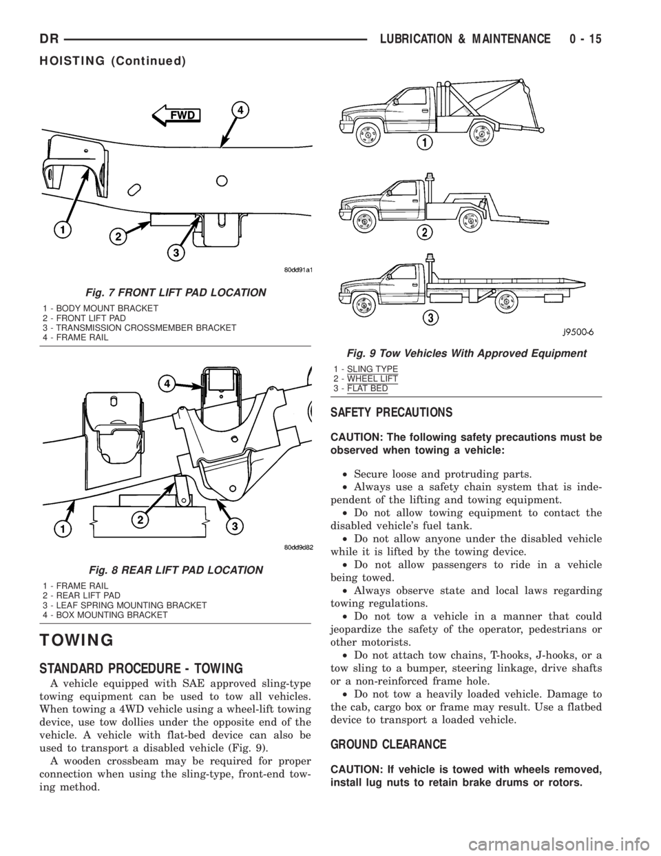
A vehicle equipped with SAE approved sling-type
towing equipment can be used to tow all vehicles.
When towing a 4WD vehicle using a wheel-lift towing
device, use tow dollies under the opposite end of the
vehicle. A vehicle with flat-bed device can also be
used to transport a disabled vehicle (Fig. 9).
A wooden crossbeam may be required for proper
connection when using the sling-type, front-end tow-
ing method.
SAFETY PRECAUTIONS
CAUTION: The following safety precautions must be
observed when towing a vehicle:
²Secure loose and protruding parts.
²Always use a safety chain system that is inde-
pendent of the lifting and towing equipment.
²Do not allow towing equipment to contact the
disabled vehicle's fuel tank.
²Do not allow anyone under the disabled vehicle
while it is lifted by the towing device.
²Do not allow passengers to ride in a vehicle
being towed.
²Always observe state and local laws regarding
towing regulations.
²Do not tow a vehicle in a manner that could
jeopardize the safety of the operator, pedestrians or
other motorists.
²Do not attach tow chains, T-hooks, J-hooks, or a
tow sling to a bumper, steering linkage, drive shafts
or a non-reinforced frame hole.
²Do not tow a heavily loaded vehicle. Damage to
the cab, cargo box or frame may result. Use a flatbed
device to transport a loaded vehicle.
GROUND CLEARANCE
CAUTION: If vehicle is towed with wheels removed,
install lug nuts to retain brake drums or rotors.
Fig. 7 FRONT LIFT PAD LOCATION
1 - BODY MOUNT BRACKET
2 - FRONT LIFT PAD
3 - TRANSMISSION CROSSMEMBER BRACKET
4 - FRAME RAIL
Fig. 8 REAR LIFT PAD LOCATION
1 - FRAME RAIL
2 - REAR LIFT PAD
3 - LEAF SPRING MOUNTING BRACKET
4 - BOX MOUNTING BRACKET
Fig. 9 Tow Vehicles With Approved Equipment
1 - SLING TYPE2 - WHEEL LIFT3 - FLAT BED
DRLUBRICATION & MAINTENANCE 0 - 15
HOISTING (Continued)
Page 31 of 2895
OPERATION
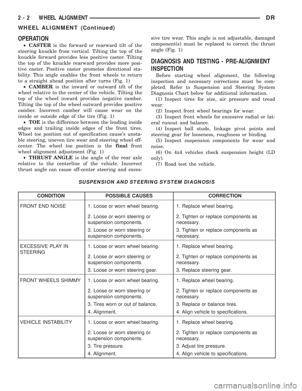
²CASTERis the forward or rearward tilt of the
steering knuckle from vertical. Tilting the top of the
knuckle forward provides less positive caster. Tilting
the top of the knuckle rearward provides more posi-
tive caster. Positive caster promotes directional sta-
bility. This angle enables the front wheels to return
to a straight ahead position after turns (Fig. 1)
²CAMBERis the inward or outward tilt of the
wheel relative to the center of the vehicle. Tilting the
top of the wheel inward provides negative camber.
Tilting the top of the wheel outward provides positive
camber. Incorrect camber will cause wear on the
inside or outside edge of the tire (Fig. 1)
²TOEis the difference between the leading inside
edges and trailing inside edges of the front tires.
Wheel toe position out of specification cause's unsta-
ble steering, uneven tire wear and steering wheel off-
center. The wheel toe position is thefinalfront
wheel alignment adjustment (Fig. 1)
²THRUST ANGLEis the angle of the rear axle
relative to the centerline of the vehicle. Incorrect
thrust angle can cause off-center steering and exces-sive tire wear. This angle is not adjustable, damaged
component(s) must be replaced to correct the thrust
angle (Fig. 1)
DIAGNOSIS AND TESTING - PRE-ALIGNMENT
INSPECTION
Before starting wheel alignment, the following
inspection and necessary corrections must be com-
pleted. Refer to Suspension and Steering System
Diagnosis Chart below for additional information.
(1) Inspect tires for size, air pressure and tread
wear.
(2) Inspect front wheel bearings for wear.
(3) Inspect front wheels for excessive radial or lat-
eral runout and balance.
(4) Inspect ball studs, linkage pivot points and
steering gear for looseness, roughness or binding.
(5) Inspect suspension components for wear and
noise.
(6) On 4x4 vehicles check suspension height (LD
only).
(7) Road test the vehicle.
SUSPENSION AND STEERING SYSTEM DIAGNOSIS
CONDITION POSSIBLE CAUSES CORRECTION
FRONT END NOISE 1. Loose or worn wheel bearing. 1. Replace wheel bearing.
2. Loose or worn steering or
suspension components.2. Tighten or replace components as
necessary.
3. Loose or worn steering or
suspension components.3. Tighten or replace components as
necessary.
EXCESSIVE PLAY IN
STEERING1. Loose or worn wheel bearing. 1. Replace wheel bearing.
2. Loose or worn steering or
suspension components.2. Tighten or replace components as
necessary.
3. Loose or worn steering gear. 3. Replace steering gear.
FRONT WHEELS SHIMMY 1. Loose or worn wheel bearing. 1. Replace wheel bearing.
2. Loose or worn steering or
suspension components.2. Tighten or replace components as
necessary.
3. Tires worn or out of balance. 3. Replace or balance tires.
4. Alignment. 4. Align vehicle to specifications.
VEHICLE INSTABILITY 1. Loose or worn wheel bearing. 1. Replace wheel bearing.
2. Loose or worn steering or
suspension components.2. Tighten or replace components as
necessary.
3. Tire pressure. 3. Adjust tire pressure.
4. Alignment. 4. Align vehicle to specifications.
2 - 2 WHEEL ALIGNMENTDR
WHEEL ALIGNMENT (Continued)
Page 32 of 2895
CONDITION POSSIBLE CAUSES CORRECTION
EXCESSIVE STEERING
EFFORT1. Loose or worn steering gear. 1. Replace steering gear.
2. Column coupler binding. 2. Replace coupler.
3. Tire pressure. 3. Adjust tire pressure.
4. Alignment. 4. Align vehicle to specifications.
VEHICLE PULLS TO ONE
SIDE1. Tire pressure. 1. Adjust tire pressure.
2. Tire. 2. Criss-Cross Front Tires.
3. Alignment. 3. Align vehicle to specifications.
4. Loose or worn steering or
suspension components.4. Tighten or replace components as
necessary.
5. Radial tire lead. 5. Rotate or replace tire as necessary.
6. Brake pull. 6. Repair brake as necessary.
7. Weak or broken spring. 7. Replace spring.
8. Ride height (LD) 4WD only. 8. Measure and adjust ride height. (LD
only)
STANDARD PROCEDURE
STANDARD PROCEDURE - HEIGHT
MEASUREMENT - 4WD (LD)
The vehicle suspension height MUST be measured
and adjusted before performing wheel alignment pro-
cedure. Also when front suspension components have
been replaced. This measure must be performed with
the vehicle supporting it's own weight and taken on
both sides of the vehicle.
(1) Inspect tires and set to correct pressure.
(2) Jounce the front of the vehicle.
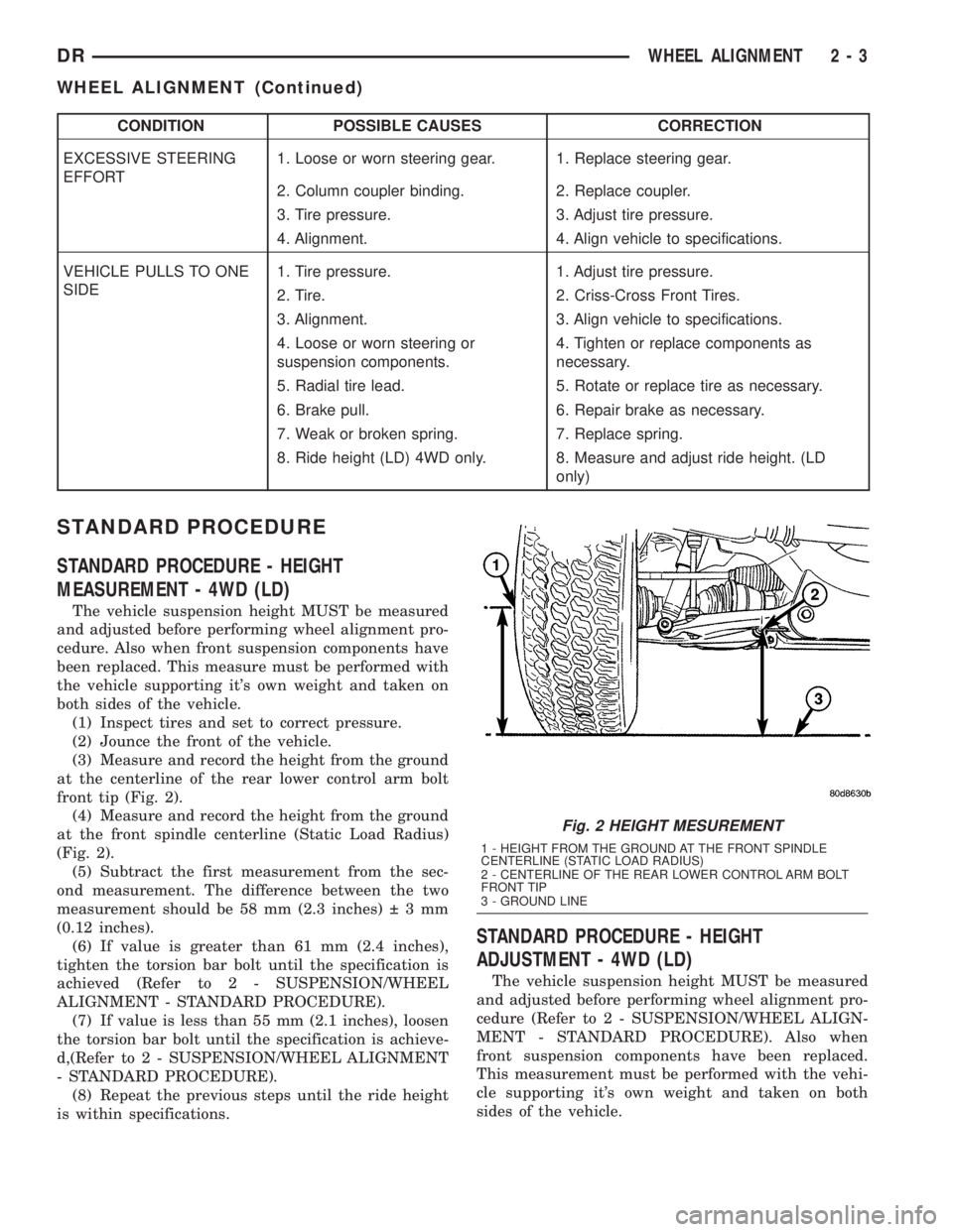
(3) Measure and record the height from the ground
at the centerline of the rear lower control arm bolt
front tip (Fig. 2).
(4) Measure and record the height from the ground
at the front spindle centerline (Static Load Radius)
(Fig. 2).
(5) Subtract the first measurement from the sec-
ond measurement. The difference between the two
measurement should be 58 mm (2.3 inches) 3mm
(0.12 inches).
(6) If value is greater than 61 mm (2.4 inches),
tighten the torsion bar bolt until the specification is
achieved (Refer to 2 - SUSPENSION/WHEEL
ALIGNMENT - STANDARD PROCEDURE).
(7) If value is less than 55 mm (2.1 inches), loosen
the torsion bar bolt until the specification is achieve-
d,(Refer to 2 - SUSPENSION/WHEEL ALIGNMENT
- STANDARD PROCEDURE).
(8) Repeat the previous steps until the ride height
is within specifications.
STANDARD PROCEDURE - HEIGHT
ADJUSTMENT - 4WD (LD)
The vehicle suspension height MUST be measured
and adjusted before performing wheel alignment pro-
cedure (Refer to 2 - SUSPENSION/WHEEL ALIGN-
MENT - STANDARD PROCEDURE). Also when
front suspension components have been replaced.
This measurement must be performed with the vehi-
cle supporting it's own weight and taken on both
sides of the vehicle.
Fig. 2 HEIGHT MESUREMENT
1 - HEIGHT FROM THE GROUND AT THE FRONT SPINDLE
CENTERLINE (STATIC LOAD RADIUS)
2 - CENTERLINE OF THE REAR LOWER CONTROL ARM BOLT
FRONT TIP
3 - GROUND LINE
DRWHEEL ALIGNMENT 2 - 3
WHEEL ALIGNMENT (Continued)
Page 37 of 2895
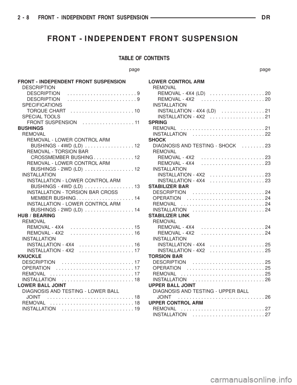
FRONT - INDEPENDENT FRONT SUSPENSION
TABLE OF CONTENTS
page page
FRONT - INDEPENDENT FRONT SUSPENSION
DESCRIPTION
DESCRIPTION........................9
DESCRIPTION........................9
SPECIFICATIONS
TORQUE CHART......................10
SPECIAL TOOLS
FRONT SUSPENSION..................11
BUSHINGS
REMOVAL
REMOVAL - LOWER CONTROL ARM
BUSHINGS - 4WD (LD).................12
REMOVAL - TORSION BAR
CROSSMEMBER BUSHING..............12
REMOVAL - LOWER CONTROL ARM
BUSHINGS - 2WD (LD).................12
INSTALLATION
INSTALLATION - LOWER CONTROL ARM
BUSHINGS - 4WD (LD).................13
INSTALLATION - TORSION BAR CROSS
MEMBER BUSHING....................14
INSTALLATION - LOWER CONTROL ARM
BUSHINGS - 2WD (LD).................14
HUB / BEARING
REMOVAL
REMOVAL - 4X4......................15
REMOVAL - 4X2......................16
INSTALLATION
INSTALLATION - 4X4...................16
INSTALLATION - 4X2...................17
KNUCKLE
DESCRIPTION.........................17
OPERATION...........................17
REMOVAL.............................17
INSTALLATION.........................18
LOWER BALL JOINT
DIAGNOSIS AND TESTING - LOWER BALL
JOINT..............................18
REMOVAL.............................18
INSTALLATION.........................19LOWER CONTROL ARM
REMOVAL
REMOVAL - 4X4 (LD)...................20
REMOVAL - 4X2......................20
INSTALLATION
INSTALLATION - 4X4 (LD)...............21
INSTALLATION - 4X2...................21
SPRING
REMOVAL.............................21
INSTALLATION.........................22
SHOCK
DIAGNOSIS AND TESTING - SHOCK........23
REMOVAL
REMOVAL - 4X2......................23
REMOVAL - 4X4......................23
INSTALLATION
INSTALLATION - 4X2...................23
INSTALLATION - 4X4...................23
STABILIZER BAR
DESCRIPTION.........................24
OPERATION...........................24
REMOVAL.............................24
INSTALLATION.........................24
STABILIZER LINK
REMOVAL
REMOVAL - 4X4......................24
REMOVAL - 4X2......................24
INSTALLATION
INSTALLATION - 4X4...................25
INSTALLATION - 4X2...................25
TORSION BAR
DESCRIPTION.........................25
OPERATION...........................25
REMOVAL.............................25
INSTALLATION.........................26
UPPER BALL JOINT
DIAGNOSIS AND TESTING - UPPER BALL
JOINT..............................26
UPPER CONTROL ARM
REMOVAL.............................27
INSTALLATION.........................27
2 - 8 FRONT - INDEPENDENT FRONT SUSPENSIONDR
Page 41 of 2895
BUSHINGS
REMOVAL
REMOVAL - LOWER CONTROL ARM
BUSHINGS - 4WD (LD)
(1) Remove the lower control arm (Refer to 2 -
SUSPENSION/FRONT/LOWER CONTROL ARM -
REMOVAL).
(2) Secure the control arm in a vise.
NOTE: Extreme pressure lubrication must be used
on the threaded portions of the tool. This will
increase the longevity of the tool and insure proper
operation during the removal and installation pro-
cess.
FRAME MOUNTED BUSHING
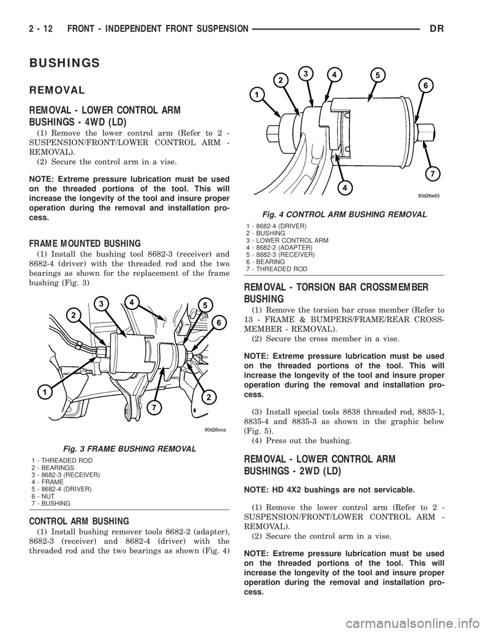
(1) Install the bushing tool 8682-3 (receiver) and
8682-4 (driver) with the threaded rod and the two
bearings as shown for the replacement of the frame
bushing (Fig. 3)
CONTROL ARM BUSHING
(1) Install bushing remover tools 8682-2 (adapter),
8682-3 (receiver) and 8682-4 (driver) with the
threaded rod and the two bearings as shown (Fig. 4)
REMOVAL - TORSION BAR CROSSMEMBER
BUSHING
(1) Remove the torsion bar cross member (Refer to
13 - FRAME & BUMPERS/FRAME/REAR CROSS-
MEMBER - REMOVAL).
(2) Secure the cross member in a vise.
NOTE: Extreme pressure lubrication must be used
on the threaded portions of the tool. This will
increase the longevity of the tool and insure proper
operation during the removal and installation pro-
cess.
(3) Install special tools 8838 threaded rod, 8835-1,
8835-4 and 8835-3 as shown in the graphic below
(Fig. 5).
(4) Press out the bushing.
REMOVAL - LOWER CONTROL ARM
BUSHINGS - 2WD (LD)
NOTE: HD 4X2 bushings are not servicable.
(1) Remove the lower control arm (Refer to 2 -
SUSPENSION/FRONT/LOWER CONTROL ARM -
REMOVAL).
(2) Secure the control arm in a vise.
NOTE: Extreme pressure lubrication must be used
on the threaded portions of the tool. This will
increase the longevity of the tool and insure proper
operation during the removal and installation pro-
cess.
Fig. 3 FRAME BUSHING REMOVAL
1 - THREADED ROD
2 - BEARINGS
3 - 8682-3 (RECEIVER)
4 - FRAME
5 - 8682-4 (DRIVER)
6 - NUT
7 - BUSHING
Fig. 4 CONTROL ARM BUSHING REMOVAL
1 - 8682-4 (DRIVER)
2 - BUSHING
3 - LOWER CONTROL ARM
4 - 8682-2 (ADAPTER)
5 - 8682-3 (RECEIVER)
6 - BEARING
7 - THREADED ROD
2 - 12 FRONT - INDEPENDENT FRONT SUSPENSIONDR