dash wiring DODGE RAM 2003 Service Repair Manual
[x] Cancel search | Manufacturer: DODGE, Model Year: 2003, Model line: RAM, Model: DODGE RAM 2003Pages: 2895, PDF Size: 83.15 MB
Page 286 of 2895
(3) Install clutch disc, pressure plate and trans-
mission.
LINKAGE
REMOVAL
CAUTION: The hydraulic linkage has a quick dis-
connect at the slave cylinder. This fitting should
never be disconnected or tampered with. Once the
hydraulic line is connected to the slave cylinder, it
should never be disconnected.
(1) Raise and support vehicle.
(2) Remove nuts attaching slave cylinder to studs
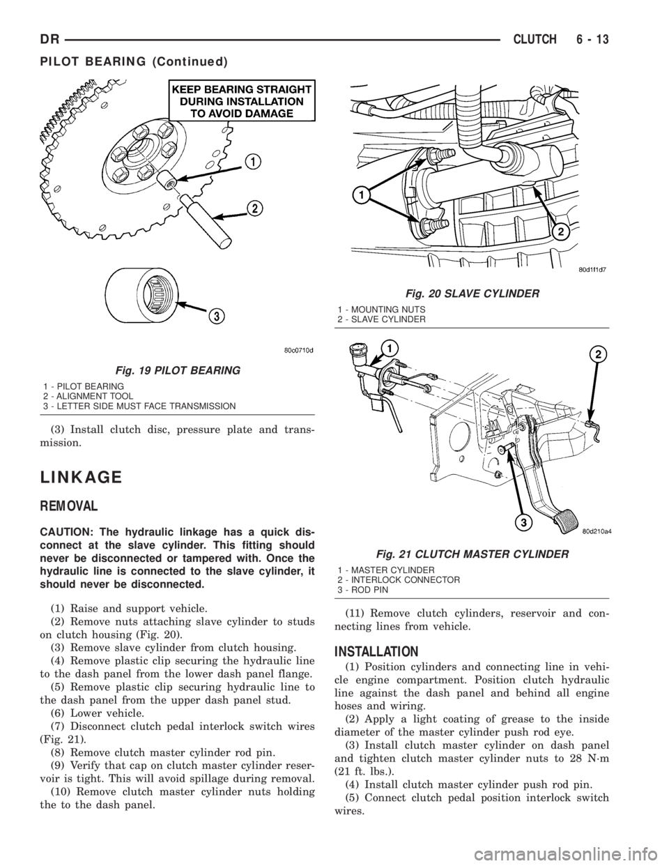
on clutch housing (Fig. 20).
(3) Remove slave cylinder from clutch housing.
(4) Remove plastic clip securing the hydraulic line
to the dash panel from the lower dash panel flange.
(5) Remove plastic clip securing hydraulic line to
the dash panel from the upper dash panel stud.
(6) Lower vehicle.
(7) Disconnect clutch pedal interlock switch wires
(Fig. 21).
(8) Remove clutch master cylinder rod pin.
(9) Verify that cap on clutch master cylinder reser-
voir is tight. This will avoid spillage during removal.
(10) Remove clutch master cylinder nuts holding
the to the dash panel.(11) Remove clutch cylinders, reservoir and con-
necting lines from vehicle.
INSTALLATION
(1) Position cylinders and connecting line in vehi-
cle engine compartment. Position clutch hydraulic
line against the dash panel and behind all engine
hoses and wiring.
(2) Apply a light coating of grease to the inside
diameter of the master cylinder push rod eye.
(3) Install clutch master cylinder on dash panel
and tighten clutch master cylinder nuts to 28 N´m
(21 ft. lbs.).
(4) Install clutch master cylinder push rod pin.
(5) Connect clutch pedal position interlock switch
wires.
Fig. 19 PILOT BEARING
1 - PILOT BEARING
2 - ALIGNMENT TOOL
3 - LETTER SIDE MUST FACE TRANSMISSION
Fig. 20 SLAVE CYLINDER
1 - MOUNTING NUTS
2 - SLAVE CYLINDER
Fig. 21 CLUTCH MASTER CYLINDER
1 - MASTER CYLINDER
2 - INTERLOCK CONNECTOR
3 - ROD PIN
DRCLUTCH 6 - 13
PILOT BEARING (Continued)
Page 474 of 2895
REMOVAL
CAUTION: Base ignition timing is not adjustable on
any engine. Distributors do not have built in centrif-
ugal or vacuum assisted advance. Base ignition
timing and timing advance are controlled by the
Powertrain Control Module (PCM). Because a con-
ventional timing light can not be used to adjust dis-
tributor position after installation, note position of
distributor before removal.
(1) Disconnect negative cable from battery.
(2) Remove air cleaner tubing.
(3) Remove distributor cap from distributor (two
screws).
(4) Mark the position of distributor housing in
relationship to engine or dash panel. This is done to
aid in installation.
(5) Before distributor is removed, the number one
cylinder must be brought to the Top Dead Center
(TDC) firing position.
(6) Attach a socket to the Crankshaft Vibration
Damper mounting bolt.
(7) Slowly rotate engine clockwise, as viewed from
front, until indicating mark on crankshaft vibration
damper is aligned to 0 degree (TDC) mark on timing
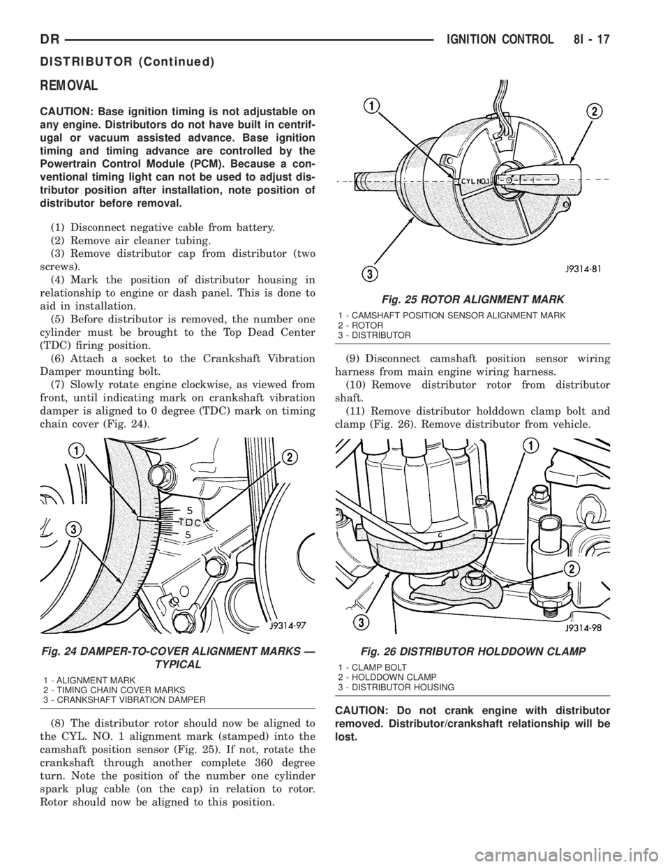
chain cover (Fig. 24).
(8) The distributor rotor should now be aligned to
the CYL. NO. 1 alignment mark (stamped) into the
camshaft position sensor (Fig. 25). If not, rotate the
crankshaft through another complete 360 degree
turn. Note the position of the number one cylinder
spark plug cable (on the cap) in relation to rotor.
Rotor should now be aligned to this position.(9) Disconnect camshaft position sensor wiring
harness from main engine wiring harness.
(10) Remove distributor rotor from distributor
shaft.
(11) Remove distributor holddown clamp bolt and
clamp (Fig. 26). Remove distributor from vehicle.
CAUTION: Do not crank engine with distributor
removed. Distributor/crankshaft relationship will be
lost.
Fig. 24 DAMPER-TO-COVER ALIGNMENT MARKS Ð
TYPICAL
1 - ALIGNMENT MARK
2 - TIMING CHAIN COVER MARKS
3 - CRANKSHAFT VIBRATION DAMPER
Fig. 25 ROTOR ALIGNMENT MARK
1 - CAMSHAFT POSITION SENSOR ALIGNMENT MARK
2 - ROTOR
3 - DISTRIBUTOR
Fig. 26 DISTRIBUTOR HOLDDOWN CLAMP
1 - CLAMP BOLT
2 - HOLDDOWN CLAMP
3 - DISTRIBUTOR HOUSING
DRIGNITION CONTROL 8I - 17
DISTRIBUTOR (Continued)
Page 704 of 2895
8W-01 WIRING DIAGRAM INFORMATION
TABLE OF CONTENTS
page page
WIRING DIAGRAM INFORMATION
DESCRIPTION
DESCRIPTION - HOW TO USE WIRING
DIAGRAMS...........................1
DESCRIPTION - CIRCUIT INFORMATION....5
DESCRIPTION - CIRCUIT FUNCTIONS......6
DESCRIPTION - SECTION IDENTIFICATION
AND INFORMATION....................6
DESCRIPTION - CONNECTOR, GROUND
AND SPLICE INFORMATION..............7
WARNING
WARNINGS - GENERAL.................7
DIAGNOSIS AND TESTING - WIRING
HARNESS............................7
STANDARD PROCEDURE
STANDARD PROCEDURE -
ELECTROSTATIC DISCHARGE (ESD)
SENSITIVE DEVICES...................8
STANDARD PROCEDURE - TESTING OF
VOLTAGE POTENTIAL...................9
STANDARD PROCEDURE - TESTING FOR
CONTINUITY..........................9STANDARD PROCEDURE - TESTING FOR A
SHORT TO GROUND...................9
STANDARD PROCEDURE - TESTING FOR A
SHORT TO GROUND ON FUSES
POWERING SEVERAL LOADS...........10
STANDARD PROCEDURE - TESTING FOR A
VOLTAGE DROP......................10
SPECIAL TOOLS
WIRING/TERMINAL....................10
CONNECTOR
REMOVAL.............................11
INSTALLATION.........................11
DIODE
REMOVAL.............................14
INSTALLATION.........................14
TERMINAL
REMOVAL.............................14
INSTALLATION.........................14
WIRE
STANDARD PROCEDURE - WIRE SPLICING . . 15
WIRING DIAGRAM
INFORMATION
DESCRIPTION
DESCRIPTION - HOW TO USE WIRING
DIAGRAMS
DaimlerChrysler Corporation wiring diagrams are
designed to provide information regarding the vehi-
cles wiring content. In order to effectively use the
wiring diagrams to diagnose and repair
DaimlerChrysler Corporation vehicles, it is important
to understand all of their features and characteris-
tics.
Diagrams are arranged such that the power (B+)
side of the circuit is placed near the top of the page,
and the ground (B-) side of the circuit is placed near
the bottom of the page (Fig. 1).
All switches, components, and modules are shown
in the at rest position with the doors closed and the
key removed from the ignition (Fig. 2).Components are shown two ways. A solid line
around a component indicates that the component is
complete. A dashed line around the component indi-
cates that the component is being shown is not com-
plete. Incomplete components have a reference
number to indicate the page where the component is
shown complete.
It is important to realize that no attempt is made
on the diagrams to represent components and wiring
as they appear on the vehicle. For example, a short
piece of wire is treated the same as a long one. In
addition, switches and other components are shown
as simply as possible, with regard to function only.
SYMBOLS
International symbols are used throughout the wir-
ing diagrams. These symbols are consistent with
those being used around the world (Fig. 3).
DR8W-01 WIRING DIAGRAM INFORMATION 8W - 01 - 1
Page 1802 of 2895
INSTALLATION
WARNING: BEFORE SERVICING THE STEERING
COLUMN THE AIRBAG SYSTEM MUST BE DIS-
ARMED. REFER TO ELECTRICAL RESTRAINT SYS-
TEM FOR SERVICE PROCEDURES. FAILURE TO DO
SO MAY RESULT IN ACCIDENTAL DEPLOYMENT OF
THE AIRBAG AND POSSIBLE PERSONAL INJURY.
CAUTION: All fasteners must be torqued to specifi-
cation to ensure proper operation of the steering
column.
(1) Position the steering column on the dash panel
support and loosely install the mounting nuts.
(2) Firmly slide the steering column upward
against the studs in dash panel and hand tighten the
nuts.
(3) Install the steering shaft coupler on the steer-
ing shaft and loosely install anewbolt.
(4) Center steering column in dash opening and
tighten mounting nuts to 28 N´m (250 in. lbs.).
NOTE: Torque the upper left nut first then the lower
right nut. Then torque the lower left nut then the
upper right nut.
NOTE: A new bolt must be used for reinstallation.
(5) Tighten the coupler bolt to 57 N´m (42 ft. lbs.).
(6) Install a new brake light switch (Refer to 8 -
ELECTRICAL/LAMPS/LIGHTING - EXTERIOR/
BRAKE LAMP SWITCH - REMOVAL).(7) Install the shifter cable. (Refer to 21 - TRANS-
MISSION/TRANSAXLE/AUTOMATIC - 32RH/GEAR
SHIFT CABLE - INSTALLATION)
(8) Connect the wiring harness to the column.
(9) Install the SKIM module.
(10) Install the clockspring(Refer to 8 - ELECTRI-
CAL/RESTRAINTS/CLOCKSPRING - REMOVAL).
(11) Install the shrouds.
(12) Install the steering column opening cover
(Refer to 23 - BODY/INSTRUMENT PANEL/STEER-
ING COLUMN OPENING COVER - INSTALLA-
TION).
(13) Align the spline on the wheel hub to shaft.
(14) Then install the steering wheel and install a
newbolt. Tighten the bolt to 61 N´m (45 ft. lbs.).
(15) Install the airbag (Refer to 8 - ELECTRICAL/
RESTRAINTS/DRIVER AIRBAG - INSTALLATION).
(16) Install the two steering wheel switches.
(17) Install the tilt lever handle.
(18) Install the negative battery terminal.
(19) Test the operation of the horn, Electronic
PRNDL Indicator, lights and any other functions that
are steering column operated.IGNITION SWITCH
DESCRIPTION
The ignition switch is located on the steering col-
umn. It is used as the main on/off switching device
for most electrical components. The mechanical key
cylinder is used to engage/disengage the electrical
ignition switch.
OPERATION
Vehicles equipped with an automatic trans-
mission and a steering column mounted shifter:
an interlock device is located within the shift cable.
This interlock device is used to lock the transmission
shifter in the PARK position when the key cylinder is
in any position and the brake pedal is not depressed.
DIAGNOSIS AND TESTING - IGNITION SWITCH
TEST AND REPAIR
If the key removal effort is excessive on a vehicle
with a automatic transmission first adjust the shift
linkage, (Refer to 21 - TRANSMISSION/TRANS-
AXLE/AUTOMATIC - 46RE/GEAR SHIFT CABLE -
ADJUSTMENTS).
If the ignition switch effort is excessive remove the
ignition key cylinder from the steering column. (Refer
to 19 - STEERING/COLUMN/LOCK CYLINDER
HOUSING - REMOVAL). Check the turning effort of
the key cylinder. If the ignition key cylinder effort is
excessive replace the key cylinder.
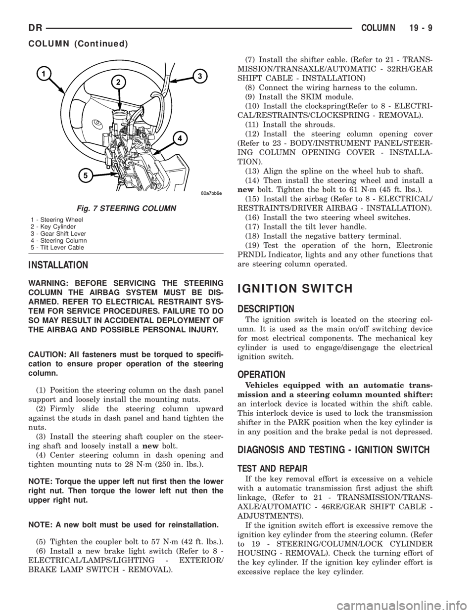
Fig. 7 STEERING COLUMN
1 - Steering Wheel
2 - Key Cylinder
3 - Gear Shift Lever
4 - Steering Column
5 - Tilt Lever Cable
DRCOLUMN 19 - 9
COLUMN (Continued)
Page 2049 of 2895
(4) Lower the vehicle.
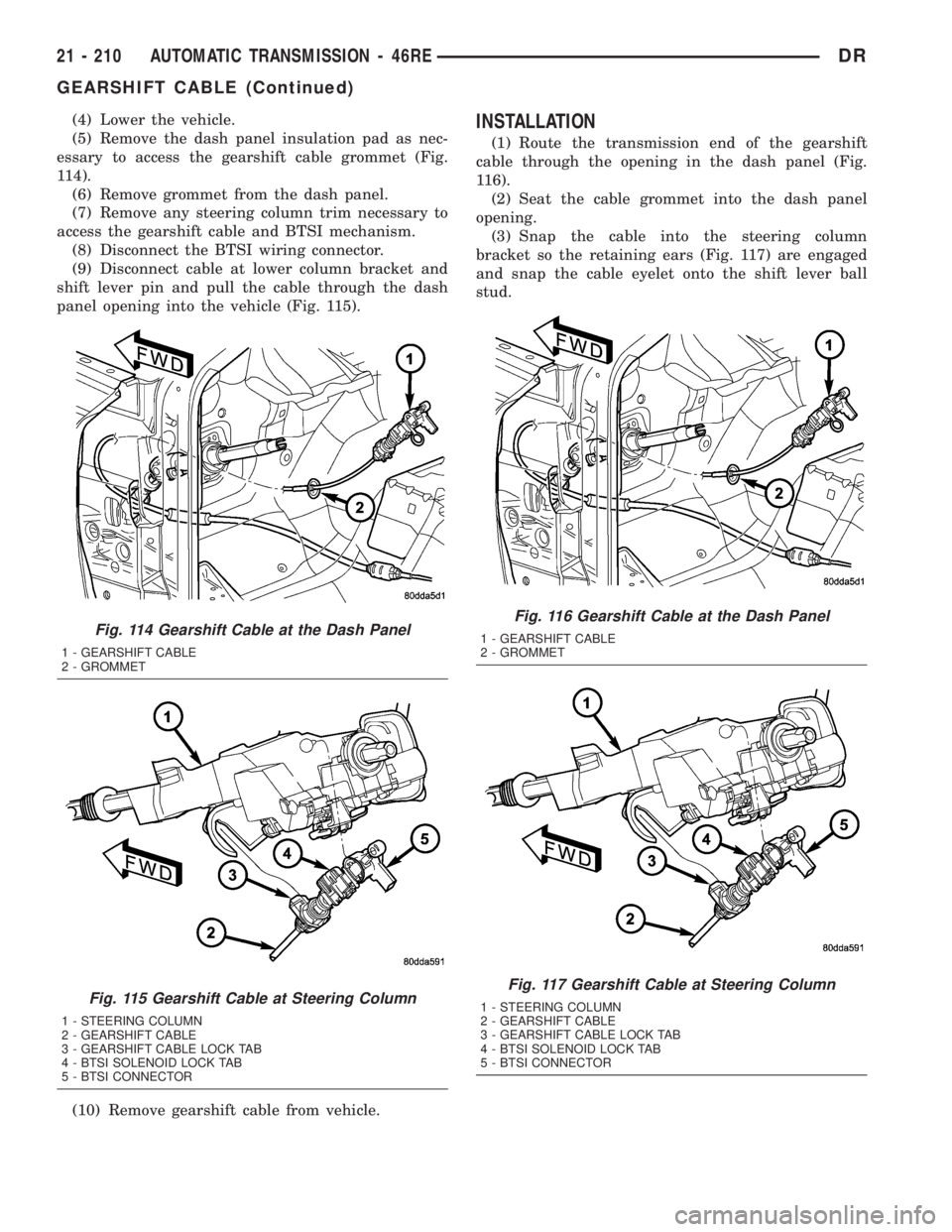
(5) Remove the dash panel insulation pad as nec-
essary to access the gearshift cable grommet (Fig.
114).
(6) Remove grommet from the dash panel.
(7) Remove any steering column trim necessary to
access the gearshift cable and BTSI mechanism.
(8) Disconnect the BTSI wiring connector.
(9) Disconnect cable at lower column bracket and
shift lever pin and pull the cable through the dash
panel opening into the vehicle (Fig. 115).
(10) Remove gearshift cable from vehicle.INSTALLATION
(1) Route the transmission end of the gearshift
cable through the opening in the dash panel (Fig.
116).
(2) Seat the cable grommet into the dash panel
opening.
(3) Snap the cable into the steering column
bracket so the retaining ears (Fig. 117) are engaged
and snap the cable eyelet onto the shift lever ball
stud.
Fig. 114 Gearshift Cable at the Dash Panel
1 - GEARSHIFT CABLE
2 - GROMMET
Fig. 115 Gearshift Cable at Steering Column
1 - STEERING COLUMN
2 - GEARSHIFT CABLE
3 - GEARSHIFT CABLE LOCK TAB
4 - BTSI SOLENOID LOCK TAB
5 - BTSI CONNECTOR
Fig. 116 Gearshift Cable at the Dash Panel
1 - GEARSHIFT CABLE
2 - GROMMET
Fig. 117 Gearshift Cable at Steering Column
1 - STEERING COLUMN
2 - GEARSHIFT CABLE
3 - GEARSHIFT CABLE LOCK TAB
4 - BTSI SOLENOID LOCK TAB
5 - BTSI CONNECTOR
21 - 210 AUTOMATIC TRANSMISSION - 46REDR
GEARSHIFT CABLE (Continued)
Page 2229 of 2895
(4) Lower the vehicle.
(5) Remove the dash panel insulation pad as nec-
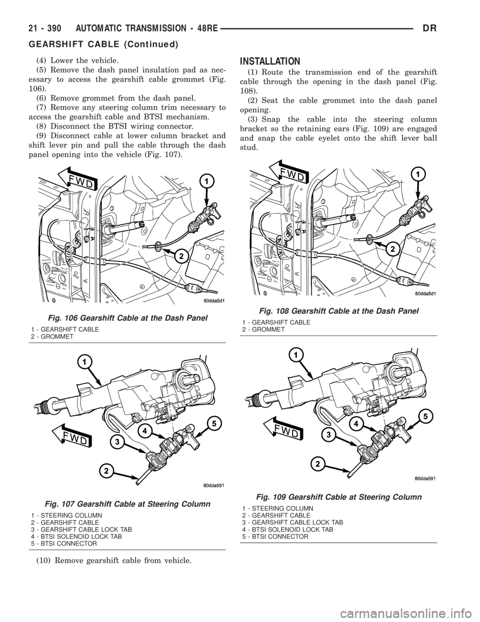
essary to access the gearshift cable grommet (Fig.
106).
(6) Remove grommet from the dash panel.
(7) Remove any steering column trim necessary to
access the gearshift cable and BTSI mechanism.
(8) Disconnect the BTSI wiring connector.
(9) Disconnect cable at lower column bracket and
shift lever pin and pull the cable through the dash
panel opening into the vehicle (Fig. 107).
(10) Remove gearshift cable from vehicle.INSTALLATION
(1) Route the transmission end of the gearshift
cable through the opening in the dash panel (Fig.
108).
(2) Seat the cable grommet into the dash panel
opening.
(3) Snap the cable into the steering column
bracket so the retaining ears (Fig. 109) are engaged
and snap the cable eyelet onto the shift lever ball
stud.
Fig. 106 Gearshift Cable at the Dash Panel
1 - GEARSHIFT CABLE
2 - GROMMET
Fig. 107 Gearshift Cable at Steering Column
1 - STEERING COLUMN
2 - GEARSHIFT CABLE
3 - GEARSHIFT CABLE LOCK TAB
4 - BTSI SOLENOID LOCK TAB
5 - BTSI CONNECTOR
Fig. 108 Gearshift Cable at the Dash Panel
1 - GEARSHIFT CABLE
2 - GROMMET
Fig. 109 Gearshift Cable at Steering Column
1 - STEERING COLUMN
2 - GEARSHIFT CABLE
3 - GEARSHIFT CABLE LOCK TAB
4 - BTSI SOLENOID LOCK TAB
5 - BTSI CONNECTOR
21 - 390 AUTOMATIC TRANSMISSION - 48REDR
GEARSHIFT CABLE (Continued)
Page 2384 of 2895
(4) Lower the vehicle.
(5) Remove the dash panel insulation pad as nec-
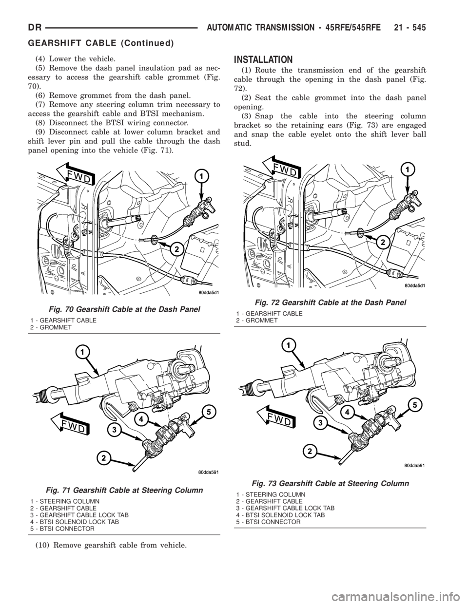
essary to access the gearshift cable grommet (Fig.
70).
(6) Remove grommet from the dash panel.
(7) Remove any steering column trim necessary to
access the gearshift cable and BTSI mechanism.
(8) Disconnect the BTSI wiring connector.
(9) Disconnect cable at lower column bracket and
shift lever pin and pull the cable through the dash
panel opening into the vehicle (Fig. 71).
(10) Remove gearshift cable from vehicle.INSTALLATION
(1) Route the transmission end of the gearshift
cable through the opening in the dash panel (Fig.
72).
(2) Seat the cable grommet into the dash panel
opening.
(3) Snap the cable into the steering column
bracket so the retaining ears (Fig. 73) are engaged
and snap the cable eyelet onto the shift lever ball
stud.
Fig. 70 Gearshift Cable at the Dash Panel
1 - GEARSHIFT CABLE
2 - GROMMET
Fig. 71 Gearshift Cable at Steering Column
1 - STEERING COLUMN
2 - GEARSHIFT CABLE
3 - GEARSHIFT CABLE LOCK TAB
4 - BTSI SOLENOID LOCK TAB
5 - BTSI CONNECTOR
Fig. 72 Gearshift Cable at the Dash Panel
1 - GEARSHIFT CABLE
2 - GROMMET
Fig. 73 Gearshift Cable at Steering Column
1 - STEERING COLUMN
2 - GEARSHIFT CABLE
3 - GEARSHIFT CABLE LOCK TAB
4 - BTSI SOLENOID LOCK TAB
5 - BTSI CONNECTOR
DRAUTOMATIC TRANSMISSION - 45RFE/545RFE 21 - 545
GEARSHIFT CABLE (Continued)
Page 2697 of 2895
WELD LOCATIONS
SPECIFICATIONS
INDEX
DESCRIPTION FIGURE
FENDER BRACE, CLOSURE TUBE AND FRAME MOUNTING BRACKET TO FRONT
FENDER SUPPORT, FRONT FENDER AND RADIATOR TUBE31
STEERING COLUMN SUPPORT, CONNECTOR WIRING BRACKET AND WELD NUTS
TO LOWER PLENUM PANEL32
WIPER ATTACHING WELD NUTS AND VACUUM RESERVOIR ATTACHING STUDS TO
COWL PAR PANEL33
DASH PANEL TO FRONT FLOOR PAN 34
DASH PANEL TO LOWER PLENUM PANEL 35
LOWER PLENUM PANEL TO COWL BACK PANEL 36
FRONT FENDER AND RADIATOR TUBE DASH PANEL, INSTRUMENT PANEL
MOUNTING BRACKET, AND WELD NUTS TO COWL SIDE PANEL - LEFT SIDE37
DASH PANEL, LOWER PLENUM PANEL AND COWL PANEL BAR TO COWL SIDE
PANEL - LEFT SIDE38
FRONT FENDER AND RADIATOR TUBE DASH PANEL, INSTRUMENT PANEL
MOUNTING BRACKET AND WELD NUTS TO COWL SIDE PANEL - RIGHT SIDE39
DASH PANEL, LOWER PLENUM PANEL AND COWL PANEL BAR TO COWL SIDE
PANEL - RIGHT SIDE40
REINFORCEMENT AND HEADLAMP MOUNTING PANEL TO OUTER FENDER PANEL 41
SEAT MOUNTING FRONT BRACKETS TO SEAT MOUNTING FRONT CROSSMEMBER
TO FRONT FLOOR PAN42
AIR BAG MODULE BRACKET SHIFTER MOUNTING PLATE AND REAR FLOOR PANE
TO FRONT FLOOR PAN43
RIGHT TO LEFT REAR FLOOR CROSSMEMBER AND RIGHT TO LEFT SEAT
MOUNTING CROSSMEMBER44
REAR FLOOR CROSSMEMBER, SEAT MOUNTING CROSSMEMBER AND
UNDERBODY SUPPORT TO FLOOR SILL45
SEAT MOUNTING FRONT CROSSMEMBER TO FRONT FLOOR PAN TO UNDERBODY
SUPPORT46
FRONT SEAT MOUNTING CROSSMEMBERS TO FRONT SEAT MOUNTING BRACKET
TO FRONT FLOOR PAN47
REAR FLOOR CROSSMEMBERS TO REAR FLOOR PAN 48
FLOOR SILL TO FRONT SEAT MOUNTING CROSSMEMBER, FRONT AND REAR
FLOOR PAN49
AIR BAG MODULE BRACKET, SHIFTER MOUNTING PLATE AND FRONT SEAT
MOUNTING CROSSMEMBER TO FRONT FLOOR PAN50
REAR SEAT MIDDLE MOUNTING PLATE TO REAR FLOOR PAN TO FRONT FLOOR
PA N51
REAR FLOOR CROSSMEMBER, SEAT MOUNTING CROSSMEMBER AND
UNDERBODY SUPPORT TO FLOOR SILL52
LEFT REAR CROSSMEMBER TO RIGHT REAR CROSSMEMBER TO REAR FLOOR
PA N53
23 - 122 BODY STRUCTUREDR
Page 2801 of 2895
DIAGNOSIS AND TESTING - BLOWER MOTOR
WARNING: ON VEHICLES EQUIPPED WITH AIR-
BAGS, DISABLE THE AIRBAG SYSTEM BEFORE
ATTEMPTING ANY STEERING WHEEL, STEERING
COLUMN, OR INSTRUMENT PANEL COMPONENT
DIAGNOSIS OR SERVICE. DISCONNECT AND ISO-
LATE THE BATTERY NEGATIVE (GROUND) CABLE,
THEN WAIT TWO MINUTES FOR THE AIRBAG SYS-
TEM CAPACITOR TO DISCHARGE BEFORE PER-
FORMING FURTHER DIAGNOSIS OR SERVICE. THIS
IS THE ONLY SURE WAY TO DISABLE THE AIRBAG
SYSTEM. FAILURE TO TAKE THE PROPER PRE-
CAUTIONS COULD RESULT IN AN ACCIDENTAL
AIRBAG DEPLOYMENT AND POSSIBLE PERSONAL
INJURY.
For circuit descriptions and diagrams, (Refer to
Appropriate Wiring Information). Possible causes of
an inoperative blower motor include:
²Faulty fuse
²Faulty blower motor circuit wiring or wire har-
ness connectors
²Faulty blower motor resistor
²Faulty blower motor relay
²Faulty blower motor switch
²Faulty A/C Heater mode control switch
²Faulty blower motor.
Possible causes of the blower motor not operating
in all speeds include:
²Faulty blower motor switch
²Faulty blower motor resistor
²Faulty blower motor circuit wiring or wire har-
ness connectors.
VIBRATION
Possible causes of blower motor vibration include:
²Improper blower motor mounting
²Improper blower wheel mounting
²Blower wheel out of balance or bent
²Blower motor faulty.
NOISE
To verify that the blower is the source of the noise,
unplug the blower motor wire harness connector and
operate the HVAC system. If the noise goes away,
possible causes include:
²Foreign material in the HVAC housing
²Improper blower motor mounting
²Improper blower wheel mounting
²Blower motor faulty.
REMOVAL
WARNING: ON VEHICLES EQUIPPED WITH AIR-
BAGS, DISABLE THE AIRBAG SYSTEM BEFORE
ATTEMPTING ANY STEERING WHEEL, STEERINGCOLUMN, OR INSTRUMENT PANEL COMPONENT
DIAGNOSIS OR SERVICE. DISCONNECT AND ISO-
LATE THE BATTERY NEGATIVE (GROUND) CABLE,
THEN WAIT TWO MINUTES FOR THE AIRBAG SYS-
TEM CAPACITOR TO DISCHARGE BEFORE PER-
FORMING FURTHER DIAGNOSIS OR SERVICE. THIS
IS THE ONLY SURE WAY TO DISABLE THE AIRBAG
SYSTEM. FAILURE TO TAKE THE PROPER PRE-
CAUTIONS COULD RESULT IN AN ACCIDENTAL
AIRBAG DEPLOYMENT AND POSSIBLE PERSONAL
INJURY.
The blower motor is located on the passenger side
of the vehicle under the dash
(1) Disconnect and isolate the battery negative
cable.
(2) Unplug the blower motor wire harness connec-
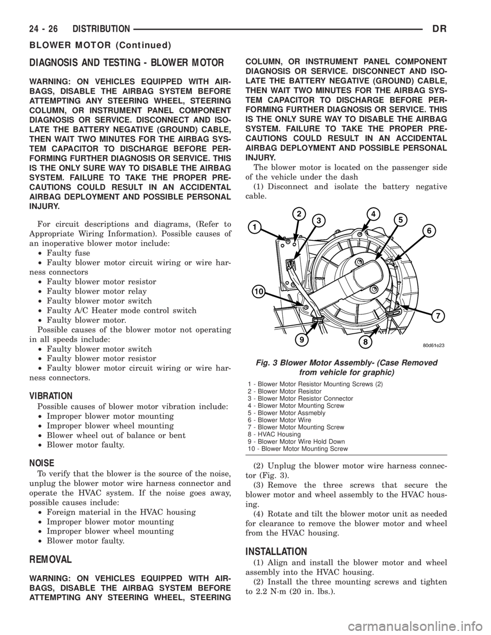
tor (Fig. 3).
(3) Remove the three screws that secure the
blower motor and wheel assembly to the HVAC hous-
ing.
(4) Rotate and tilt the blower motor unit as needed
for clearance to remove the blower motor and wheel
from the HVAC housing.
INSTALLATION
(1) Align and install the blower motor and wheel
assembly into the HVAC housing.
(2) Install the three mounting screws and tighten
to 2.2 N´m (20 in. lbs.).
Fig. 3 Blower Motor Assembly- (Case Removed
from vehicle for graphic)
1 - Blower Motor Resistor Mounting Screws (2)
2 - Blower Motor Resistor
3 - Blower Motor Resistor Connector
4 - Blower Motor Mounting Screw
5 - Blower Motor Assmebly
6 - Blower Motor Wire
7 - Blower Motor Mounting Screw
8 - HVAC Housing
9 - Blower Motor Wire Hold Down
10 - Blower Motor Mounting Screw
24 - 26 DISTRIBUTIONDR
BLOWER MOTOR (Continued)
Page 2804 of 2895
(2) Install the screws and snap clips that secure
the upper and lower HVAC housing halves to each
other. Tighten the screws to 2.2 N´m (20 in. lbs.).
(3) Install the blower motor and wheel unit in the
HVAC housing. (Refer to 24 - HEATING & AIR CON-
DITIONING/DISTRIBUTION/BLOWER MOTOR -
INSTALLATION)
(4) Install the foam seals on the flanges around
the heater core and evaporator coil tube mounting
flange of the HVAC housing. Repair or replace any
seals as required.
(5) Install the electrical wiring harness for the
acutators. Make sure the wires are routed through
all wiring retainers, replace any retainers that are
damaged or missing.
(6) Connect the wiring harness to each actuator,
making sure each connector is securely attached.
INSTALLATION
WARNING: IF THE VEHICLE IS EQUIPPED WITH AIR
CONDITIONING, REVIEW THE WARNINGS AND
CAUTIONS IN PLUMBING BEFORE PERFORMING
THE FOLLOWING OPERATION. (Refer to 24 - HEAT-
ING & AIR CONDITIONING/PLUMBING - WARNING)
(Refer to 24 - HEATING & AIR CONDITIONING/
PLUMBING - CAUTION) (Refer to 24 - HEATING &
AIR CONDITIONING/PLUMBING - CAUTION -
REFRIGERANT HOSES/LINES/TUBES PRECAU-
TIONS)
(1) Position the HVAC housing to the dash panel.
Be certain that the evaporator condensate drain tube
and the housing mounting studs are inserted into
their correct mounting holes.
(2) Install and tighten the nuts onto the HVAC
housing mounting studs. Tighten the nuts to 6.2 N´m
(55 in.lbs.).
(3) Connect the HVAC system electrical connec-
tors.
(4) Unplug or remove the tape from the heater
core tubes. Connect the heater hoses to the heater
core tubes and fill the engine cooling system(Refer to
7 - COOLING/ENGINE - STANDARD PROCE-
DURE).
(5) Unplug or remove the tape from the liquid line
and the evaporator inlet tube fittings. Connect the
liquid line coupler to the evaporator inlet tube. (Refer
to 24 - HEATING & AIR CONDITIONING/PLUMB-
ING - STANDARD PROCEDURE - A/C LINE COU-
PLERS)(6) Evacuate the refrigerant system. (Refer to 24 -
HEATING & AIR CONDITIONING/PLUMBING -
STANDARD PROCEDURE - REFRIGERANT SYS-
TEM EVACUATE)
(7) Charge the refrigerant system. (Refer to 24 -
HEATING & AIR CONDITIONING/PLUMBING -
STANDARD PROCEDURE - REFRIGERANT SYS-
TEM CHARGE)
(8) Install the instrument panel in the vehicle(Re-
fer to 23 - BODY/INSTRUMENT PANEL - INSTAL-
LATION).
(9) Connect the battery negative cable.
(10) Start the engine and check for proper opera-
tion of the heating and air conditioning systems.
(11) Run the calibration procedure.
INSTRUMENT PANEL DUCTS
REMOVAL
(1) Disconnect and isolate the battery negative
cable.
(2) Remove the HVAC assembly from the vehi-
cle(Refer to 24 - HEATING & AIR CONDITIONING/
DISTRIBUTION/HVAC HOUSING - REMOVAL).
(3) Disasemble the HVAC housing(Refer to 24 -
HEATING & AIR CONDITIONING/DISTRIBUTION/
HVAC HOUSING - DISASSEMBLY).
(4) Remove the panel door actuator from the hous-
ing if not already removed.
(5) With the actuator removed you can take the
door and shift it so that one pivot point will clear the
housing. You can then tilt the door and remove it
from the housing.
INSTALLATION
(1) Take the door and tilt it so one pivot point is
installed. The carfully install the second pivot point.
Check to be sure no binding of the door is occuring,
repair as required.
(2) Reassemble the HVAC housing(Refer to 24 -
HEATING & AIR CONDITIONING/DISTRIBUTION/
HVAC HOUSING - ASSEMBLY).
(3) Install the HVAC assembly into the vehicle(Re-
fer to 24 - HEATING & AIR CONDITIONING/DIS-
TRIBUTION/INSTRUMENT PANEL DUCTS -
INSTALLATION).
(4) Connect the battery negative cable.
DRDISTRIBUTION 24 - 29
HVAC HOUSING (Continued)