brake DODGE RAM SRT-10 2006 Service Owners Manual
[x] Cancel search | Manufacturer: DODGE, Model Year: 2006, Model line: RAM SRT-10, Model: DODGE RAM SRT-10 2006Pages: 5267, PDF Size: 68.7 MB
Page 1947 of 5267
VALVES & SEATS - INTAKE/EXHAUST
DESCRIPTION
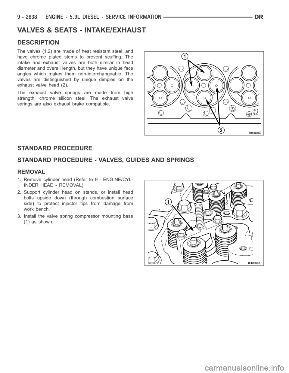
The valves (1,2) are made of heat resistant steel, and
have chrome plated stems to prevent scuffing. The
intake and exhaust valves are both similar in head
diameter and overall length, but they have unique face
angles which makes them non-interchangeable. The
valves are distinguished by unique dimples on the
exhaust valve head (2).
The exhaust valve springs are made from high
strength, chrome silicon steel. The exhaust valve
springs are also exhaust brake compatible.
STANDARD PROCEDURE
STANDARD PROCEDURE - VALVES, GUIDES AND SPRINGS
REMOVAL
1. Remove cylinder head (Refer to 9 - ENGINE/CYL-
INDER HEAD - REMOVAL).
2. Support cylinder head on stands, or install head
bolts upside down (through combustion surface
side) to protect injector tips from damage from
work bench.
3. Install the valve spring compressor mounting base
(1) as shown.
Page 2035 of 5267
31. Disconnect A/C lines and electrical connector from
A/C compressor. Plug holes in A/C compressor to
prevent debris from entering A/C compressor.
32. Disconnect brake booster vacuum hose and fuel
line to fuel rail.
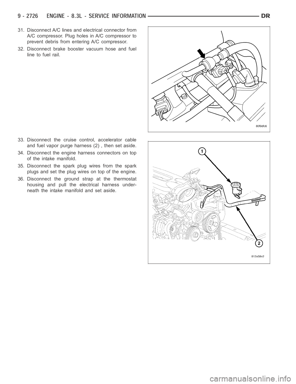
33. Disconnect the cruise control, accelerator cable
and fuel vapor purge harness (2) , then set aside.
34. Disconnect the engine harness connectors on top
of the intake manifold.
35. Disconnect the spark plug wires from the spark
plugs and set the plug wires on top of the engine.
36. Disconnect the ground strap at the thermostat
housing and pull the electrical harness under-
neath the intake manifold and set aside.
Page 2038 of 5267
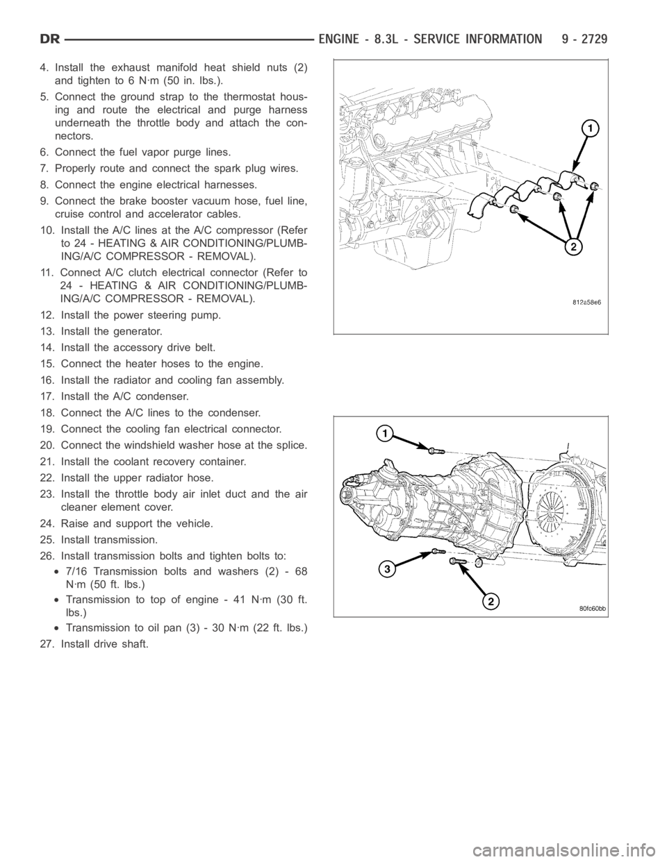
4. Install the exhaust manifold heat shield nuts (2)
and tighten to 6 Nꞏm (50 in. lbs.).
5. Connect the ground strap to the thermostat hous-
ing and route the electrical and purge harness
underneath the throttle body and attach the con-
nectors.
6. Connect the fuel vapor purge lines.
7. Properly route and connect the spark plug wires.
8. Connect the engine electrical harnesses.
9. Connect the brake booster vacuum hose, fuel line,
cruise control and accelerator cables.
10. Install the A/C lines at the A/C compressor (Refer
to 24 - HEATING & AIR CONDITIONING/PLUMB-
ING/A/C COMPRESSOR - REMOVAL).
11. Connect A/C clutch electrical connector (Refer to
24 - HEATING & AIR CONDITIONING/PLUMB-
ING/A/C COMPRESSOR - REMOVAL).
12. Install the power steering pump.
13. Install the generator.
14. Install the accessory drive belt.
15. Connect the heater hoses to the engine.
16. Install the radiator and cooling fan assembly.
17. Install the A/C condenser.
18. Connect the A/C lines to the condenser.
19. Connect the cooling fan electrical connector.
20. Connect the windshield washer hose at the splice.
21. Install the coolant recovery container.
22. Install the upper radiator hose.
23. Install the throttle body air inlet duct and the air
cleaner element cover.
24. Raise and support the vehicle.
25. Install transmission.
26. Install transmission bolts and tighten bolts to:
7/16 Transmission bolts and washers (2) - 68
Nꞏm (50 ft. lbs.)
Transmission to top of engine - 41 Nꞏm (30 ft.
lbs.)
Transmission to oil pan (3) - 30 Nꞏm (22 ft. lbs.)
27. Install drive shaft.
Page 2040 of 5267
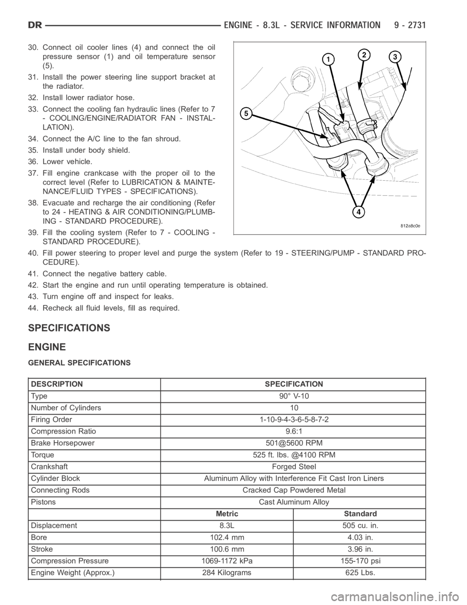
30. Connect oil cooler lines (4) and connect the oil
pressure sensor (1) and oil temperature sensor
(5).
31. Install the power steering line support bracket at
the radiator.
32. Install lower radiator hose.
33. Connect the cooling fan hydraulic lines (Refer to 7
- COOLING/ENGINE/RADIATOR FAN - INSTAL-
LATION).
34. Connect the A/C line to the fan shroud.
35. Install under body shield.
36. Lower vehicle.
37. Fill engine crankcase with the proper oil to the
correct level (Refer to LUBRICATION & MAINTE-
NANCE/FLUID TYPES - SPECIFICATIONS).
38. Evacuate and recharge the air conditioning (Refer
to 24 - HEATING & AIR CONDITIONING/PLUMB-
ING - STANDARD PROCEDURE).
39. Fill the cooling system (Refer to 7 - COOLING -
STANDARD PROCEDURE).
40. Fill power steering to proper leveland purge the system (Refer to 19 - STEERING/PUMP - STANDARD PRO-
CEDURE).
41. Connect the negative battery cable.
42. Start the engine and run until operating temperature is obtained.
43. Turn engine off and inspect for leaks.
44. Recheck all fluid levels, fill as required.
SPECIFICATIONS
ENGINE
GENERAL SPECIFICATIONS
DESCRIPTION SPECIFICATION
Ty pe 9 0° V-1 0
Number of Cylinders 10
Firing Order 1-10-9-4-3-6-5-8-7-2
Compression Ratio 9.6:1
Brake Horsepower 501@5600 RPM
Torque 525 ft. lbs. @4100 RPM
Crankshaft Forged Steel
Cylinder Block Aluminum Alloy with Interference Fit Cast Iron Liners
Connecting Rods Cracked Cap Powdered Metal
Pistons Cast Aluminum Alloy
Metric Standard
Displacement 8.3L 505 cu. in.
Bore 102.4 mm 4.03 in.
Stroke 100.6 mm 3.96 in.
Compression Pressure 1069-1172 kPa 155-170 psi
Engine Weight (Approx.) 284 Kilograms 625 Lbs.
Page 2058 of 5267
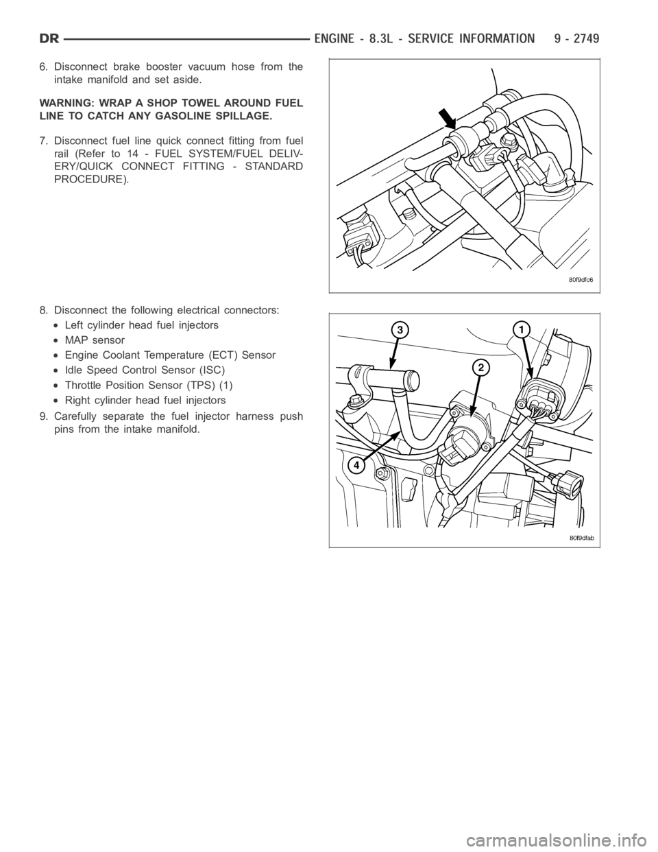
6. Disconnect brake booster vacuum hose from the
intake manifold and set aside.
WARNING: WRAP A SHOP TOWEL AROUND FUEL
LINE TO CATCH ANY GASOLINE SPILLAGE.
7. Disconnect fuel line quick connect fitting from fuel
rail (Refer to 14 - FUEL SYSTEM/FUEL DELIV-
ERY/QUICK CONNECT FITTING - STANDARD
PROCEDURE).
8. Disconnect the following electrical connectors:
Left cylinder head fuel injectors
MAP sensor
Engine Coolant Temperature (ECT) Sensor
Idle Speed Control Sensor (ISC)
Throttle Position Sensor (TPS) (1)
Right cylinder head fuel injectors
9. Carefully separate the fuel injector harness push
pins from the intake manifold.
Page 2060 of 5267

INSTALLATION
CAUTION: When cleaning the intake manifold and
cylinder head mating surfaces, do not use a metal
scraper because the surfaces could be cut or
ground. Instead, use a wooden or plastic scraper.
NOTE: Care must be taken to protect the intake
manifold powder coat from possible scrapes and
abrasions.
1. Clean gasket surfaces and remove covering from
intake manifold openings.
2. Carefully install the intake manifold gaskets (2) and
alignment pins (1).
3. Set the intake manifold in position on the engine.
Install intake manifold bolts and tighten initially to 1
Nꞏm (10 in. lbs.). Tighten bolts starting at the center
and working outward to 11 Nꞏm (95 in. lbs.).
4. Connect CCV hoses to left and right cylinder head
covers.
5. Connect fuel line to fuel rail. Pull backward on the
quick connect fitting to ensure complete insertion.
6. Connect the brake booster vacuum hose.
Page 2069 of 5267

COVER(S)-CYLINDER HEAD
REMOVAL
LEFT CYLINDER HEAD COVER
NOTE: Care must be taken to protect the cylinder
head cover powder coating from scrapes and
abrasions.
1. Disconnect CCV hose from cylinder head cover.
2. Disconnect left side spark plug wires by pulling on
the boot straight out in line with plug. Dislodge
spark plug wire retainers from cylinder head cover
studs. Reposition spark plug wires aside.
3. Disconnect the power brake booster vacuum hose
at the intake manifold and set aside.
NOTE: For reassembly purposes, identify location
of cylinder head cover attaching studs and bolts.
4. Remove cylinder head cover fasteners. Remove
cylinder head cover (2) from engine.
RIGHT CYLINDER HEAD COVER
NOTE: Care must be taken to protect the cylinder
head cover powder coating from scrapes and
abrasions.
1. Disconnect CCV hose from cylinder head cover.
2. Disconnect right side spark plug wires by pulling on
the boot straight out in line with plug. Dislodge
spark plug wire retainers from cylinder head cover
studs. Reposition spark plug wires aside.
3. Remove the oil level indicator tube fastener and
position tube aside.
NOTE: For reassembly purposes, identify location
of cylinder head cover attaching studs and bolts.
4. Remove cylinder head cover fasteners.
5. Remove cylinder head cover (1) from engine.
Page 2070 of 5267

INSTALLATION
LEFT CYLINDER HEAD COVER
NOTE: Care must be taken to protect the cylinder
head covers powder coating from scrapes and
abrasions.
1. Inspect cylinder head cover gasket. Replace as
necessary.
2. Place cylinder head cover onto cylinder head.
Install and tighten cylinder head cover fasteners to
11 Nꞏm (95 in. lbs.) in sequence shown in.
3. Connect spark plug wires. Position spark plug wire
retainers onto cylinder head cover studs.
4. Connect CCV hose to cylinder head cover.
5. Connect the power brake booster vacuum hose to the intake manifold port.
RIGHT CYLINDER HEAD COVER
1. Inspect cylinder head cover gasket. Replace as
necessary.
2. Place cylinder head cover onto cylinder head.
Install and tighten cylinder head cover fasteners to
11 Nꞏm (95 in. lbs.) in sequence shown in.
3. Position the oil level indicator tube into position.
Tighten fastener to 11 Nꞏm (95 in. lbs.).
4. Connect spark plug wires. Position spark plug wire
retainers onto cylinder head cover studs.
5. Connect CCV hose to cylinder head cover.
Page 2080 of 5267
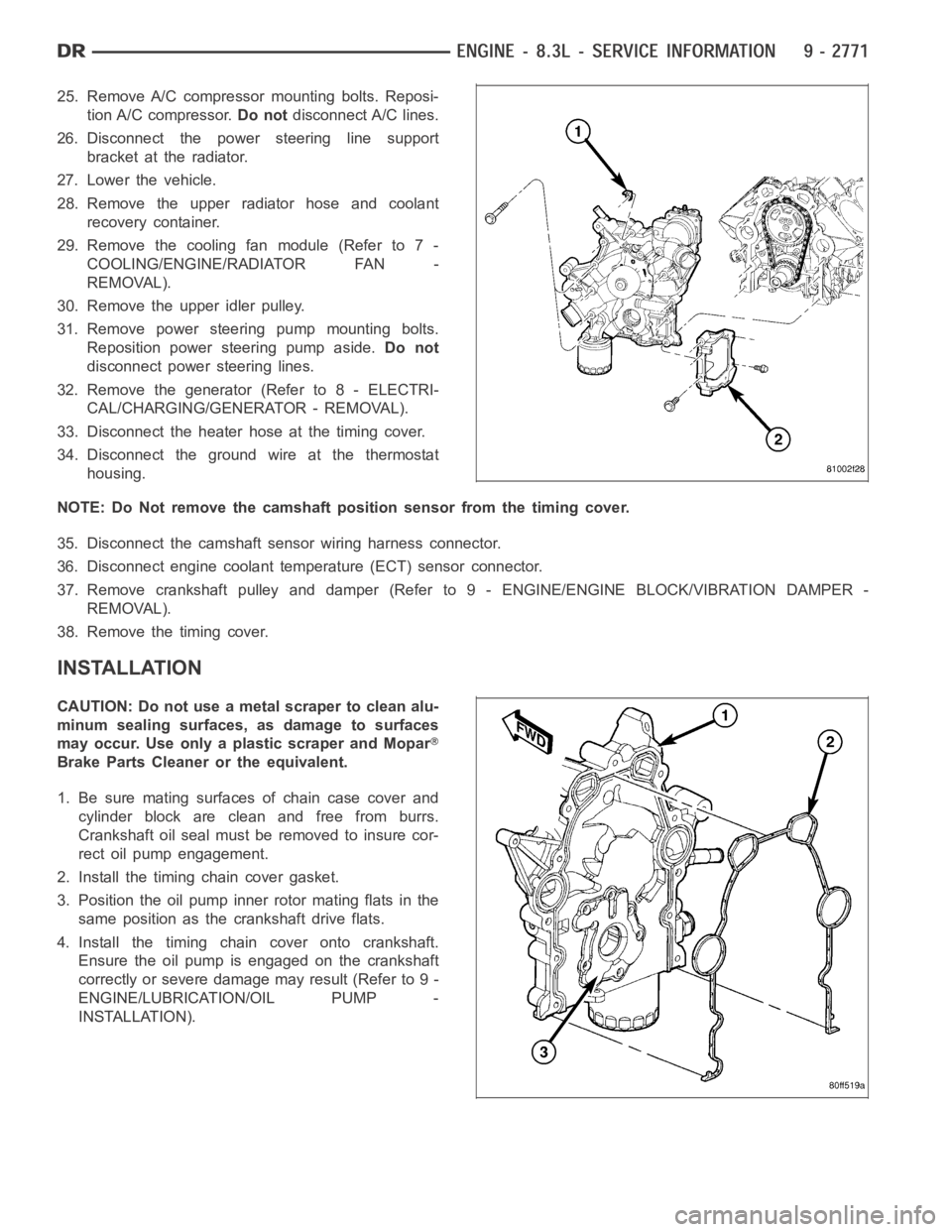
25. Remove A/C compressor mounting bolts. Reposi-
tion A/C compressor.Do notdisconnect A/C lines.
26. Disconnect the power steering line support
bracket at the radiator.
27. Lower the vehicle.
28. Remove the upper radiator hose and coolant
recovery container.
29. Remove the cooling fan module (Refer to 7 -
COOLING/ENGINE/RADIATOR FAN -
REMOVAL).
30. Remove the upper idler pulley.
31. Remove power steering pump mounting bolts.
Reposition power steering pump aside.Do not
disconnect power steering lines.
32. Remove the generator (Refer to 8 - ELECTRI-
CAL/CHARGING/GENERATOR - REMOVAL).
33. Disconnect the heater hose at the timing cover.
34. Disconnect the ground wire at the thermostat
housing.
NOTE: Do Not remove the camshaft position sensor from the timing cover.
35. Disconnect the camshaft sensor wiring harness connector.
36. Disconnect engine coolant temperature (ECT) sensor connector.
37. Remove crankshaft pulley and damper (Refer to 9 - ENGINE/ENGINE BLOCK/VIBRATION DAMPER -
REMOVAL).
38. Remove the timing cover.
INSTALLATION
CAUTION: Do not use a metal scraper to clean alu-
minum sealing surfaces, as damage to surfaces
may occur. Use only a plastic scraper and Mopar
Brake Parts Cleaner or the equivalent.
1. Be sure mating surfaces of chain case cover and
cylinder block are clean and free from burrs.
Crankshaft oil seal must be removed to insure cor-
rect oil pump engagement.
2. Install the timing chain cover gasket.
3. Position the oil pump inner rotor mating flats in the
same position as the crankshaft drive flats.
4. Install the timing chain cover onto crankshaft.
Ensure the oil pump is engaged on the crankshaft
correctly or severe damage may result (Refer to 9 -
ENGINE/LUBRICATION/OIL PUMP -
INSTALLATION).
Page 2104 of 5267
BLOCK-ENGINE
DESCRIPTION
The cylinder block is made of a sand-cast aluminum alloy. The cylinder block has interference-fit cast iron cylinder
liners. The cylinder liners are thermally installed during block manufacturing; they are not serviceable items.
Six iron main bearing caps use four bolts per cap; two vertical and two horizontal. A crankshaft oil scraper is
attached to the main bearing caps via extended main bearing cap bolts and nuts.
STANDARD PROCEDURE - CYLINDER BORE HONING
Before honing, stuff plenty of clean shop towels under
the bores and over the crankshaft to keep abrasive
materials from entering the crankshaft area.
1. Used carefully, the Cylinder Bore Sizing Hone
C-823, equipped with 220 grit stones, is the best
tool for this job. In addition to deglazing, it will
reduce taper and out-of-round, as well as removing
light scuffing, scoring and scratches. Usually, a few
strokes will clean up a bore and maintain the
required limits.
CAUTION: DO NOT use rigid type hones to remove
cylinder wall glaze.
2. Deglazing of the cylinder walls may be done if the
cylinder bore is straight and round. Use a cylinder
surfacing hone, Honing Tool C-3501, equipped with
280 grit stones (C-3501-3810). about 20-60
strokes, depending on the bore condition, will be
sufficient to provide a satisfactory surface. Using
honing oil C-3501-3880, or a light honing oil, avail-
able from major oil distributors.
CAUTION: DO NOT use engine or transmission oil, mineral spirits, or kerosene.
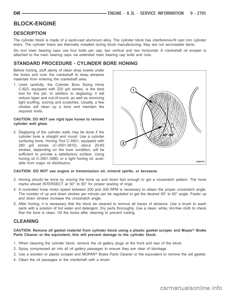
3. Honing should be done by moving the hone up and down fast enough to get a crosshatch pattern. The hone
marks should INTERSECT at 50° to 60° for proper seating of rings.
4. A controlled hone motor speed between 200 and 300 RPM is necessary to obtain the proper crosshatch angle.
The number of up and down strokes per minute can be regulated to get the desired 50° to 60° angle. Faster up
and down strokes increase the crosshatch angle.
5. After honing, it is necessary that the block be cleaned to remove all traces of abrasive. Use a brush to wash
parts with a solution of hot water and detergent. Dry parts thoroughly. Usea clean, white, lint-free cloth to check
that the bore is clean. Oil the bores after cleaning to prevent rusting.
CLEANING
CAUTION: Remove all gasket material from cylinder block using a plastic gasket scraper and MoparBrake
Parts Cleaner or the equivalent, this will prevent damage to the cylinder block.
1. When cleaning the cylinder block, remove the oil gallery plugs at the front and rear of the block.
2. Spray compressed air into all oil gallery passages to ensure they are clear of blockage.
3. Use a wooden or plastic scraper and MOPAR
Brake Parts Cleaner or the equivalent to remove the old gasket.
4. Clean the oil passages in the crankshaft with a brush.