brake DODGE RAM SRT-10 2006 Service Manual PDF
[x] Cancel search | Manufacturer: DODGE, Model Year: 2006, Model line: RAM SRT-10, Model: DODGE RAM SRT-10 2006Pages: 5267, PDF Size: 68.7 MB
Page 1392 of 5267
When Monitored:
With the engine idling and in drive, if automatic. There must not be a MAP sensor trouble code or a throttle
position sensor trouble code.
Set Condition:
Engine idle is not within 200 rpm above or 100 rpm below target idle for 14 seconds. Three separate failures
are required to set a bad trip. Two bad trips are required to set the code.
Possible Causes
GOOD TRIP EQUAL TO ZERO
VACUUM LEAK
AIR INDUCTION SYSTEM
THROTTLE BODY AND THROTTLE LINKAGE
IAC DRIVER CIRCUIT OPEN
PCM
Always perform the Pre-Diagnostic Troubleshooting procedure before proceeding. (Refer to 9 - ENGINE -
DIAGNOSIS AND TESTING)
1.GOOD TRIP EQUAL TO ZERO
Ignition on, engine not running.
NOTE: All MAP Sensor, IAC, and/or TPS codes present must be diagnosed firstbefore proceeding.
With the scan tool, read DTCs and record the related Freeze Frame data.
Is the Good Trip Counter displayed and equal to zero?
Ye s>>
Go To 2
No>>
Refer to the INTERMITTENT CONDITIONSymptom (Diagnostic Procedure).
Perform POWERTRAIN VERIFICATION TEST. (Refer to 9 - ENGINE - STANDARD PROCEDURE)
2.VACUUM LEAK
Inspect the Intake Manifold for vacuum leaks.
Inspect the Power Brake Booster for any vacuum leaks.
Inspect the PCV system for proper operation or any vacuum leaks.
Were any problems found?
Ye s>>
Repair vacuum leak as necessary.
Perform POWERTRAIN VERIFICATION TEST. (Refer to 9 - ENGINE - STANDARD PROCEDURE)
No>>
Go To 3
3.AIR INDUCTION SYSTEM
Inspect the Air Induction System for the following problems.
Restrictions: Dirty Air Cleaner, Foreign material in the air intake tube,etc.
Leaks: Air Intake tube connection, Air Cleaner housing, etc.
Were any problems found?
Ye s>>
Repair or replace as necessary.
Perform POWERTRAIN VERIFICATION TEST. (Refer to 9 - ENGINE - STANDARD PROCEDURE)
No>>
Go To 4
Page 1462 of 5267

*BRAKE SWITCH SENSE STATUS DOES NOT CHANGE ON THE SCAN TOOL
For a complete wiring diagramRefer to Section 8W.
Page 1463 of 5267
Possible Causes
(A103) FUSED B+ CIRCUIT
(Z429) BRAKE LAMP SWITCH GROUND CIRCUIT OPEN
BRAKE LAMP SWITCH
(B29) BRAKE SWITCH NO.1 SIGNAL CIRCUIT OPEN
(B29) BRAKE SWITCH NO.1 SIGNAL CIRCUIT SHORT TO GROUND
PCM
Always perform the Pre-Diagnostic Troubleshooting procedure before proceeding. (Refer to 9 - ENGINE -
DIAGNOSIS AND TESTING)
Diagnostic Test
1.SCAN TOOL DOES NOT SHOW BRAKE SW PRESSED OR RELEASED
Ignition on, engine not running.
With the scan tool in Inputs/Outputs, read the Brake Switch state.
While observing the scan tool display, press and release the brake pedal several times.
Does the scan tool display Brake Switch PRESSED and RELEASED?
Ye s>>
The Brake Lamp Switch is operating properly at this time.
Perform the POWERTRAIN VERIFICATION TEST. (Refer to 9 - ENGINE - STANDARD PROCEDURE)
No>>
Go To 2
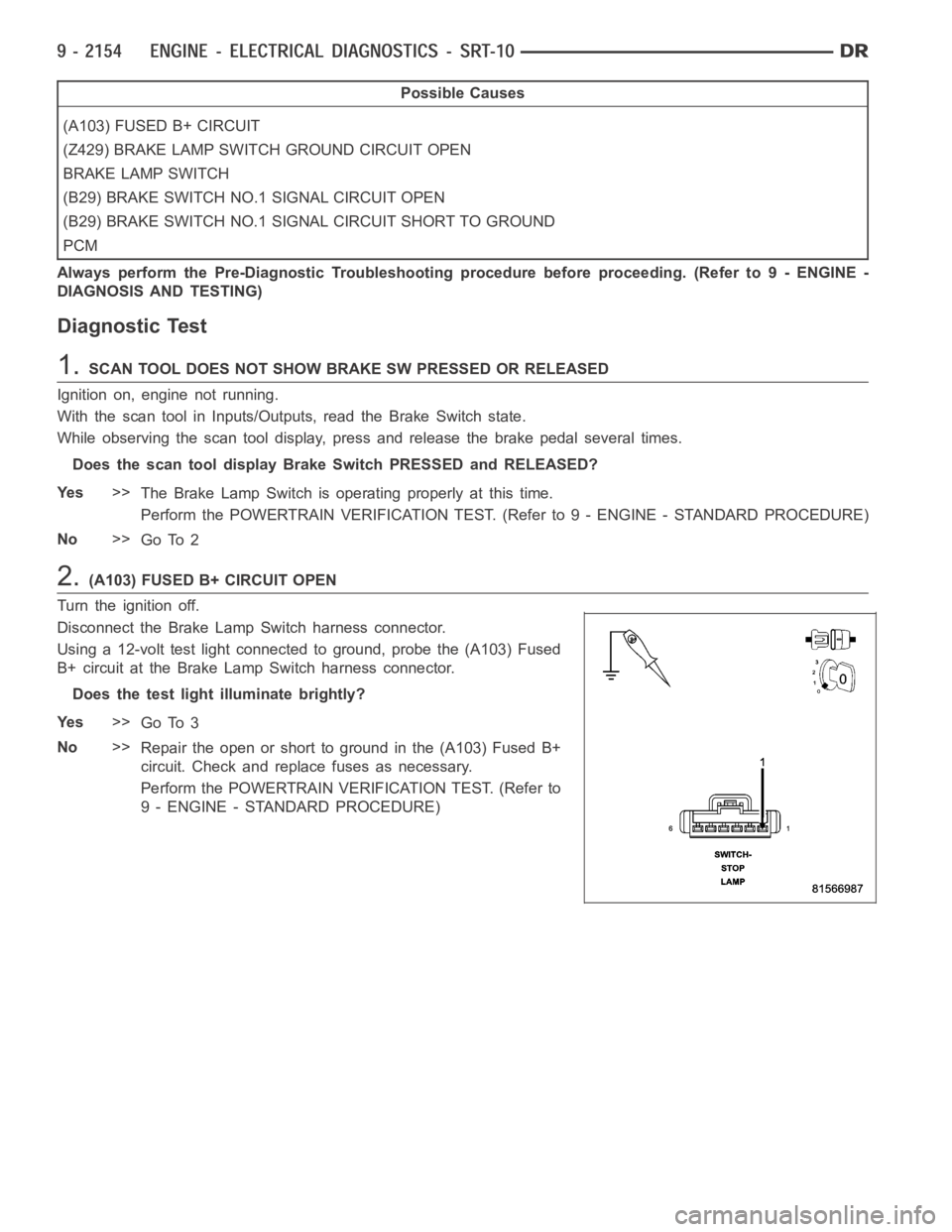
2.(A103) FUSED B+ CIRCUIT OPEN
Turn the ignition off.
Disconnect the Brake Lamp Switch harness connector.
Using a 12-volt test light connected to ground, probe the (A103) Fused
B+ circuit at the Brake Lamp Switch harness connector.
Does the test light illuminate brightly?
Ye s>>
Go To 3
No>>
Repair the open or short to ground in the (A103) Fused B+
circuit. Check and replace fuses as necessary.
Perform the POWERTRAIN VERIFICATION TEST. (Refer to
9 - ENGINE - STANDARD PROCEDURE)
Page 1464 of 5267
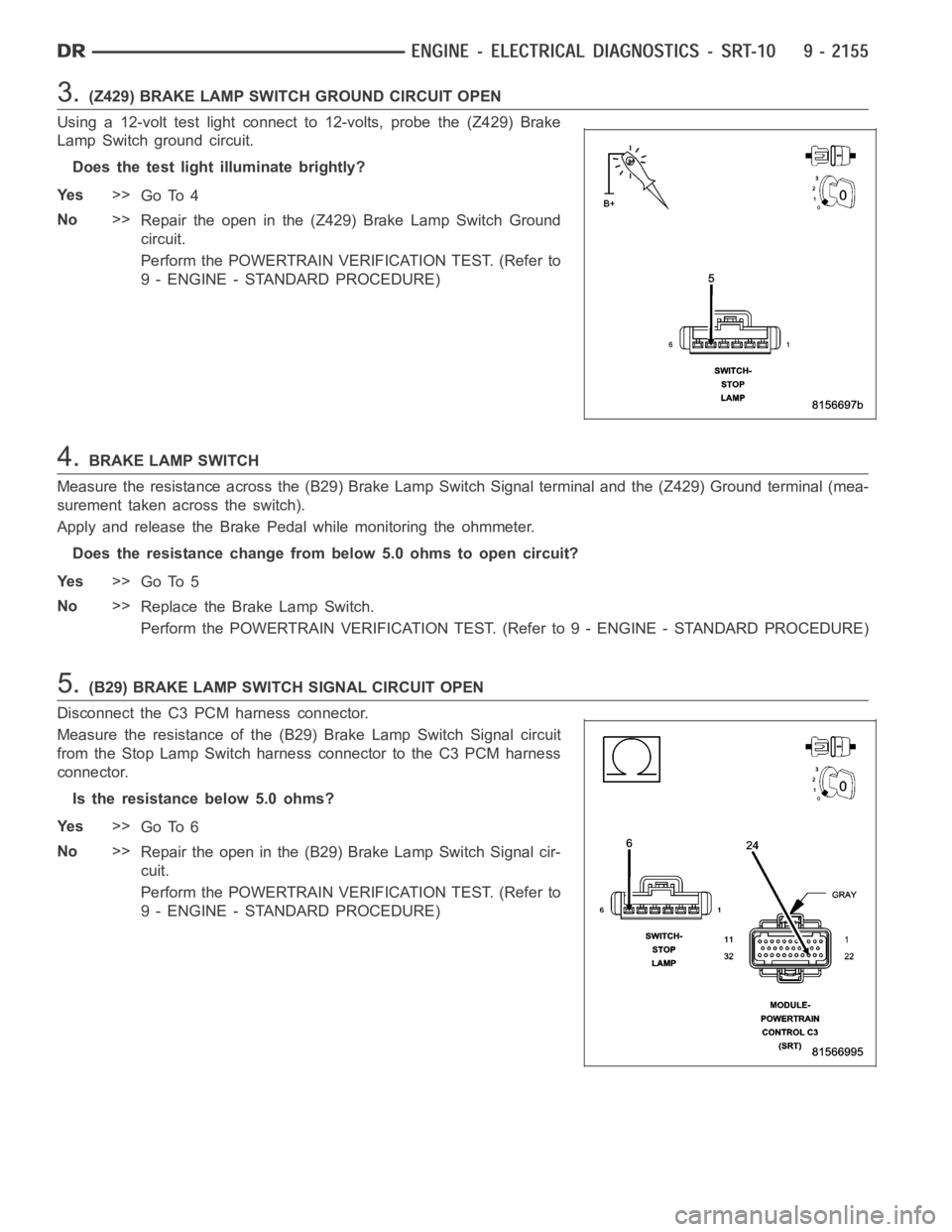
3.(Z429) BRAKE LAMP SWITCH GROUND CIRCUIT OPEN
Using a 12-volt test light connect to 12-volts, probe the (Z429) Brake
Lamp Switch ground circuit.
Does the test light illuminate brightly?
Ye s>>
Go To 4
No>>
Repair the open in the (Z429) Brake Lamp Switch Ground
circuit.
Perform the POWERTRAIN VERIFICATION TEST. (Refer to
9 - ENGINE - STANDARD PROCEDURE)
4.BRAKE LAMP SWITCH
Measure the resistance across the (B29) Brake Lamp Switch Signal terminaland the (Z429) Ground terminal (mea-
surement taken across the switch).
Apply and release the Brake Pedal while monitoring the ohmmeter.
Does the resistance change frombelow 5.0 ohms to open circuit?
Ye s>>
Go To 5
No>>
Replace the Brake Lamp Switch.
Perform the POWERTRAIN VERIFICATION TEST. (Refer to 9 - ENGINE - STANDARD PROCEDURE)
5.(B29) BRAKE LAMP SWITCH SIGNAL CIRCUIT OPEN
Disconnect the C3 PCM harness connector.
Measure the resistance of the (B29) Brake Lamp Switch Signal circuit
from the Stop Lamp Switch harness connector to the C3 PCM harness
connector.
Is the resistance below 5.0 ohms?
Ye s>>
Go To 6
No>>
Repair the open in the (B29) Brake Lamp Switch Signal cir-
cuit.
Perform the POWERTRAIN VERIFICATION TEST. (Refer to
9 - ENGINE - STANDARD PROCEDURE)
Page 1465 of 5267
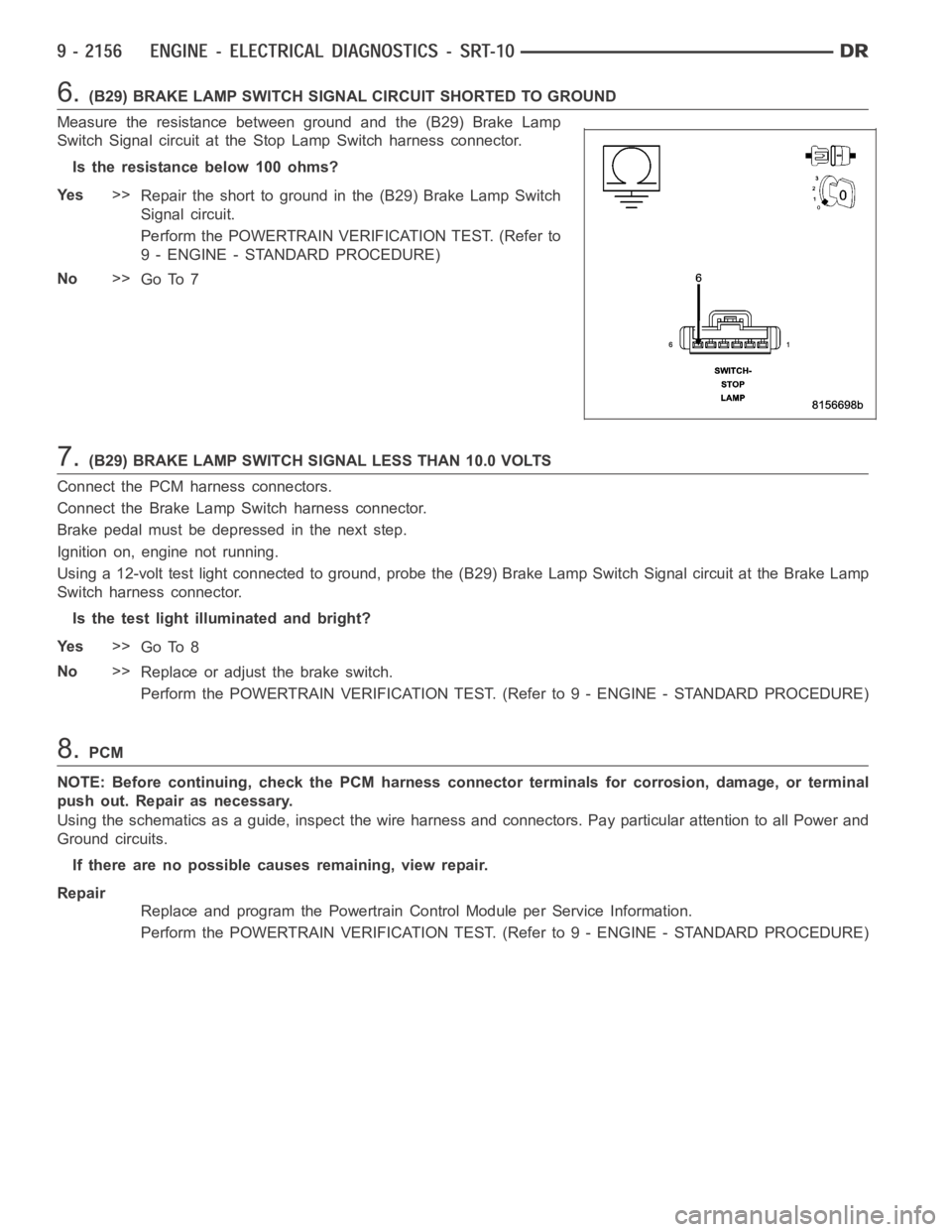
6.(B29) BRAKE LAMP SWITCH SIGNAL CIRCUIT SHORTED TO GROUND
Measure the resistance between ground and the (B29) Brake Lamp
Switch Signal circuit at the Stop Lamp Switch harness connector.
Istheresistancebelow100ohms?
Ye s>>
Repair the short to ground in the (B29) Brake Lamp Switch
Signal circuit.
Perform the POWERTRAIN VERIFICATION TEST. (Refer to
9 - ENGINE - STANDARD PROCEDURE)
No>>
Go To 7
7.(B29) BRAKE LAMP SWITCH SIGNAL LESS THAN 10.0 VOLTS
Connect the PCM harness connectors.
Connect the Brake Lamp Switch harness connector.
Brake pedal must be depressed in the next step.
Ignition on, engine not running.
Using a 12-volt test light connected to ground, probe the (B29) Brake Lamp Switch Signal circuit at the Brake Lamp
Switch harness connector.
Is the test light illuminated and bright?
Ye s>>
Go To 8
No>>
Replace or adjust the brake switch.
Perform the POWERTRAIN VERIFICATION TEST. (Refer to 9 - ENGINE - STANDARD PROCEDURE)
8.PCM
NOTE: Before continuing, check the PCM harness connector terminals for corrosion, damage, or terminal
push out. Repair as necessary.
Using the schematics as a guide, inspect the wire harness and connectors. Pay particular attention to all Power and
Ground circuits.
If there are no possible causes remaining, view repair.
Repair
Replace and program the Powertrain Control Module per Service Information.
Perform the POWERTRAIN VERIFICATION TEST. (Refer to 9 - ENGINE - STANDARD PROCEDURE)
Page 1481 of 5267
B2277–CAN GATEWAY INTERNAL (GATEWAY)
For a complete wiring diagramRefer to Section 8W.
When Monitored:
With the ignition on.
Set Condition:
If the Gateway Module detects an internal failure.
Possible Causes
GATEWAY MODULE
Diagnostic Test
1.REPLACE THE GATEWAY MODULE
Repair
Replace the Gateway Module in accordance with the Service Information.
Perform GATEWAY VERIFICATION TEST - VER 1. (Refer to 9 - ENGINE - STANDARD PROCEDURE).
U0001–CAN C BUS CIRCUIT (GATEWAY)
For a complete wiring diagramRefer to Section 8W.
When Monitored:
With the ignition on.
Set Condition:
If the Gateway Module detects a short in either CAN C Bus circuit.
Refer to U0001-CAN C BUS CIRCUIT(in 8 - ELECTRICAL/ELECTRONIC CONTROL MODULES - DIAGNOSIS
AND TESTING)for the diagnostic test procedure.
U0002–CAN C BUS PERFORMANCE (GATEWAY)
For a complete wiring diagramRefer to Section 8W.
When Monitored:
With the ignition on.
Set Condition:
If the Gateway Module detects a short in either CAN C Bus circuit.
Refer to U0001-CAN C BUS CIRCUIT(in 8 - ELECTRICAL/ELECTRONIC CONTROL MODULES - DIAGNOSIS
AND TESTING)for the diagnostic test procedure.
U0100–LOST COMMUNICATION WITH ECM/PCM (GATEWAY)
For a complete wiring diagramRefer to Section 8W.
When Monitored:
With the ignition on.
Set Condition:
If the Gateway Module looses communication with the Powertrain Control Module (PCM).
Refer to U0100-LOST COMMUNICATION WITH ECM/PCM(in 8 - ELECTRICAL/ELECTRONIC CONTROL MOD-
ULES - DIAGNOSIS AND TESTING)for the diagnostic test procedure.
U0121–LOST COMMUNICATION WITH ANTI-LOCK BRAKE MODULE (GATEWAY)
For a complete wiring diagramRefer to Section 8W.
Page 1482 of 5267
When Monitored:
With the ignition on.
Set Condition:
If the Gateway Module looses communication with the Anti-Lock Brake Module.
Refer to U0121-LOST COMMUNICATION WITH ANTI-LOCK BRAKE MODULE(in 8 - ELECTRICAL/ELECTRONIC
CONTROL MODULES - DIAGNOSIS AND TESTING)for the diagnostic test procedure.
U0155–LOST COMMUNICATION WITH CLUSTER/CCN (GATEWAY)
For a complete wiring diagramRefer to Section 8W.
When Monitored:
With the ignition on.
Set Condition:
If the Gateway Module looses communication with the Cluster (CCN).
Refer to U0155-LOST COMMUNICATION WITH CLUSTER/CCN(in 8 - ELECTRICAL/ELECTRONIC CONTROL
MODULES - DIAGNOSIS AND TESTING)for the diagnostic test procedure.
U0168–LOST COMMUNICATION WITHVEHICLE SECURITY CONTROL MODULE -
SKREEM/WCM (GATEWAY)
For a complete wiring diagramRefer to Section 8W.
When Monitored:
With the ignition on.
Set Condition:
If the Gateway Module looses communication with the Vehicle Security Control Module (SKREEM/WCM).
Refer to U0168-LOST COMMUNICATION WITH VEHICLE SECURITY CONTROL MODULE (SKREEM/WCM)(in 8
- ELECTRICAL/ELECTRONIC CONTROL MODULES - DIAGNOSIS AND TESTING)for the diagnostic test proce-
dure.
STANDARD PROCEDURE
Page 1483 of 5267
POWERTRAIN VERIFICATION TEST
For a complete wiring diagramRefer to Section 8W.
Diagnostic Test
1.SELECTING THE PROPER VERIFICATION TEST
The following verification test are for different repairs. Select the appropriate Verification test for the
repair that has been completed.
Speed Control repair
Go To 2
Charging System repair
Go To 3
NVLD System repair
Go To 4
All other repairs
Go To 5
2.POWERTRAIN VERIFICATION TEST 1
NOTE: 1. If this vehicle is equipped with an Electronic Throttle Control system, and the APP Sensors, PCM,
or Throttle Body Assembly have been replaced, use the scan tool to perform the ETC RELEARN function.
NOTE: 2. After completing the Powertrain Verification Test the Transmission Verification Test must be per-
formed.
NOTE: 3. If the PCM has been replaced and the correct VIN and mileage have notbeen programmed, a DTC
will set in the ABS Module, Airbag Module and the SKIM/SKREEM.
NOTE: 4. If the vehicle is equipped with a Sentry Key Remote Entry, Secret Key data must be updated. Refer
to the Service Information for the PCM, SKIM/SKREEM and the Transponder (ignition key) for programming
information. Using the scan tool, program the Secret Key information intothe PCM using the PCM replaced
function under the WCM menu.
5. Inspect the vehicle to make sure that all engine components are properlyinstalled and connected.
6. Connect the scan tool to the data link connector and erase all codes.
7. Turn the speed control ON (if equipped, cruise light will be on).
8. Depress and release the SET Switch when the vehicle speed is greater than35 MPH. The speed control should
engage and hold the selected speed.
9. Press and hold the RESUME/ACCEL Switch. The vehicle speed should increase by at least 2 MPH.
10. Press and hold the COAST switch. The vehicle speed should decrease.
11. Using caution, press and release the brake pedal. The speed control should disengage.
12. Bring the vehicle speed back up to 35 MPH.
13. Press the RESUME/ACCEL switch. The speed control should resume the previously set speed.
14. Hold down the SET switch. The vehicle should decelerate.
15. Make sure vehicle speed is greater than 35 mph and release the SET Switch. The vehicle should adjust and set
a new vehicle speed.
16. Press and release the CANCEL switch. The speed control should disengage.
17. Bring the vehicle speed back up above 35 mph and engage speed control.
18. Turn the Speed Control Off. (Cruise light will be off). The speed control should disengage.
NOTE: OVERSHOOT/UNDERSHOOT FOLLOWING SPEED CONTROL SET.
19. If the vehicle operator repeatedly presses and releases the SET buttonwith their foot off of the accelerator
(referred to as
lift foot set), the vehicle may accelerate and exceed the desired set speed by up to 5 mph (8km/h).
20. It may also decelerate to less than the desired set speed, before finally achieving the desired set speed.
21. The Speed Control System has an adaptive strategy that compensates forvehicle-to-vehicle variations in speed
control cable lengths.
22. When the speed control is set with the vehicles operators foot off of theaccelerator pedal, the speed control
thinks there is excessive speed control cable slack and adapts accordingly.
Page 1498 of 5267
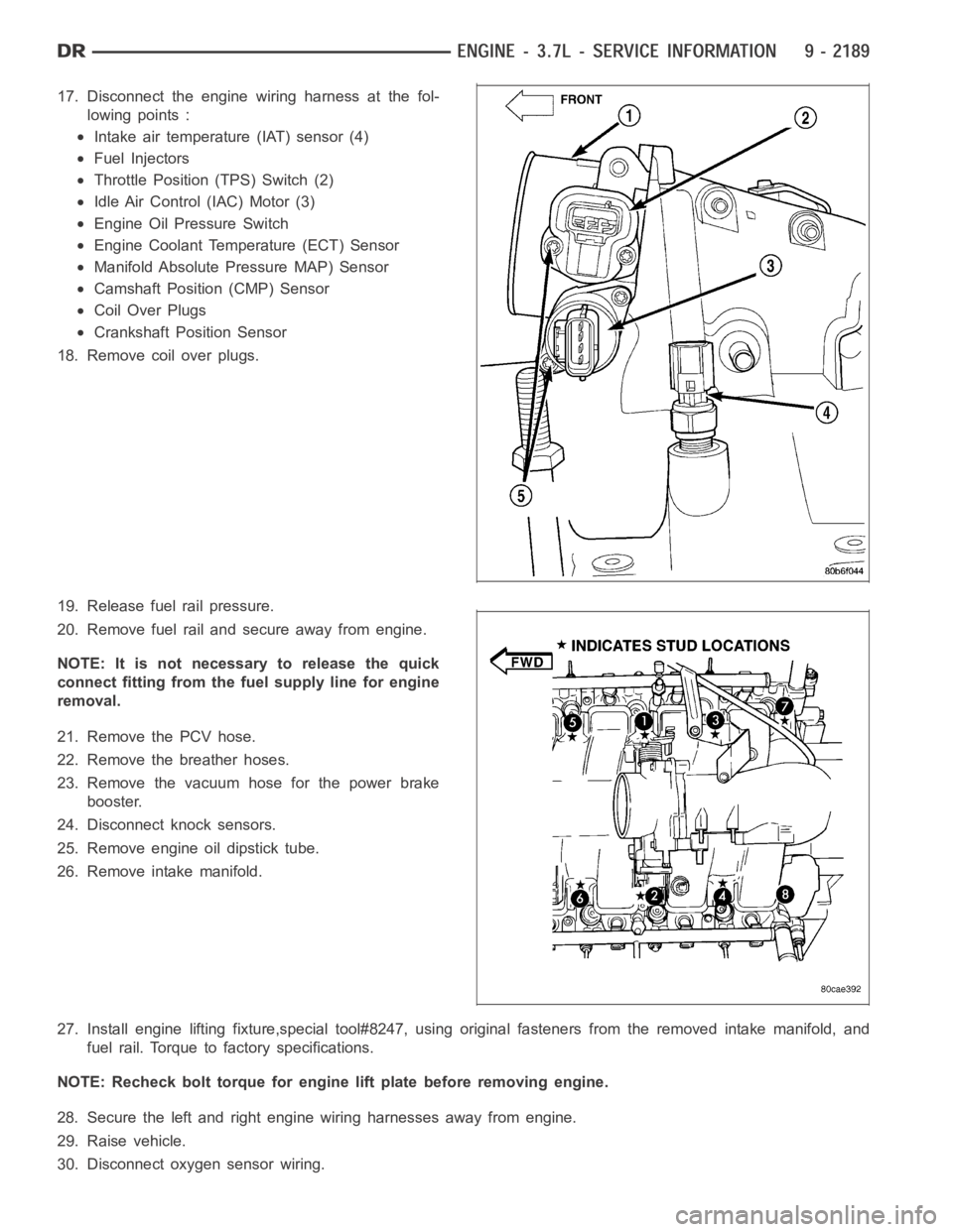
17. Disconnect the engine wiring harness at the fol-
lowing points :
Intake air temperature (IAT) sensor (4)
Fuel Injectors
Throttle Position (TPS) Switch (2)
Idle Air Control (IAC) Motor (3)
Engine Oil Pressure Switch
Engine Coolant Temperature (ECT) Sensor
Manifold Absolute Pressure MAP) Sensor
Camshaft Position (CMP) Sensor
Coil Over Plugs
Crankshaft Position Sensor
18. Remove coil over plugs.
19. Release fuel rail pressure.
20. Remove fuel rail and secure away from engine.
NOTE: It is not necessary to release the quick
connect fitting from the fuel supply line for engine
removal.
21. Remove the PCV hose.
22. Remove the breather hoses.
23. Remove the vacuum hose for the power brake
booster.
24. Disconnect knock sensors.
25. Remove engine oil dipstick tube.
26. Remove intake manifold.
27. Install engine lifting fixture,special tool#8247, using original fasteners from the removed intake manifold, and
fuel rail. Torque to factory specifications.
NOTE: Recheck bolt torque for engine lift plate before removing engine.
28. Secure the left and right engine wiring harnesses away from engine.
29. Raise vehicle.
30. Disconnect oxygen sensor wiring.
Page 1502 of 5267
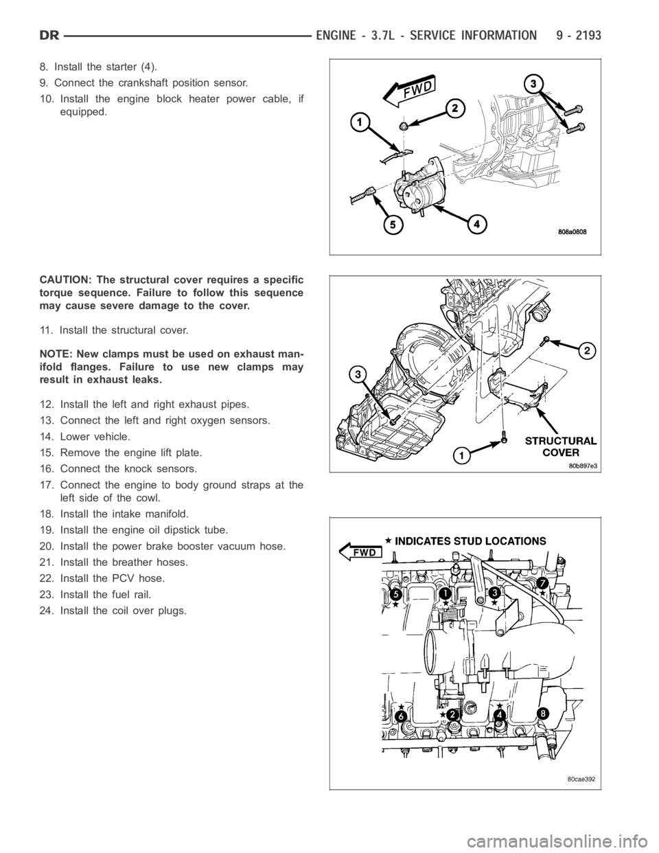
8. Install the starter (4).
9. Connect the crankshaft position sensor.
10. Install the engine block heater power cable, if
equipped.
CAUTION: The structural cover requires a specific
torque sequence. Failure to follow this sequence
may cause severe damage to the cover.
11. Install the structural cover.
NOTE: New clamps must be used on exhaust man-
ifold flanges. Failure to use new clamps may
result in exhaust leaks.
12. Install the left and right exhaust pipes.
13. Connect the left and right oxygen sensors.
14. Lower vehicle.
15. Remove the engine lift plate.
16. Connect the knock sensors.
17. Connect the engine to body ground straps at the
left side of the cowl.
18. Install the intake manifold.
19. Install the engine oil dipstick tube.
20. Install the power brake booster vacuum hose.
21. Install the breather hoses.
22. Install the PCV hose.
23. Install the fuel rail.
24. Install the coil over plugs.