brake DODGE RAM SRT-10 2006 Service Repair Manual
[x] Cancel search | Manufacturer: DODGE, Model Year: 2006, Model line: RAM SRT-10, Model: DODGE RAM SRT-10 2006Pages: 5267, PDF Size: 68.7 MB
Page 2358 of 5267
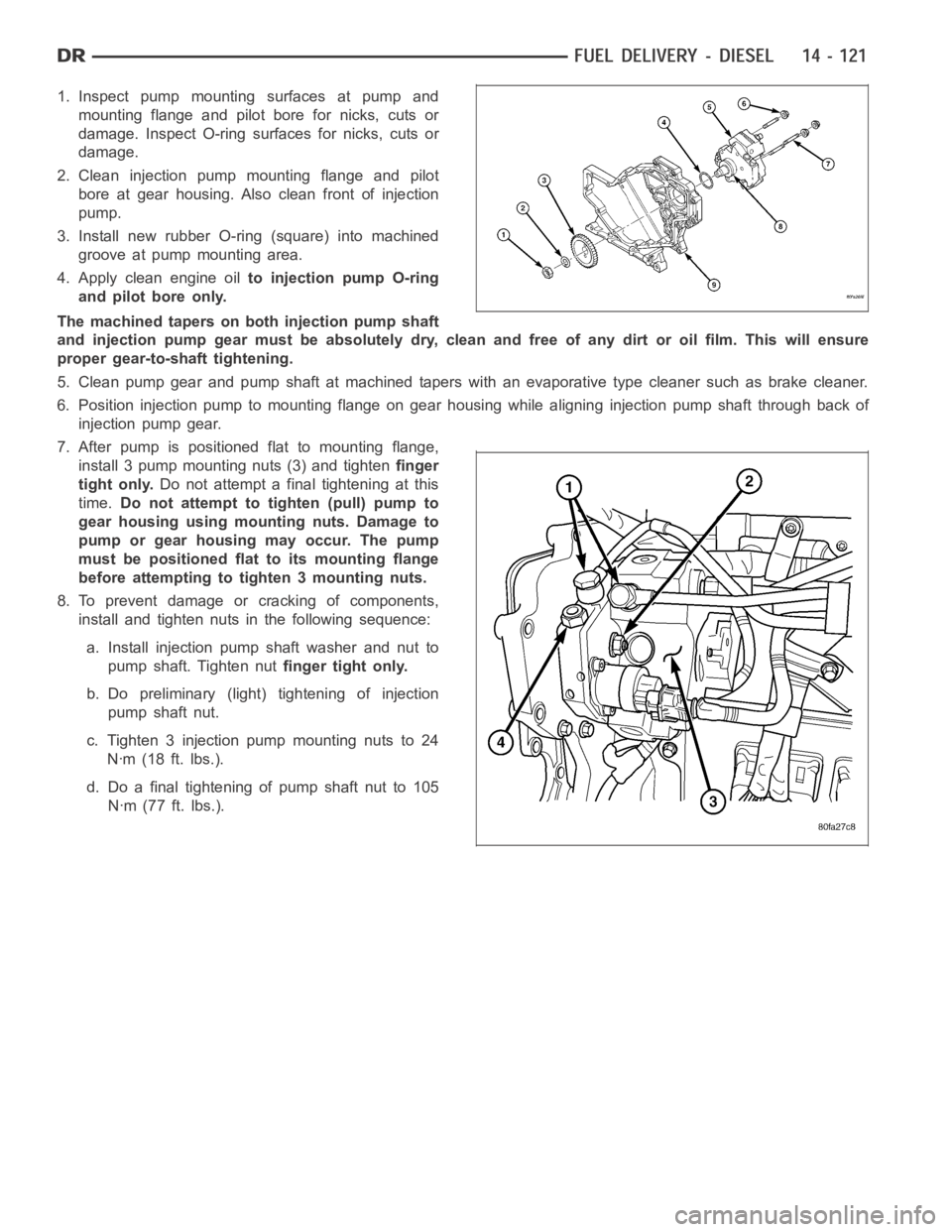
1. Inspect pump mounting surfaces at pump and
mounting flange and pilot bore for nicks, cuts or
damage. Inspect O-ring surfaces for nicks, cuts or
damage.
2. Clean injection pump mounting flange and pilot
bore at gear housing. Also clean front of injection
pump.
3. Install new rubber O-ring (square) into machined
groove at pump mounting area.
4. Apply clean engine oilto injection pump O-ring
and pilot bore only.
The machined tapers on both injection pump shaft
and injection pump gear must be absolutely dry, clean and free of any dirt oroil film. This will ensure
proper gear-to-shaft tightening.
5. Clean pump gear and pump shaft at machined tapers with an evaporative type cleaner such as brake cleaner.
6. Position injection pump to mounting flange on gear housing while aligning injection pump shaft through back of
injection pump gear.
7. After pump is positioned flat to mounting flange,
install 3 pump mounting nuts (3) and tightenfinger
tight only.Do not attempt a final tightening at this
time.Do not attempt to tighten (pull) pump to
gear housing using mounting nuts. Damage to
pump or gear housing may occur. The pump
must be positioned flat to its mounting flange
before attempting to tighten 3 mounting nuts.
8. To prevent damage or cracking of components,
install and tighten nuts in the following sequence:
a. Install injection pump shaft washer and nut to
pump shaft. Tighten nutfinger tight only.
b. Do preliminary (light) tightening of injection
pump shaft nut.
c. Tighten 3 injection pump mounting nuts to 24
Nꞏm (18 ft. lbs.).
d. Do a final tightening of pump shaft nut to 105
Nꞏm (77 ft. lbs.).
Page 2409 of 5267
INSUFFICIENT ASST. OR POOR RETURN TO CENTER
CONDITION POSSIBLE CAUSE CORRECTION
HARD TURNING OR MOMENTARY
INCREASE IN TURNING EFFORT1. Tire pressure. 1. Adjust tire pressure.
2. Low fluid level. 2. Fill to proper level.
3. Loose belt. 3. Adjust or replace.
4. Low pump pressure. 4. Pressure test and repair as
necessary.
5. Internal gear leak. 5. Replace gear.
STEERING WHEEL DOES NOT
WANT TO RETURN TO CENTER
POSITION1. Tire pressure. 1. Adjust tire pressure.
2. Wheel alignment. 2. Align front end.
3. Lack of lubrication. 3. Inspect and lubricate suspension
components.
4. High friction in steering gear. 4. Replace gear.
LOOSE STEERING AND VEHICLE LEAD
CONDITION POSSIBLE CAUSE CORRECTION
EXCESSIVE PLAY IN STEERING
WHEEL1. Worn or loose suspension or
steering components.1. Inspect and repair as necessary.
2. Worn or loose wheel bearings. 2. Inspect and repair or adjust
bearings.
3. Steering gear mounting. 3. Tighten gear mounting bolts to
specification.
4. Gear out of adjustment. 4. Replace gear.
5. Worn or loose steering coupler. 5. Inspect and replace as
necessary.
VEHICLE PULLS OR LEADS TO
ONE SIDE.1. Tire Pressure. 1. Adjust tire pressure.
2. Radial tire lead. 2. Rotate tires.
3. Brakes dragging. 3. Repair as necessary.
4. Wheel alignment. 4. Align front end.
5. Steering gear valve bias. 5. Replace steering gear.
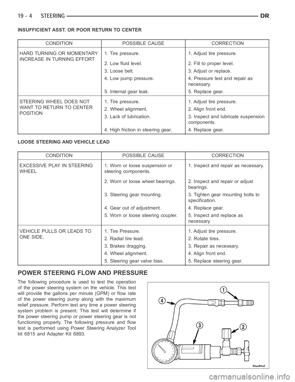
POWER STEERING FLOW AND PRESSURE
The following procedure is used to test the operation
of the power steering system on the vehicle. This test
will provide the gallons per minute (GPM) or flow rate
of the power steering pump along with the maximum
relief pressure. Perform test any time a power steering
system problem is present. This test will determine if
the power steering pump or power steering gear is not
functioning properly. The following pressure and flow
test is performed using Power Steering Analyzer Tool
kit 6815 and Adapter Kit 6893.
Page 2416 of 5267
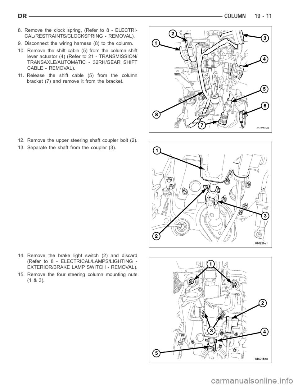
8. Remove the clock spring, (Refer to 8 - ELECTRI-
CAL/RESTRAINTS/CLOCKSPRING - REMOVAL).
9. Disconnect the wiring harness (8) to the column.
10. Remove the shift cable (5) from the column shift
lever actuator (4) (Refer to 21 - TRANSMISSION/
TRANSAXLE/AUTOMATIC - 32RH/GEAR SHIFT
CABLE - REMOVAL).
11. Release the shift cable (5) from the column
bracket (7) and remove it from the bracket.
12. Remove the upper steering shaft coupler bolt (2).
13. Separate the shaft from the coupler (3).
14. Remove the brake light switch (2) and discard
(Refer to 8 - ELECTRICAL/LAMPS/LIGHTING -
EXTERIOR/BRAKE LAMP SWITCH - REMOVAL).
15. Remove the four steering column mounting nuts
(1 & 3).
Page 2417 of 5267
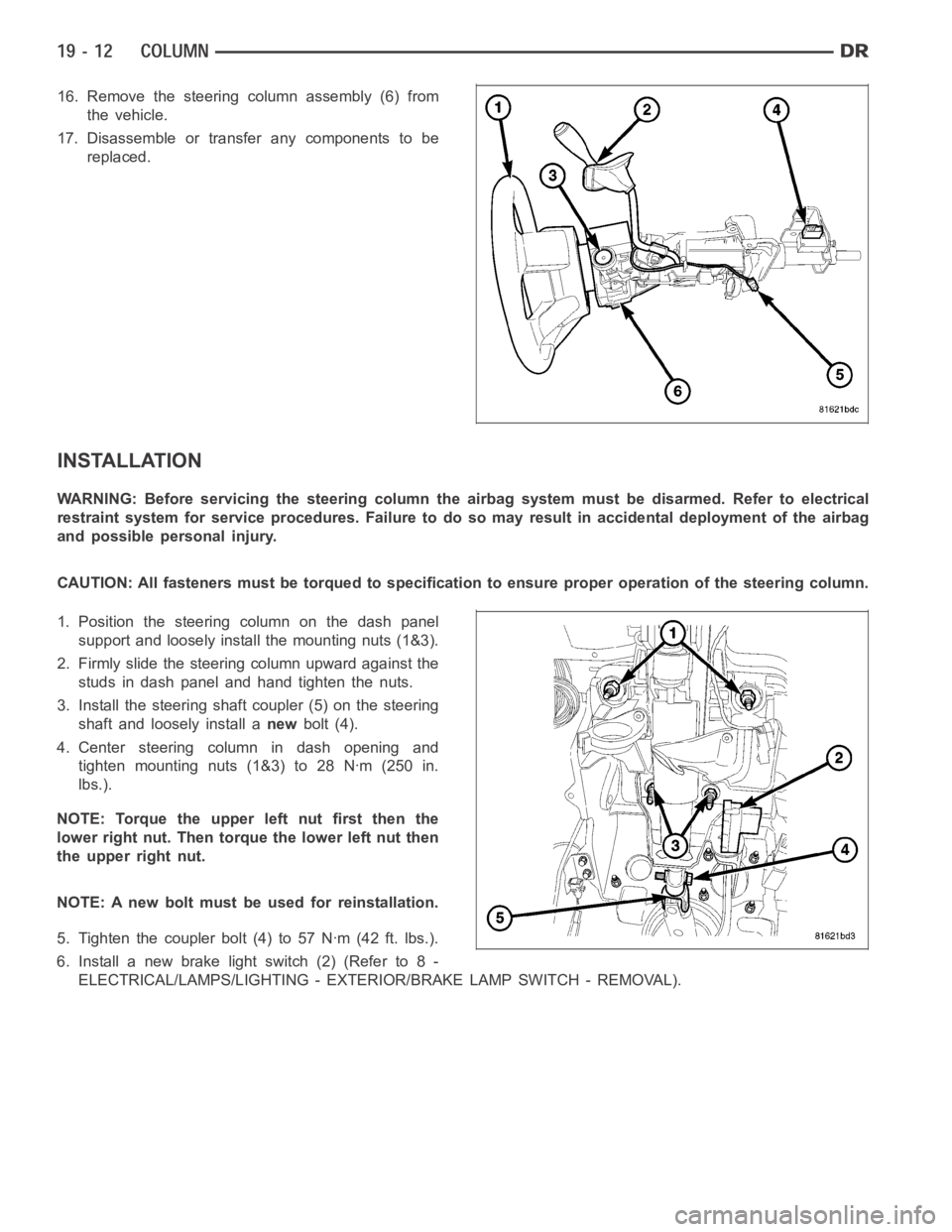
16. Remove the steering column assembly (6) from
the vehicle.
17. Disassemble or transfer any components to be
replaced.
INSTALLATION
WARNING: Before servicing the steering column the airbag system must be disarmed. Refer to electrical
restraint system for service procedures. Failure to do so may result in accidental deployment of the airbag
and possible personal injury.
CAUTION: All fasteners must be torqued to specification to ensure proper operation of the steering column.
1. Position the steering column on the dash panel
support and loosely install the mounting nuts (1&3).
2. Firmly slide the steering column upward against the
studs in dash panel and hand tighten the nuts.
3. Install the steering shaft coupler (5) on the steering
shaft and loosely install anewbolt (4).
4. Center steering column in dash opening and
tighten mounting nuts (1&3) to 28 Nꞏm (250 in.
lbs.).
NOTE: Torque the upper left nut first then the
lower right nut. Then torque the lower left nut then
the upper right nut.
NOTE: A new bolt must be used for reinstallation.
5. Tighten the coupler bolt (4) to 57 Nꞏm (42 ft. lbs.).
6. Install a new brake light switch (2) (Refer to 8 -
ELECTRICAL/LAMPS/LIGHTING - EXTERIOR/BRAKE LAMP SWITCH - REMOVAL).
Page 2420 of 5267
IGNITION SWITCH
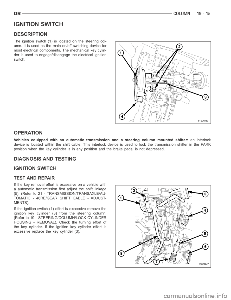
DESCRIPTION
The ignition switch (1) is located on the steering col-
umn. It is used as the main on/off switching device for
most electrical components. The mechanical key cylin-
der is used to engage/disengage the electrical ignition
switch.
OPERATION
Vehicles equipped with an automatic transmission and a steering column mounted shifter:an interlock
device is located within the shift cable. This interlock device is used to lock the transmission shifter in the PARK
position when the key cylinder is in any position and the brake pedal is not depressed.
DIAGNOSIS AND TESTING
IGNITION SWITCH
TEST AND REPAIR
If the key removal effort is excessive on a vehicle with
a automatic transmission first adjust the shift linkage
(5), (Refer to 21 - TRANSMISSION/TRANSAXLE/AU-
TOMATIC - 46RE/GEAR SHIFT CABLE - ADJUST-
MENTS).
If the ignition switch (1) effort is excessive remove the
ignition key cylinder (3) from the steering column.
(Refer to 19 - STEERING/COLUMN/LOCK CYLINDER
HOUSING - REMOVAL). Check the turning effort of
the key cylinder. If the ignition key cylinder effort is
excessive replace the key cylinder (3).
Page 2658 of 5267
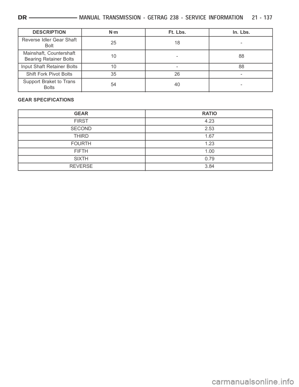
DESCRIPTION Nꞏm Ft. Lbs. In. Lbs.
Reverse Idler Gear Shaft
Bolt25 18 -
Mainshaft, Countershaft
Bearing Retainer Bolts10 - 88
Input Shaft Retainer Bolts 10 - 88
Shift Fork Pivot Bolts 35 26 -
Support Braket to Trans
Bolts54 40 -
GEAR SPECIFICATIONS
GEAR RATIO
FIRST 4.23
SECOND 2.53
THIRD 1.67
FOURTH 1.23
FIFTH 1.00
SIXTH 0.79
REVERSE 3.84
Page 2745 of 5267
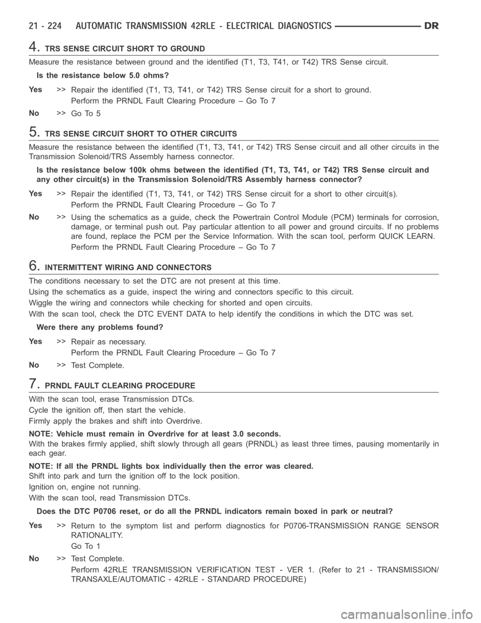
4.TRS SENSE CIRCUIT SHORT TO GROUND
Measure the resistance between ground and the identified (T1, T3, T41, or T42) TRS Sense circuit.
Is the resistance below 5.0 ohms?
Ye s>>
Repair the identified (T1, T3, T41, or T42) TRS Sense circuit for a short to ground.
Perform the PRNDL Fault Clearing Procedure – Go To 7
No>>
Go To 5
5.TRS SENSE CIRCUIT SHORT TO OTHER CIRCUITS
Measure the resistance between the identified (T1, T3, T41, or T42) TRS Sense circuit and all other circuits in the
Transmission Solenoid/TRS Assembly harness connector.
Is the resistance below 100k ohms between the identified (T1, T3, T41, or T42) TRS Sense circuit and
any other circuit(s) in the Transmission Solenoid/TRS Assembly harness connector?
Ye s>>
Repair the identified (T1, T3, T41, or T42) TRS Sense circuit for a short to other circuit(s).
Perform the PRNDL Fault Clearing Procedure – Go To 7
No>>
Using the schematics as a guide, check the Powertrain Control Module (PCM)terminals for corrosion,
damage, or terminal push out. Pay particular attention to all power and ground circuits. If no problems
are found, replace the PCM per the Service Information. With the scan tool,perform QUICK LEARN.
Perform the PRNDL Fault Clearing Procedure – Go To 7
6.INTERMITTENT WIRING AND CONNECTORS
The conditions necessary to set the DTC are not present at this time.
Using the schematics as a guide, inspect the wiring and connectors specifictothiscircuit.
Wiggle the wiring and connectors while checking for shorted and open circuits.
With the scan tool, check the DTC EVENT DATA to help identify the conditionsin which the DTC was set.
Were there any problems found?
Ye s>>
Repair as necessary.
Perform the PRNDL Fault Clearing Procedure – Go To 7
No>>
Te s t C o m p l e t e .
7.PRNDL FAULT CLEARING PROCEDURE
With the scan tool, erase Transmission DTCs.
Cycle the ignition off, then start the vehicle.
Firmly apply the brakes and shift into Overdrive.
NOTE: Vehicle must remain in Overdrive for at least 3.0 seconds.
With the brakes firmly applied, shift slowly through all gears (PRNDL) as least three times, pausing momentarily in
each gear.
NOTE: If all the PRNDL lights box individually then the error was cleared.
Shift into park and turn the ignition off to the lock position.
Ignition on, engine not running.
With the scan tool, read Transmission DTCs.
Does the DTC P0706 reset, or do all the PRNDL indicators remain boxed in parkor neutral?
Ye s>>
Return to the symptom list and perform diagnostics for P0706-TRANSMISSION RANGE SENSOR
RATIONALITY.
Go To 1
No>>
Te s t C o m p l e t e .
Perform 42RLE TRANSMISSION VERIFICATION TEST - VER 1. (Refer to 21 - TRANSMISSION/
TRANSAXLE/AUTOMATIC - 42RLE - STANDARD PROCEDURE)
Page 2765 of 5267

When Monitored:
The transmission gear ratio is monitored continuously while the transmission is in gear.
Set Condition:
If there is an excessive change in the Output RPM in any gear.
Possible Causes
(T14) OUTPUT SPEED SENSOR SIGNAL CIRCUIT OPEN
(T13) SPEED SENSOR GROUND CIRCUIT OPEN
(T14) OUTPUT SPEED SENSOR SIGNAL CIRCUIT SHORT TO GROUND
(T14) OUTPUT SPEED SENSOR SIGNAL CIRCUIT SHORT TO VOLTAGE
(T13) SPEED SENSOR GROUND CIRCUIT SHORT TO VOLTAGE
OUTPUT SPEED SENSOR
POWERTRAIN CONTROL MODULE
Always perform the Pre-Diagnostic Troubleshooting procedure before proceeding. (Refer to 21 - TRANSMIS-
SION/TRANSAXLE/AUTOMATIC - 42RLE - STANDARD PROCEDURE)
Theory of Operation
The transmission system uses two speed sensors, one to measure input RPM and one to measure output RPM.
These inputs are essential for proper transmission operation. Therefore, the integrity of this data is verified through
system checks.
Diagnostic Test
1.CHECK IF THE DTC IS CURRENT
Start the engine in park.
Raise the drive wheels off of the ground.
WARNING: Properly support the vehicle.
Firmly apply the brakes and place the transmission selector in drive.
WARNING: Be sure to keep hands and feet clear of rotating wheels.
Release the brakes and allow the drive wheels to spin freely.
NOTE: The drive wheels must be turning at this point.
With the scan tool, read the Output RPM
Is the Output RPM below 100?
Ye s>>
Go To 2
No>>
Go To 8
2.CHECK THE PCM AND WIRING USING THE TRANSMISSION SIMULATOR
Turn the ignition off to the lock position.
Remove the Ignition Switch Feed fuse from the TIPM.
CAUTION: Removal of the Ignition Switch Feed fuse from the TIPM will prevent the vehicle from being
startedingear.
WARNING: The Ignition Switch Feed fuse must be removed from the TIPM. Failure to do so can result in
personal injury or death.
Install the Transmission Simulator,Miller tool #8333 and the ElectronicTransmission Adapter kit.
Ignition on, engine not running.
With the Transmission Simulator, set the
Input/Output Speedswitch toONand the rotary switch to the3000/
1250
position.
Page 2781 of 5267

P0740-TCC OUT OF RANGE
For a complete wiring diagramRefer to Section 8W.
When Monitored:
The Torque Converter Clutch (TCC) is in FEMCC or PEMCC, Transmission temperature is hot, Engine tem-
perature is greater than 38° C or 100° F, Transmission Input Speed greater than engine speed, TPS less than
30°, and brake not applied.
Set Condition:
The TCC is modulated by controlling the duty cycle of the L/R Solenoid untilthe difference between the Engine
RPM and the Transmission Input Speed RPM or duty cycle is within a desired range. The DTC is set after the
period of 10 seconds and 3 occurrences of either: FEMCC - with slip greater than 100 RPM or PEMCC - duty
cycle greater than 85%.
Possible Causes
RELATED L/R SOLENOID OR PRESSURE SWITCH DTCS PRESENT
INTERNAL TRANSMISSION
Always perform the Pre-Diagnostic Troubleshooting procedure before proceeding. (Refer to 21 - TRANSMIS-
SION/TRANSAXLE/AUTOMATIC - 42RLE - STANDARD PROCEDURE)
Theory of Operation
When in 2nd, 3rd, or 4th gear, the torque converter clutch (TCC) can be locked or partially locked when certain
conditions are met. The TCC piston is electronically modulated by increasing the duty cycle of the LR/TCC solenoid
until the torque converter slip difference (difference between engine and turbine speed) is within 60 RPM. Then the
LR/TCC solenoid is fully energized (FEMCC / 100% duty cycle). Torque converter slip is monitored in FEMCC to
ensure adequate clutch capacity. The transmission will attempt normal EMCC operation (not in Limp-in) even after
the MIL is illuminated. MIL will illuminate after 5 minutes of accumulatedslip in FEMCC.
Diagnostic Test
1.CHECK IF RELATED DTCS ARE PRESENT
With the scan tool, read Transmission DTCs
Are the DTCs P0750 and/or P0841 present also?
Ye s>>
Refer to the Transmission category and perform the appropriate symptom.
No>>
Go To 2
2.CHECK IF THE DTC IS CURRENT
Ignition on, engine not running.
With the scan tool, record and erase DTCs.
Drive the vehicle until it is fully warmed up to at least 43° C (110° F).
Perform the following step 3 times.
Drive the vehicle at 50 mph and allow 4th gear to engage for at least 10 seconds. Close the throttle, then tip back
in until the throttle angle is between 25 and 29 degrees. Note that if you go over 30 degrees, you must back off of
the throttle and retry.
Did the TCC engage during any of the attempts?
Ye s>>
Go To 3
No>>
Perform the Hydraulic Pressure test per the Service Information and repair the internal transmission
components and Torque convertor as necessary.
Perform 42RLE TRANSMISSION VERIFICATION TEST - VER 1. (Refer to 21 - TRANSMISSION/
TRANSAXLE/AUTOMATIC - 42RLE - STANDARD PROCEDURE)
Page 2852 of 5267
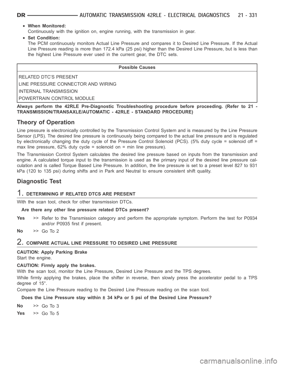
When Monitored:
Continuously with the ignition on, engine running, with the transmissionin gear.
Set Condition:
The PCM continuously monitors Actual Line Pressure and compares it to DesiredLinePressure.IftheActual
Line Pressure reading is more than 172.4 kPa (25 psi) higher than the Desired Line Pressure, but is less than
the highest Line Pressure ever used in the current gear, the DTC sets.
Possible Causes
RELATED DTC’S PRESENT
LINE PRESSURE CONNECTOR AND WIRING
INTERNAL TRANSMISSION
POWERTRAIN CONTROL MODULE
Always perform the 42RLE Pre-Diagnostic Troubleshooting procedure before proceeding. (Refer to 21 -
TRANSMISSION/TRANSAXLE/AUTOMATIC - 42RLE - STANDARD PROCEDURE)
Theory of Operation
Line pressure is electronically controlled by the Transmission Control System and is measured by the Line Pressure
Sensor (LPS). The desired line pressure is continuously being compared tothe actual line pressure and is regulated
by electronically changing the dutycycle of the Pressure Control Solenoid (PCS). (5% duty cycle = solenoid off =
max line pressure, 62% duty cycle =solenoid on = min line pressure).
The Transmission Control System calculates the desired line pressure based on inputs from the transmission and
engine. A calculated torque input to the transmission is used as the primary input of the desired line pressure cal-
culation and is called Torque Based Line Pressure. In addition, the line pressure is set to a preset level 827 to 931
kPa (120 to 135 psi) during shifts and in Park and Neutral to ensure consistent shift quality.
Diagnostic Test
1.DETERMINING IF RELATED DTCS ARE PRESENT
With the scan tool, check for other transmission DTCs.
Are there any other line pressure related DTCs present?
Ye s>>
Refer to the Transmission category and perform the appropriate symptom. Perform the test for P0934
and/or P0935 first if present.
No>>
Go To 2
2.COMPARE ACTUAL LINE PRESSURE TO DESIRED LINE PRESSURE
CAUTION: Apply Parking Brake
Start the engine.
CAUTION: Firmly apply the brakes.
With the scan tool, monitor the Line Pressure, Desired Line Pressure and the TPS degrees.
While firmly applying the brakes, place the shifter in reverse, then slowly press the accelerator pedal to a TPS
degree of 15°.
Compare the Line Pressure reading to the Desired Line Pressure reading on the scan tool.
Does the Line Pressure stay within ± 34 kPa or 5 psi of the Desired Line Pressure?
No>>
Go To 3
Ye s>>
Go To 5