brake DODGE RAM SRT-10 2006 Service Manual Online
[x] Cancel search | Manufacturer: DODGE, Model Year: 2006, Model line: RAM SRT-10, Model: DODGE RAM SRT-10 2006Pages: 5267, PDF Size: 68.7 MB
Page 1518 of 5267
7. Remove the master cylinder and booster assembly (Refer to 5 - BRAKES/HYDRAULIC/MECHANICAL/POWER
BRAKE BOOSTER - REMOVAL).
8. Remove the cylinder head cover (Refer to 9 - ENGINE/CYLINDER HEAD/CYLINDER HEAD COVER(S) -
REMOVAL).
9. Remove the fan shroud and fan blade assembly
(Refer to 7 - COOLING/ENGINE/RADIATOR FAN -
REMOVAL).
10. Remove accessory drive belt (Refer to 7 - COOL-
ING/ACCESSORY DRIVE/DRIVE BELTS -
REMOVAL).
11. Remove the power steering pump and set aside.
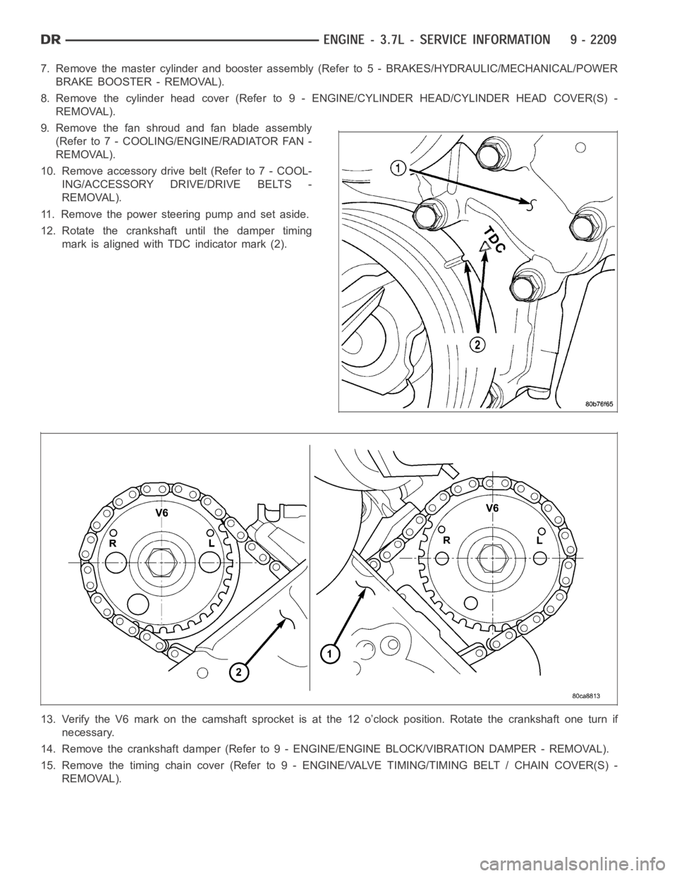
12. Rotate the crankshaft until the damper timing
mark is aligned with TDC indicator mark (2).
13. Verify the V6 mark on the camshaft sprocket is at the 12 o’clock position. Rotate the crankshaft one turn if
necessary.
14. Remove the crankshaft damper (Refer to 9 - ENGINE/ENGINE BLOCK/VIBRATION DAMPER - REMOVAL).
15. Remove the timing chain cover (Refer to 9 - ENGINE/VALVE TIMING/TIMINGBELT / CHAIN COVER(S) -
REMOVAL).
Page 1521 of 5267
2. Position the new cylinder head gasket on the locat-
ing dowels.
CAUTION: When installing cylinder head, use care
not damage the tensioner arm or the guide arm.
3. Position the cylinder head onto the cylinder block.
Make sure the cylinder head seats fully over the
locating dowels.
NOTE: The four smaller cylinder head mounting
bolts require sealant to be added to them before
installing. Failure to do so may cause leaks.
4. Lubricate the cylinder head bolt threads with clean
engine oil and install the eight M11 bolts.
5. Coat the four M8 cylinder head bolts withMopar
Lock and Seal Adhesivethen install the bolts.
NOTE: The cylinder head bolts are tightened using
an angle torque procedure, however, the bolts are
not a torque-to-yield design.
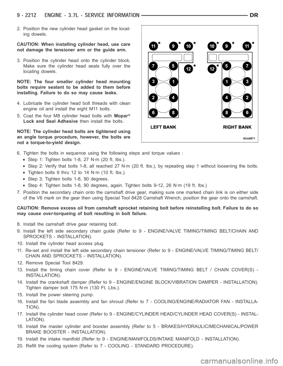
6. Tighten the bolts in sequence using the following steps and torque values:
Step 1: Tighten bolts 1-8, 27 Nꞏm (20 ft. lbs.).
Step 2: Verify that bolts 1-8, all reached 27 Nꞏm (20 ft. lbs.), by repeatingstep 1 without loosening the bolts.
Tightenbolts9thru12to14Nꞏm(10ft.lbs.).
Step 3: Tighten bolts 1-8, 90 degrees.
Step 4: Tighten bolts 1-8, 90 degrees, again. Tighten bolts 9-12, 26 Nꞏm (19ft. lbs.)
7. Position the secondary chain onto the camshaft drive gear, making sure one marked chain link is on either side
of the V6 mark on the gear then using Special Tool 8428 Camshaft Wrench, position the gear onto the camshaft.
CAUTION: Remove excess oil from camshaft sprocket retaining bolt before reinstalling bolt. Failure to do so
may cause over-torqueing of bolt resulting in bolt failure.
8. Install the camshaft drive gear retaining bolt.
9. Install the left side secondary chain guide (Refer to 9 - ENGINE/VALVE TIMING/TIMING BELT/CHAIN AND
SPROCKETS - INSTALLATION).
10. Install the cylinder head access plug.
11. Re-set and install the left side secondary chain tensioner (Refer to 9 -ENGINE/VALVE TIMING/TIMING BELT/
CHAIN AND SPROCKETS - INSTALLATION).
12. Remove Special Tool 8429.
13. Install the timing chain cover (Refer to 9 - ENGINE/VALVE TIMING/TIMING BELT / CHAIN COVER(S) -
INSTALLATION).
14. Install the crankshaft damper (Refer to 9 - ENGINE/ENGINE BLOCK/VIBRATION DAMPER - INSTALLATION).
Tighten damper bolt 175 Nꞏm (130 Ft. Lbs.).
15. Install the power steering pump.
16. Install the fan blade assembly and fan shroud (Refer to 7 - COOLING/ENGINE/RADIATOR FAN - INSTALLA-
TION).
17. Install the cylinder head cover (Refer to 9 - ENGINE/CYLINDER HEAD/CYLINDER HEAD COVER(S) - INSTAL-
LATION).
18. Install the master cylinder and booster assembly (Refer to 5 - BRAKES/HYDRAULIC/MECHANICAL/POWER
BRAKE BOOSTER - INSTALLATION).
19. Install the intake manifold (Refer to 9 - ENGINE/MANIFOLDS/INTAKE MANIFOLD - INSTALLATION).
20. Refill the cooling system (Refer to 7 - COOLING - STANDARD PROCEDURE).
Page 1601 of 5267
5. Disconnect vapor purge hose, brake booster hose, speed control servo hose, positive crankcase ventilation
(PCV) hose.
6. Disconnect generator electrical connections.
7. Disconnect air conditioning compressor electrical connections.
8. Disconnect left and right radio suppressor straps.
9. Disconnect and remove ignition coil towers.
10. Remove top oil dipstick tube retaining bolt and ground strap.
11. Bleed fuel system (Refer to 14 - FUEL SYSTEM/FUEL DELIVERY - STANDARD PROCEDURE).
12. Remove fuel rail.
13. Remove throttle body assembly and mounting bracket.
14. Drain cooling system below coolant temperature level (Refer to 7 - COOLING - STANDARD PROCEDURE).
15. Remove the heater hoses from the engine front cover and the heater core.
16. Unclip and remove heater hoses and tubes from intake manifold.
17. Remove coolant temperature sensor (Refer to 7 - COOLING/ENGINE/ENGINE COOLANT TEMP SENSOR -
REMOVAL).
18. Remove intake manifold retaining fasteners in reverse order of tightening sequence.
19. Remove intake manifold.
INSTALLATION
1. Install intake manifold gaskets.
2. Install intake manifold.
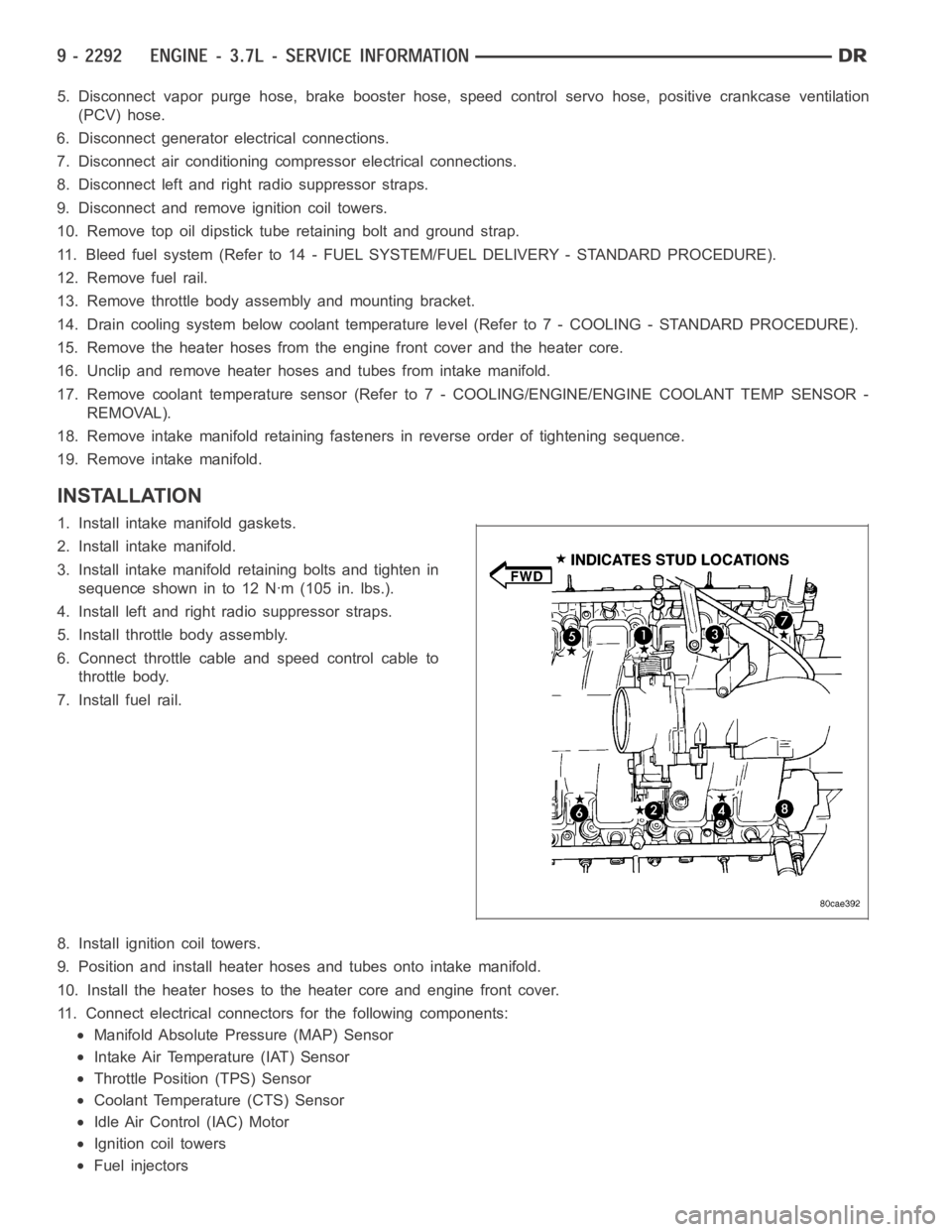
3. Install intake manifold retaining bolts and tighten in
sequence shown in to 12 Nꞏm (105 in. lbs.).
4. Install left and right radio suppressor straps.
5. Install throttle body assembly.
6. Connect throttle cable and speed control cable to
throttle body.
7. Install fuel rail.
8. Install ignition coil towers.
9. Position and install heater hoses and tubes onto intake manifold.
10. Install the heater hoses to the heater core and engine front cover.
11. Connect electrical connectors for the following components:
Manifold Absolute Pressure (MAP) Sensor
Intake Air Temperature (IAT) Sensor
Throttle Position (TPS) Sensor
Coolant Temperature (CTS) Sensor
Idle Air Control (IAC) Motor
Ignition coil towers
Fuel injectors
Page 1602 of 5267

12. Install top oil dipstick tube retaining bolt and ground strap.
13. Connect generator electrical connections.
14. Connect Vapor purge hose, Brake booster hose, Speed control servo hose, Positive crankcase ventilation
(PCV) hose.
15. Fill cooling system (Refer to 7 - COOLING - STANDARD PROCEDURE).
16. Install resonator assembly and air inlet hose.
17. Connect negative cable to battery.
Page 1654 of 5267
Install Cooling System Tester Special Tool # 7700 or equivalent to pressure cap neck. Start the engine and observe
the tester’s pressure gauge. If gauge pulsates with every power stroke of acylinder a combustion pressure leak is
evident.
CHEMICAL TEST METHOD
Combustion leaks into the cooling system can also be checked by using Bloc-Chek Kit Special Tool # C-3685-A or
equivalent. Perform test following the procedures supplied with the toolkit.
REMOVAL
REMOVAL - LEFT CYLINDER HEAD
1. Disconnect the negative cable from the battery.
2. Raise the vehicle on a hoist.
3. Disconnect the exhaust pipe at the left side
exhaust manifold.
4. Drain the engine coolant. Refer to COOLING SYS-
TEM.
5. Lower the vehicle.
6. Remove the intake manifold (Refer to 9 - ENGINE/
MANIFOLDS/INTAKE MANIFOLD - REMOVAL).
7. Remove the master cylinder and booster assembly.
Refer to section 5 brakes.
8. Remove the cylinder head cover (Refer to 9 -
ENGINE/CYLINDER HEAD/CYLINDER HEAD COVER(S) - REMOVAL).
9. Remove the fan shroud and fan blade assembly
(Refer to 7 - COOLING/ENGINE/FAN DRIVE VIS-
COUS CLUTCH - REMOVAL).
10. Remove accessory drive belt (Refer to 7 - COOL-
ING/ACCESSORY DRIVE/DRIVE BELTS -
REMOVAL).
11. Remove the power steering pump and set aside.
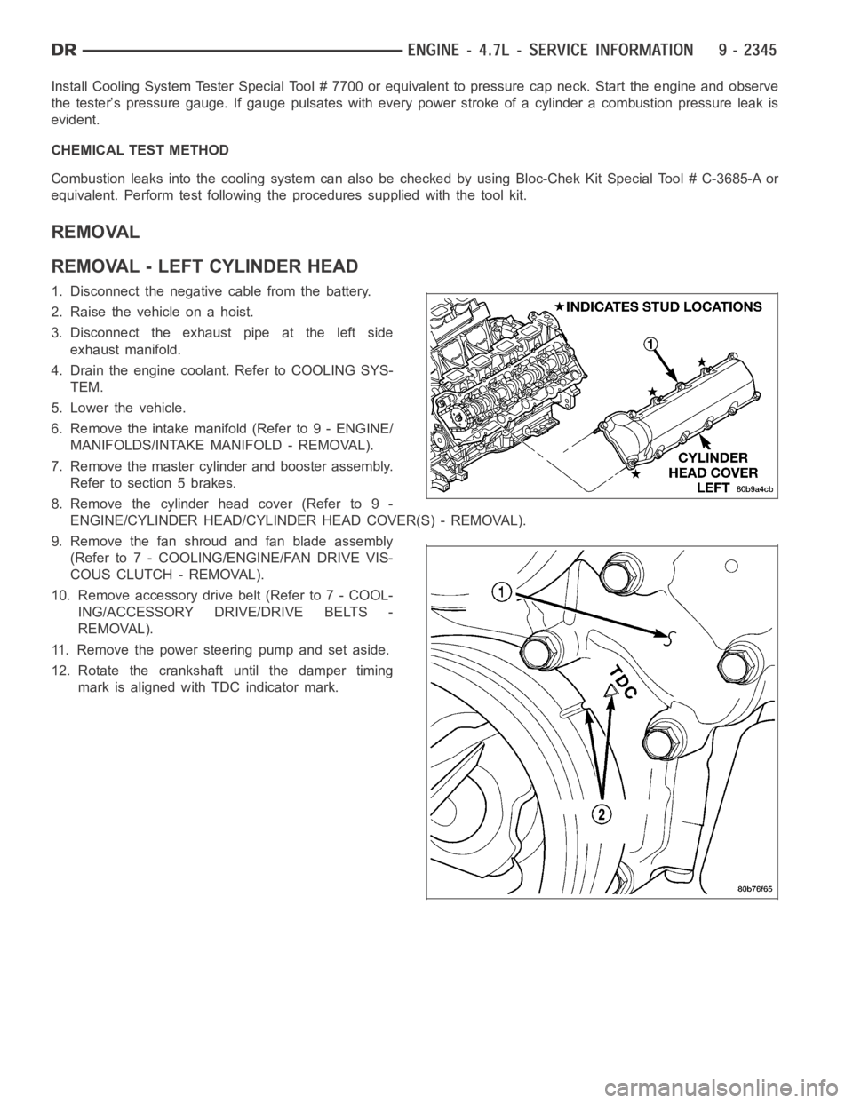
12. Rotate the crankshaft until the damper timing
mark is aligned with TDC indicator mark.
Page 1662 of 5267
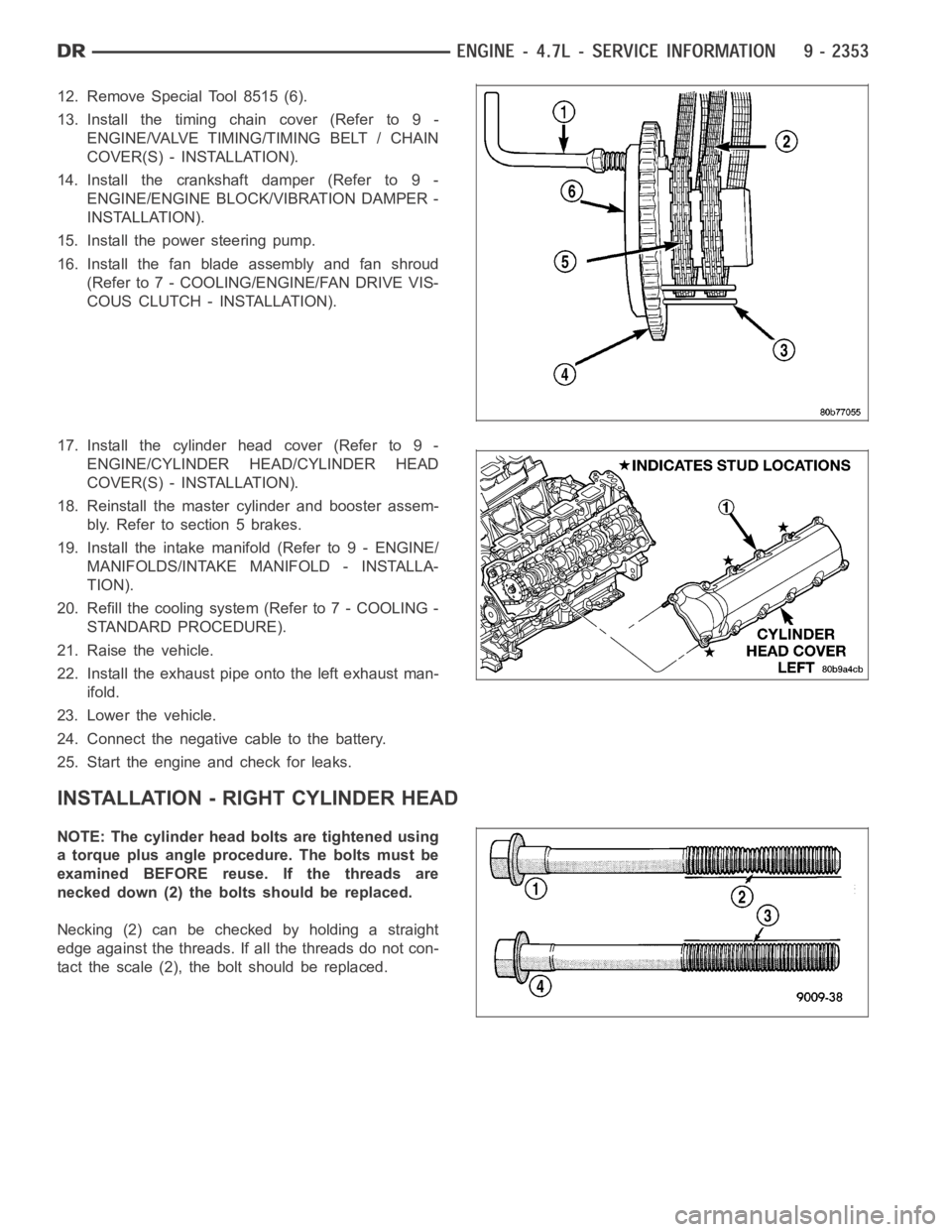
12. Remove Special Tool 8515 (6).
13. Install the timing chain cover (Refer to 9 -
ENGINE/VALVE TIMING/TIMING BELT / CHAIN
COVER(S) - INSTALLATION).
14. Install the crankshaft damper (Refer to 9 -
ENGINE/ENGINE BLOCK/VIBRATION DAMPER -
INSTALLATION).
15. Install the power steering pump.
16. Install the fan blade assembly and fan shroud
(Refer to 7 - COOLING/ENGINE/FAN DRIVE VIS-
COUS CLUTCH - INSTALLATION).
17. Install the cylinder head cover (Refer to 9 -
ENGINE/CYLINDER HEAD/CYLINDER HEAD
COVER(S) - INSTALLATION).
18. Reinstall the master cylinder and booster assem-
bly.Refertosection5brakes.
19. Install the intake manifold (Refer to 9 - ENGINE/
MANIFOLDS/INTAKE MANIFOLD - INSTALLA-
TION).
20. Refill the cooling system (Refer to 7 - COOLING -
STANDARD PROCEDURE).
21. Raise the vehicle.
22. Install the exhaust pipe onto the left exhaust man-
ifold.
23. Lower the vehicle.
24. Connect the negative cable to the battery.
25. Start the engine and check for leaks.
INSTALLATION - RIGHT CYLINDER HEAD
NOTE: The cylinder head bolts are tightened using
a torque plus angle procedure. The bolts must be
examined BEFORE reuse. If the threads are
necked down (2) the bolts should be replaced.
Necking(2)canbecheckedbyholdingastraight
edge against the threads. If all the threads do not con-
tactthescale(2),theboltshouldbereplaced.
Page 1732 of 5267
MANIFOLD - INTAKE
DESCRIPTION
The intake manifold is made of a composite material and features long runners which maximizes low end torque.
The intake manifold uses single plane sealing which consist of eight individual press in place port gaskets to prevent
leaks. Eight studs and two bolts are used to fasten the intake to the head.
DIAGNOSIS AND TESTING - INTAKE MANIFOLD LEAKAGE
An intake manifold air leak is characterized by lower than normal manifoldvacuum. Also, one or more cylinders may
not be functioning.
WARNING: USE EXTREME CAUTION WHEN THE ENGINE IS OPERATING. DO NOT STAND IN ADIRECT LINE
WITH THE FAN. DO NOT PUT YOUR HANDS NEAR THE PULLEYS, BELTS OR THE FAN. DO NOT WEAR
LOOSE CLOTHING.
1. Start the engine.
2. Spray a small stream of water at the suspected leak area.
3. If a change in RPM is observed the area of the suspected leak has been found.
4. Repair as required.
REMOVAL
1. Disconnect negative cable from battery.
2. Remove resonator assembly and air inlet hose.
3. Disconnect throttle and speed control cables.
4. Disconnect electrical connectors for the following components:
Manifold Absolute Pressure (MAP) Sensor
Intake Air Temperature (IAT) Sensor
Throttle Position (TPS) Sensor
Coolant Temperature (CTS) Sensor
Idle Air Control (IAC) Motor
5. Disconnect brake booster hose and positive crankcase ventilation (PCV)hose.
6. Disconnect generator electrical connections.
7. Disconnect air conditioning compressor electrical connections.
8. Disconnect left and right radio suppressor straps.
9. Disconnect and remove ignition coil towers (Refer to 8 - ELECTRICAL/IGNITION CONTROL/IGNITION COIL -
REMOVAL).
10. Remove top oil dipstick tube retaining bolt and ground strap.
11. Bleed fuel system (Refer to 14 - FUEL SYSTEM/FUEL DELIVERY - STANDARD PROCEDURE).
12. Remove fuel rail (Refer to 14 - FUEL SYSTEM/FUEL DELIVERY/FUEL RAIL - REMOVAL).
13. Remove throttle body assembly and mounting bracket.
14. Drain cooling system below coolant temperature level (Refer to 7 - COOLING - STANDARD PROCEDURE).
Page 1734 of 5267
INSTALLATION
1. Install intake manifold gaskets.
2. Position intake manifold.
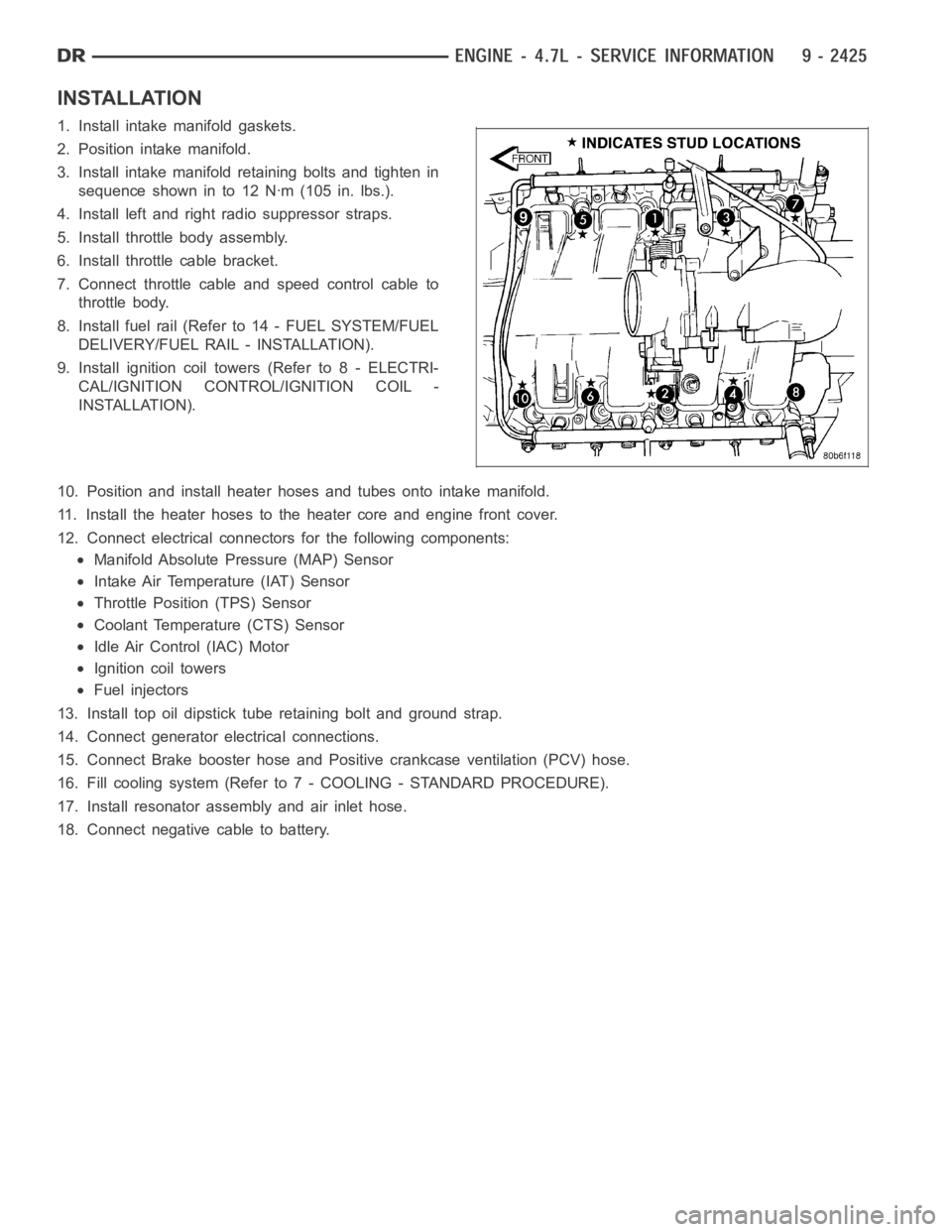
3. Install intake manifold retaining bolts and tighten in
sequence shown in to 12 Nꞏm (105 in. lbs.).
4. Install left and right radio suppressor straps.
5. Install throttle body assembly.
6. Install throttle cable bracket.
7. Connect throttle cable and speed control cable to
throttle body.
8. Install fuel rail (Refer to 14 - FUEL SYSTEM/FUEL
DELIVERY/FUEL RAIL - INSTALLATION).
9. Install ignition coil towers (Refer to 8 - ELECTRI-
CAL/IGNITION CONTROL/IGNITION COIL -
INSTALLATION).
10. Position and install heater hoses and tubes onto intake manifold.
11. Install the heater hoses to the heater core and engine front cover.
12. Connect electrical connectors for the following components:
Manifold Absolute Pressure (MAP) Sensor
Intake Air Temperature (IAT) Sensor
Throttle Position (TPS) Sensor
Coolant Temperature (CTS) Sensor
Idle Air Control (IAC) Motor
Ignition coil towers
Fuel injectors
13. Install top oil dipstick tube retaining bolt and ground strap.
14. Connect generator electrical connections.
15. Connect Brake booster hose and Positive crankcase ventilation (PCV) hose.
16. Fill cooling system (Refer to 7 - COOLING - STANDARD PROCEDURE).
17. Install resonator assembly and air inlet hose.
18. Connect negative cable to battery.
Page 1887 of 5267
MANIFOLD - INTAKE
DESCRIPTION
The intake manifold is made of a composite material and features long runners which maximizes low end torque.
The intake manifold uses single plane sealing which consist of eight individual press in place port gaskets to prevent
leaks.
DIAGNOSIS AND TESTING - INTAKE MANIFOLD LEAKAGE
An intake manifold air leak is characterized by lower than normal manifoldvacuum. Also, one or more cylinders may
not be functioning.
WARNING: USE EXTREME CAUTION WHEN THE ENGINE IS OPERATING. DO NOT STAND IN ADIRECT LINE
WITH THE FAN. DO NOT PUT YOUR HANDS NEAR THE PULLEYS, BELTS OR THE FAN. DO NOT WEAR
LOOSE CLOTHING.
1. Start the engine.
2. Spray a small stream of water at the suspected leak area.
3. If a change in RPM is observed the area of the suspected leak has been found.
4. Repair as required.
REMOVAL
1. Disconnect negative cable from battery.
2. Remove resonator assembly and air inlet hose.
3. Disconnect electrical connectors for the following components:
Manifold Absolute Pressure (MAP) Sensor
Intake Air Temperature (IAT) Sensor
Throttle Position (TPS) Sensor
Coolant Temperature (CTS) Sensor
4. Disconnect brake booster hose and positive crankcase ventilation (PCV)hose.
5. Remove generator and set aside.
NOTE: It is not necessary to remove lines or remove freon from A/C compressor.
6. Remove air conditioning compressor and set aside..
7. Bleed fuel system (Refer to 14 - FUEL SYSTEM/FUEL DELIVERY - STANDARD PROCEDURE).
8. Remove intake manifold retaining fasteners in a crisscross pattern starting from the outside bolts and ending at
themiddlebolts.
9. Remove intake manifold and IAFM as an assembly.
CLEANING
NOTE: There is NO approved repair procedure for the intake manifold. If severe damage is found during
inspection, the intake manifold must be replaced.
Before installing the intake manifoldthoroughly clean the mating surfaces. Use a suitable cleaning solvent, then air
dry.
Page 1888 of 5267
INSPECTION
1. Inspect the intake sealing surface for cracks, nicks and distortion.
2. Inspect the intake manifold vacuum hose fittings for looseness or blockage.
3. Inspect the manifold to throttlebody mating surface for cracks, nicks and distortion.
INSTALLATION
1. Install intake manifold seals.
2. Position intake manifold and IAFM.
3. Install intake manifold retaining bolts, and tighten in sequence from the middle bolts towards the outside in a
crisscross pattern. Torque fasteners to 12 Nꞏm (105 in. lbs.).
4. Connect electrical connectors for the following components:
Manifold Absolute Pressure (MAP) Sensor
Intake Air Temperature (IAT) Sensor
Throttle Position (TPS) Sensor
Coolant Temperature (CTS) Sensor
Idle Air Control (IAC) Motor
5. Install generator.
6. Install A/C compressor.
7. Connect Brake booster hose and Positive crankcase ventilation (PCV) hose.
8. Install resonator assembly and air inlet hose.
9. Connect negative cable to battery.