coolant DODGE RAM SRT-10 2006 Service Repair Manual
[x] Cancel search | Manufacturer: DODGE, Model Year: 2006, Model line: RAM SRT-10, Model: DODGE RAM SRT-10 2006Pages: 5267, PDF Size: 68.7 MB
Page 2307 of 5267

5.7L V-8
The 2-wire Intake Manifold Air Temperature (IAT) sen-
sor is installed in the intake manifold (2) with the sen-
sor element extending into the air stream.
The IAT sensor is a two-wire Negative Thermal Coef-
ficient (NTC) sensor. Meaning, as intake manifold tem-
perature increases, resistance (voltage) in the sensor
decreases. As temperature decreases, resistance
(voltage) in the sensor increases.
OPERATION
The IAT sensor provides an input voltage to the Powertrain Control Module (PCM) indicating the density of the air
entering the intake manifold based upon intake manifold temperature. At key-on, a 5–volt power circuit is supplied
to the sensor from the PCM. The sensor is grounded at the PCM through a low-noise, sensor-return circuit.
The PCM uses this input to calculate the following:
Injector pulse-width
Adjustment of spark timing (to help prevent spark knock with high intake manifold air-charge temperatures)
The resistance values of the IAT sensor is the same as for the Engine CoolantTemperature (ECT) sensor.
Page 2344 of 5267
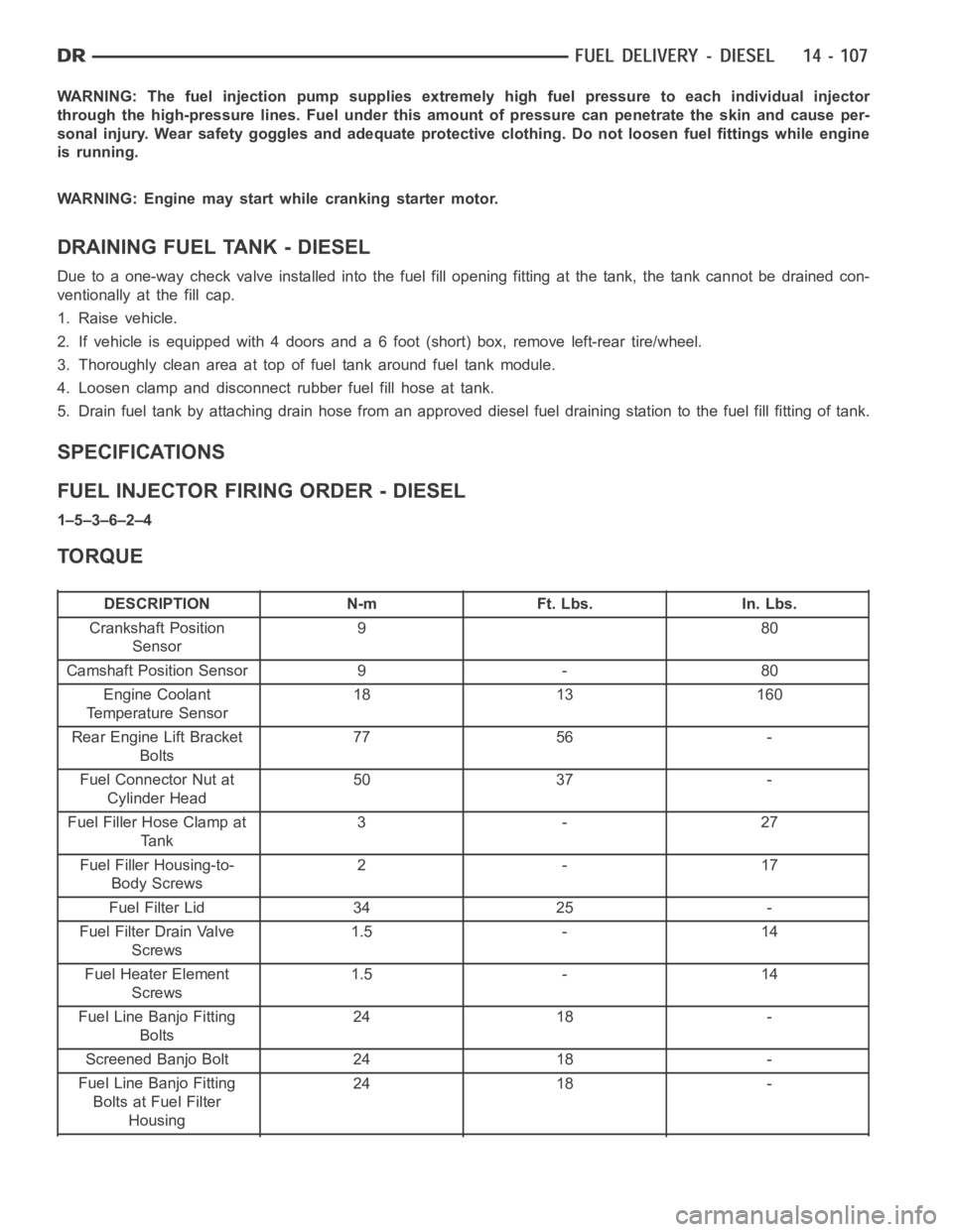
WARNING: The fuel injection pump supplies extremely high fuel pressure toeach individual injector
through the high-pressure lines. Fuel under this amount of pressure can penetrate the skin and cause per-
sonal injury. Wear safety goggles and adequate protective clothing. Do not loosen fuel fittings while engine
is running.
WARNING: Engine may start while cranking starter motor.
DRAINING FUEL TANK - DIESEL
Due to a one-way check valve installed into the fuel fill opening fitting atthe tank, the tank cannot be drained con-
ventionally at the fill cap.
1. Raise vehicle.
2. If vehicle is equipped with 4 doors and a 6 foot (short) box, remove left-rear tire/wheel.
3. Thoroughly clean area at top of fuel tank around fuel tank module.
4. Loosen clamp and disconnect rubber fuel fill hose at tank.
5. Drain fuel tank by attaching drain hose from an approved diesel fuel draining station to the fuel fill fitting of tank.
SPECIFICATIONS
FUEL INJECTOR FIRING ORDER - DIESEL
1–5–3–6–2–4
TORQUE
DESCRIPTION N-m Ft. Lbs. In. Lbs.
Crankshaft Position
Sensor980
Camshaft Position Sensor 9 - 80
Engine Coolant
Temperature Sensor18 13 160
Rear Engine Lift Bracket
Bolts77 56 -
Fuel Connector Nut at
Cylinder Head50 37 -
Fuel Filler Hose Clamp at
Ta n k3-27
Fuel Filler Housing-to-
Body Screws2-17
Fuel Filter Lid 34 25 -
Fuel Filter Drain Valve
Screws1.5 - 14
Fuel Heater Element
Screws1.5 - 14
Fuel Line Banjo Fitting
Bolts24 18 -
Screened Banjo Bolt 24 18 -
Fuel Line Banjo Fitting
Bolts at Fuel Filter
Housing24 18 -
Page 2502 of 5267
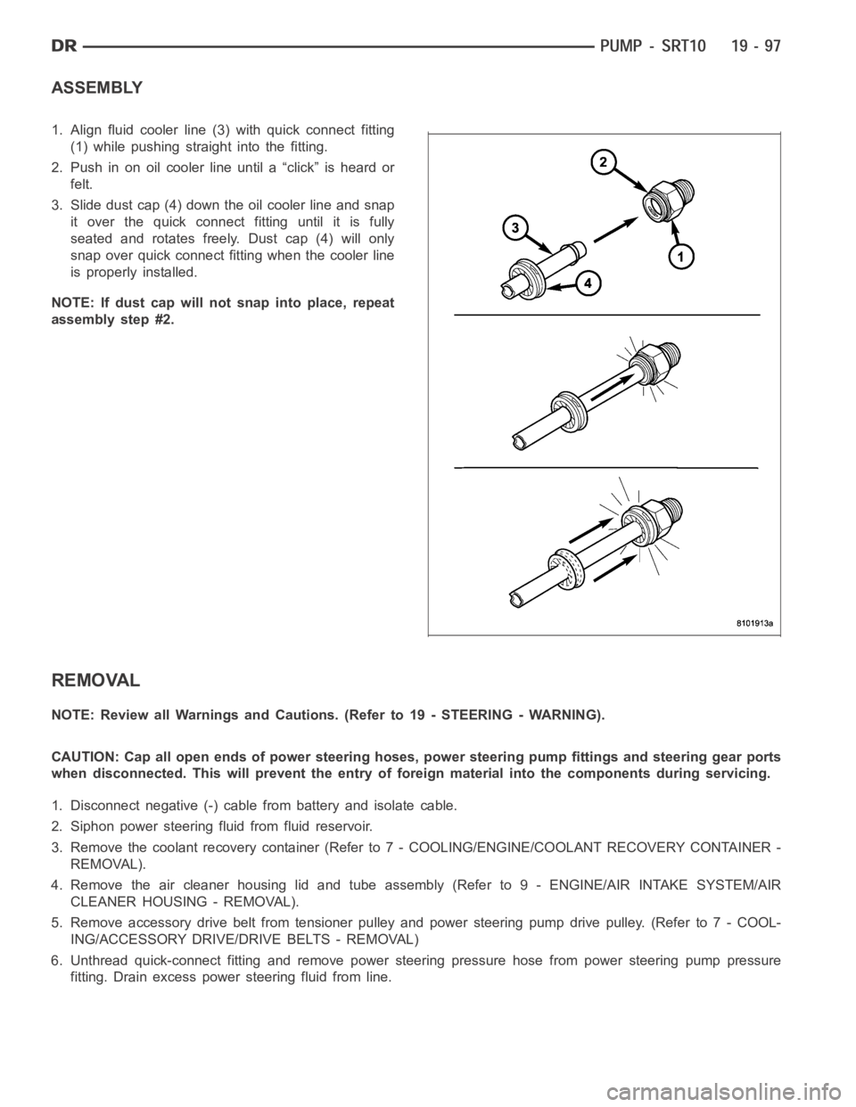
ASSEMBLY
1. Align fluid cooler line (3) with quick connect fitting
(1) while pushing straight into the fitting.
2. Push in on oil cooler line until a “click” is heard or
felt.
3. Slide dust cap (4) down the oil cooler line and snap
it over the quick connect fitting until it is fully
seated and rotates freely. Dust cap (4) will only
snap over quick connect fitting when the cooler line
is properly installed.
NOTE: If dust cap will not snap into place, repeat
assembly step #2.
REMOVAL
NOTE: Review all Warnings and Cautions. (Refer to 19 - STEERING - WARNING).
CAUTION: Cap all open ends of power steering hoses, power steering pump fittings and steering gear ports
when disconnected. This will prevent the entry of foreign material into the components during servicing.
1. Disconnect negative (-) cable from battery and isolate cable.
2. Siphon power steering fluid from fluid reservoir.
3. Remove the coolant recovery container (Refer to 7 - COOLING/ENGINE/COOLANT RECOVERY CONTAINER -
REMOVAL).
4. Remove the air cleaner housing lid and tube assembly (Refer to 9 - ENGINE/AIR INTAKE SYSTEM/AIR
CLEANER HOUSING - REMOVAL).
5. Remove accessory drive belt from tensioner pulley and power steering pump drive pulley. (Refer to 7 - COOL-
ING/ACCESSORY DRIVE/DRIVE BELTS - REMOVAL)
6. Unthread quick-connect fitting and remove power steering pressure hose from power steering pump pressure
fitting. Drain excess power steering fluid from line.
Page 2504 of 5267
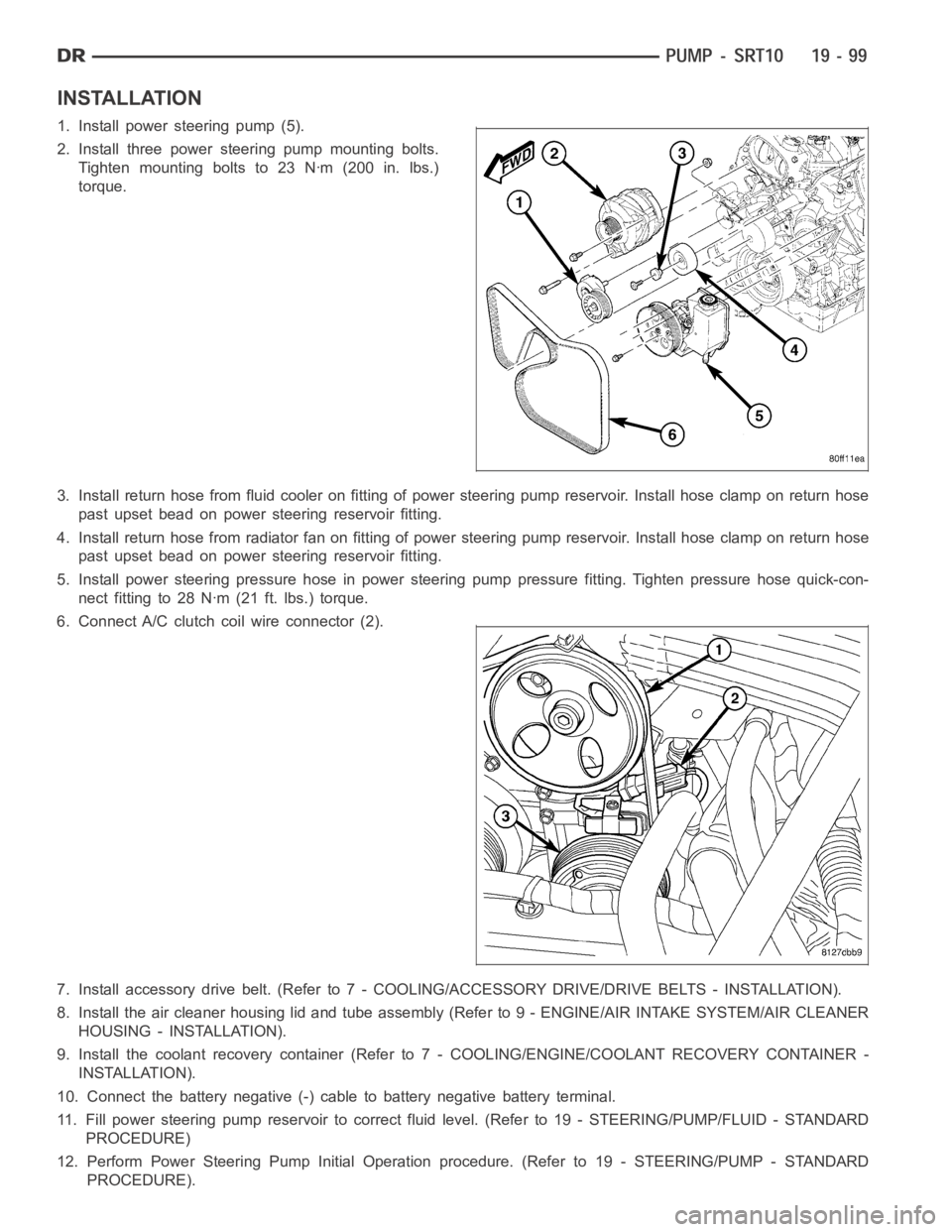
INSTALLATION
1. Install power steering pump (5).
2. Install three power steering pump mounting bolts.
Tighten mounting bolts to 23 Nꞏm (200 in. lbs.)
torque.
3. Install return hose from fluid cooler on fitting of power steering pump reservoir. Install hose clamp on return hose
past upset bead on power steering reservoir fitting.
4. Install return hose from radiator fan on fitting of power steering pump reservoir. Install hose clamp on return hose
past upset bead on power steering reservoir fitting.
5. Install power steering pressure hose in power steering pump pressure fitting. Tighten pressure hose quick-con-
nect fitting to 28 Nꞏm (21 ft. lbs.) torque.
6. Connect A/C clutch coil wire connector (2).
7. Install accessory drive belt. (Refer to 7 - COOLING/ACCESSORY DRIVE/DRIVE BELTS - INSTALLATION).
8. Install the air cleaner housing lid and tube assembly (Refer to 9 - ENGINE/AIR INTAKE SYSTEM/AIR CLEANER
HOUSING - INSTALLATION).
9. Install the coolant recovery container (Refer to 7 - COOLING/ENGINE/COOLANT RECOVERY CONTAINER -
INSTALLATION).
10. Connect the battery negative (-) cable to battery negative battery terminal.
11. Fill power steering pump reservoir to correct fluid level. (Refer to 19- STEERING/PUMP/FLUID - STANDARD
PROCEDURE)
12. Perform Power Steering Pump Initial Operation procedure. (Refer to 19- STEERING/PUMP - STANDARD
PROCEDURE).
Page 3014 of 5267
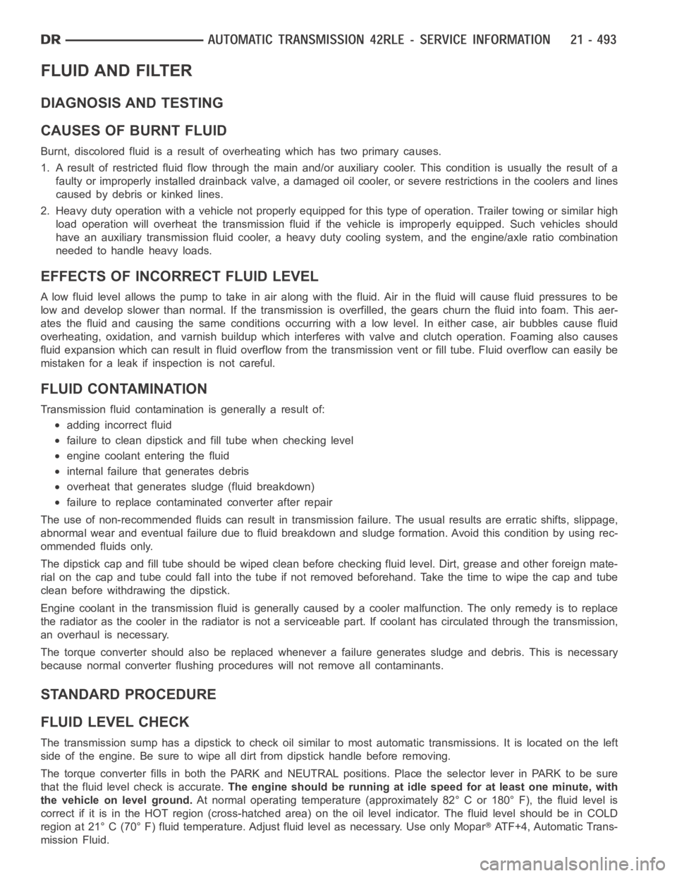
FLUID AND FILTER
DIAGNOSIS AND TESTING
CAUSES OF BURNT FLUID
Burnt, discolored fluid is a result of overheating which has two primary causes.
1. A result of restricted fluid flow through the main and/or auxiliary cooler. This condition is usually the result of a
faulty or improperly installed drainback valve, a damaged oil cooler, or severe restrictions in the coolers and lines
caused by debris or kinked lines.
2. Heavy duty operation with a vehicle not properly equipped for this type of operation. Trailer towing or similar high
load operation will overheat the transmission fluid if the vehicle is improperly equipped. Such vehicles should
have an auxiliary transmission fluid cooler, a heavy duty cooling system,and the engine/axle ratio combination
needed to handle heavy loads.
EFFECTS OF INCORRECT FLUID LEVEL
Alowfluidlevelallowsthepumptotakeinairalongwiththefluid.Airinthe fluid will cause fluid pressures to be
low and develop slower than normal. If the transmission is overfilled, thegears churn the fluid into foam. This aer-
ates the fluid and causing the same conditions occurring with a low level. In either case, air bubbles cause fluid
overheating, oxidation, and varnish buildup which interferes with valveand clutch operation. Foaming also causes
fluid expansion which can result in fluid overflow from the transmission vent or fill tube. Fluid overflow can easily be
mistaken for a leak if inspection is not careful.
FLUID CONTAMINATION
Transmission fluid contamination is generally a result of:
adding incorrect fluid
failure to clean dipstick and fill tube when checking level
engine coolant entering the fluid
internal failure that generates debris
overheat that generates sludge (fluid breakdown)
failure to replace contaminated converter after repair
The use of non-recommended fluids can result in transmission failure. Theusual results are erratic shifts, slippage,
abnormal wear and eventual failure due to fluid breakdown and sludge formation. Avoid this condition by using rec-
ommended fluids only.
The dipstick cap and fill tube should be wiped clean before checking fluid level. Dirt, grease and other foreign mate-
rial on the cap and tube could fall into the tube if not removed beforehand. Take the time to wipe the cap and tube
clean before withdrawing the dipstick.
Engine coolant in the transmission fluid is generally caused by a cooler malfunction. The only remedy is to replace
the radiator as the cooler in the radiator is not a serviceable part. If coolant has circulated through the transmission,
an overhaul is necessary.
The torque converter should also be replaced whenever a failure generatessludge and debris. This is necessary
because normal converter flushing procedures will not remove all contaminants.
STANDARD PROCEDURE
FLUID LEVEL CHECK
The transmission sump has a dipstick to check oil similar to most automatictransmissions. It is located on the left
side of the engine. Be sure to wipe all dirt from dipstick handle before removing.
The torque converter fills in both the PARK and NEUTRAL positions. Place the selector lever in PARK to be sure
that the fluid level check is accurate.The engine should be running at idle speed for at least one minute, with
the vehicle on level ground.At normal operating temperature (approximately 82° C or 180° F), the fluidlevel is
correct if it is in the HOT region (cross-hatched area) on the oil level indicator. The fluid level should be in COLD
region at 21° C (70° F) fluid temperature. Adjust fluid level as necessary.Use only Mopar
ATF+4, Automatic Trans-
mission Fluid.
Page 3067 of 5267
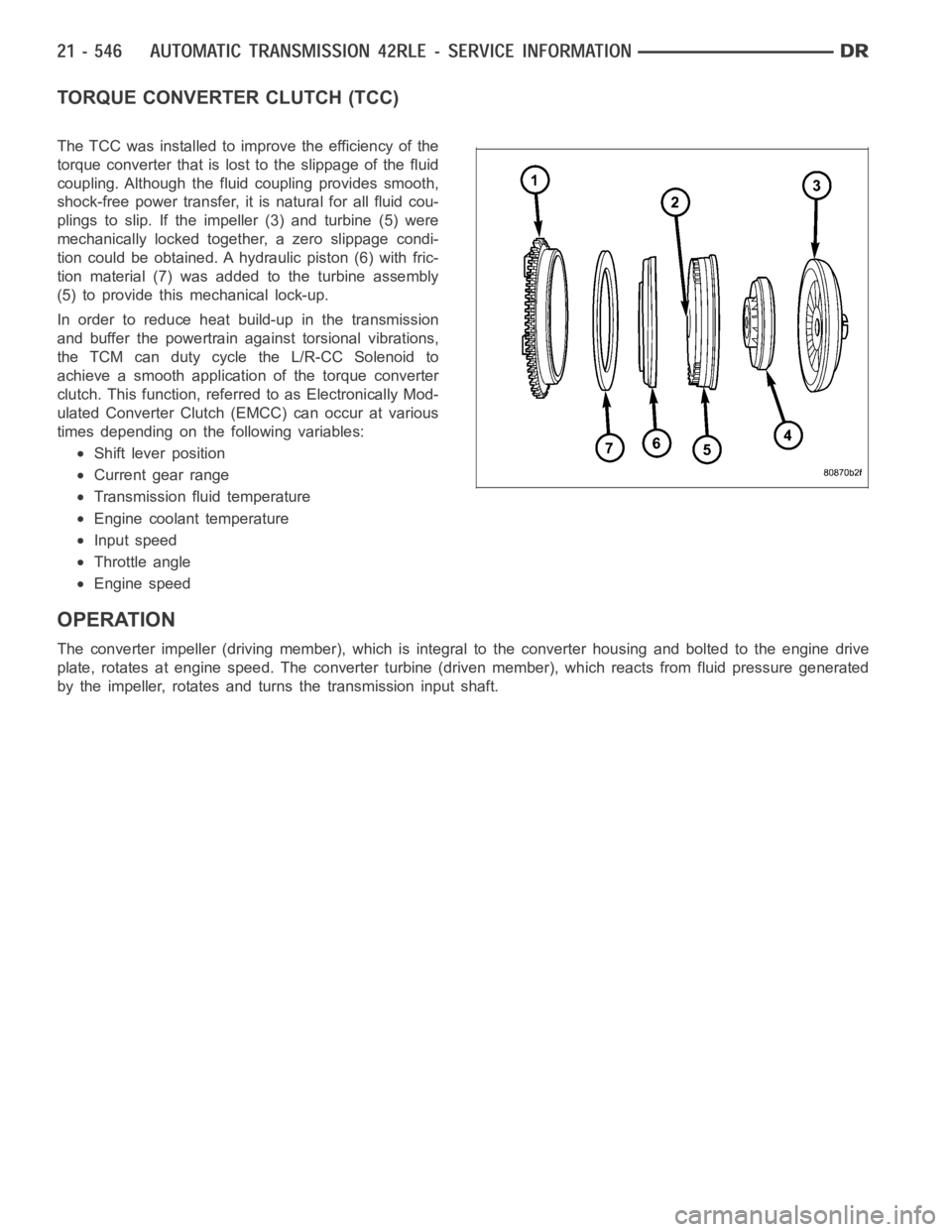
TORQUE CONVERTER CLUTCH (TCC)
The TCC was installed to improve the efficiency of the
torque converter that is lost to the slippage of the fluid
coupling. Although the fluid coupling provides smooth,
shock-free power transfer, it is natural for all fluid cou-
plings to slip. If the impeller (3) and turbine (5) were
mechanically locked together, a zero slippage condi-
tion could be obtained. A hydraulic piston (6) with fric-
tion material (7) was added to the turbine assembly
(5) to provide this mechanical lock-up.
In order to reduce heat build-up in the transmission
and buffer the powertrain against torsional vibrations,
the TCM can duty cycle the L/R-CC Solenoid to
achieve a smooth application of the torque converter
clutch. This function, referred to as Electronically Mod-
ulated Converter Clutch (EMCC) can occur at various
times depending on the following variables:
Shift lever position
Current gear range
Transmission fluid temperature
Engine coolant temperature
Input speed
Throttle angle
Engine speed
OPERATION
The converter impeller (driving member), which is integral to the converter housing and bolted to the engine drive
plate, rotates at engine speed. The converter turbine (driven member), which reacts from fluid pressure generated
by the impeller, rotates and turns the transmission input shaft.
Page 3077 of 5267
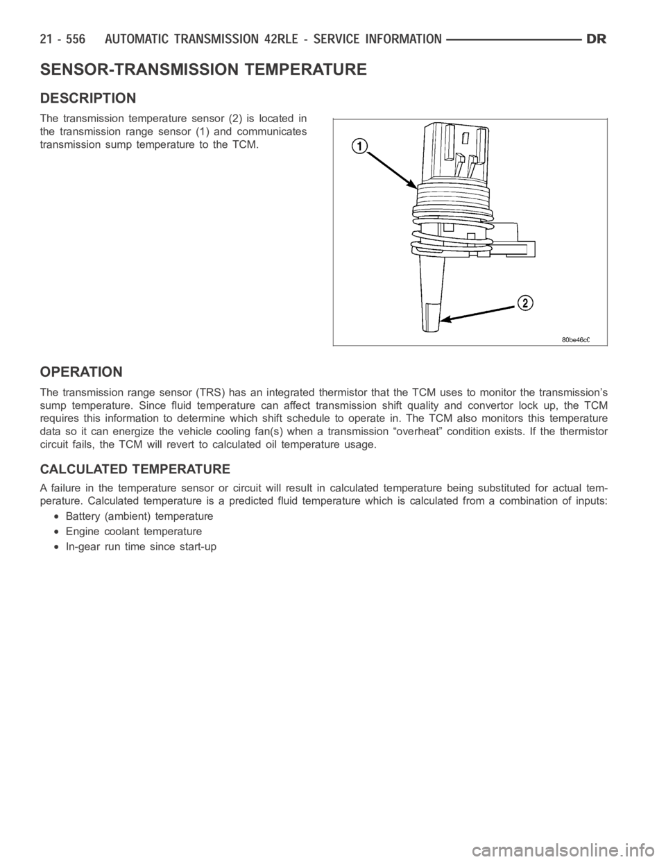
SENSOR-TRANSMISSION TEMPERATURE
DESCRIPTION
The transmission temperature sensor (2) is located in
the transmission range sensor (1) and communicates
transmission sump temperature to the TCM.
OPERATION
The transmission range sensor (TRS) has an integrated thermistor that theTCM uses to monitor the transmission’s
sump temperature. Since fluid temperature can affect transmission shiftquality and convertor lock up, the TCM
requires this information to determine which shift schedule to operate in. The TCM also monitors this temperature
data so it can energize the vehicle cooling fan(s) when a transmission “overheat” condition exists. If the thermistor
circuit fails, the TCM will revert to calculated oil temperature usage.
CALCULATED TEMPERATURE
A failure in the temperature sensor or circuit will result in calculated temperature being substituted for actual tem-
perature. Calculated temperature is a predicted fluid temperature whichis calculated from a combination of inputs:
Battery (ambient) temperature
Engine coolant temperature
In-gear run time since start-up
Page 3430 of 5267
FLUID AND FILTER
DIAGNOSIS AND TESTING
EFFECTS OF INCORRECT FLUID LEVEL
Alowfluidlevelallowsthepumptotakeinairalongwiththefluid.Airinthe fluid will cause fluid pressures to be
low and develop slower than normal. If the transmission is overfilled, thegears churn the fluid into foam. This aer-
ates the fluid and causing the same conditions occurring with a low level. In either case, air bubbles cause fluid
overheating, oxidation, and varnish buildup which interferes with valveand clutch operation. Foaming also causes
fluid expansion which can result in fluid overflow from the transmission vent or fill tube. Fluid overflow can easily be
mistaken for a leak if inspection is not careful.
CAUSES OF BURNT FLUID
Burnt, discolored fluid is a result of overheating which has three primarycauses.
1. Internal clutch slippage, usually caused by low line pressure, inadequate clutch apply pressure, or clutch seal
failure.
2. A result of restricted fluid flow through the main and/or auxiliary cooler. This condition is usually the result of a
faulty or improperly installed drainback valve, a damaged oil cooler, or severe restrictions in the coolers and lines
caused by debris or kinked lines.
3. Heavy duty operation with a vehicle not properly equipped for this type of operation. Trailer towing or similar high
load operation will overheat the transmission fluid if the vehicle is improperly equipped. Such vehicles should
have an auxiliary transmission fluid cooler, a heavy duty cooling system,and the engine/axle ratio combination
needed to handle heavy loads.
FLUID CONTAMINATION
Transmission fluid contamination is generally a result of:
adding incorrect fluid
failure to clean dipstick and fill tube when checking level
engine coolant entering the fluid
internal failure that generates debris
overheat that generates sludge (fluid breakdown)
failure to replace contaminated converter after repair
The use of non-recommended fluids can result in transmission failure. Theusual results are erratic shifts, slippage,
abnormal wear and eventual failure due to fluid breakdown and sludge formation. Avoid this condition by using rec-
ommended fluids only.
The dipstick cap and fill tube should be wiped clean before checking fluid level. Dirt, grease and other foreign mate-
rial on the cap and tube could fall into the tube if not removed beforehand. Take the time to wipe the cap and tube
clean before withdrawing the dipstick.
Engine coolant in the transmission fluid is generally caused by a cooler malfunction. The only remedy is to replace
the radiator as the cooler in the radiator is not a serviceable part. If coolant has circulated through the transmission,
an overhaul is necessary.
The torque converter should also be replaced whenever a failure generatessludge and debris. This is necessary
because normal converter flushing procedures will not remove all contaminants.
STANDARD PROCEDURE
FLUID LEVEL CHECK
Low fluid level can cause a variety of conditions because it allows the pumpto take in air along with the fluid. As
in any hydraulic system, air bubbles make the fluid spongy, therefore, pressures will be low and build up slowly.
Improper filling can also raise the fluid level too high. When the transmssion has too much fluid, the geartrain
churns up foam and cause the same conditions which occur with a low fluid level.
Page 3485 of 5267
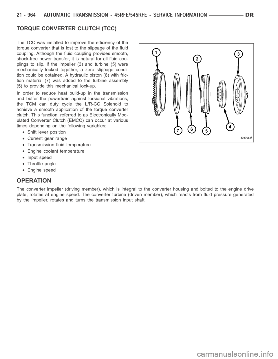
TORQUE CONVERTER CLUTCH (TCC)
The TCC was installed to improve the efficiency of the
torque converter that is lost to the slippage of the fluid
coupling. Although the fluid coupling provides smooth,
shock-free power transfer, it is natural for all fluid cou-
plings to slip. If the impeller (3) and turbine (5) were
mechanically locked together, a zero slippage condi-
tion could be obtained. A hydraulic piston (6) with fric-
tion material (7) was added to the turbine assembly
(5) to provide this mechanical lock-up.
In order to reduce heat build-up in the transmission
and buffer the powertrain against torsional vibrations,
the TCM can duty cycle the L/R-CC Solenoid to
achieve a smooth application of the torque converter
clutch. This function, referred to as Electronically Mod-
ulated Converter Clutch (EMCC) can occur at various
times depending on the following variables:
Shift lever position
Current gear range
Transmission fluid temperature
Engine coolant temperature
Input speed
Throttle angle
Engine speed
OPERATION
The converter impeller (driving member), which is integral to the converter housing and bolted to the engine drive
plate, rotates at engine speed. The converter turbine (driven member), which reacts from fluid pressure generated
by the impeller, rotates and turns the transmission input shaft.
Page 3494 of 5267
SENSOR-TRANSMISSION TEMPERATURE
DESCRIPTION
The transmission temperature sensor is a thermistor that is integral to the Transmission Range Sensor (TRS).
OPERATION
The transmission temperature sensor is used by the TCM to sense the temperature of the fluid in the sump. Since
fluid temperature can affect transmission shift quality and convertor lock up, the TCM requires this information to
determine which shift schedule to operate in.
Calculated Temperature
A failure in the temperature sensor or circuit will result in calculated temperature being substituted for actual tem-
perature. Calculated temperature is a predicted fluid temperature whichis calculated from a combination of inputs:
Battery (ambient) temperature
Engine coolant temperature
In-gear run time since start-up