DODGE RAM SRT-10 2006 Service Repair Manual
Manufacturer: DODGE, Model Year: 2006, Model line: RAM SRT-10, Model: DODGE RAM SRT-10 2006Pages: 5267, PDF Size: 68.7 MB
Page 1771 of 5267
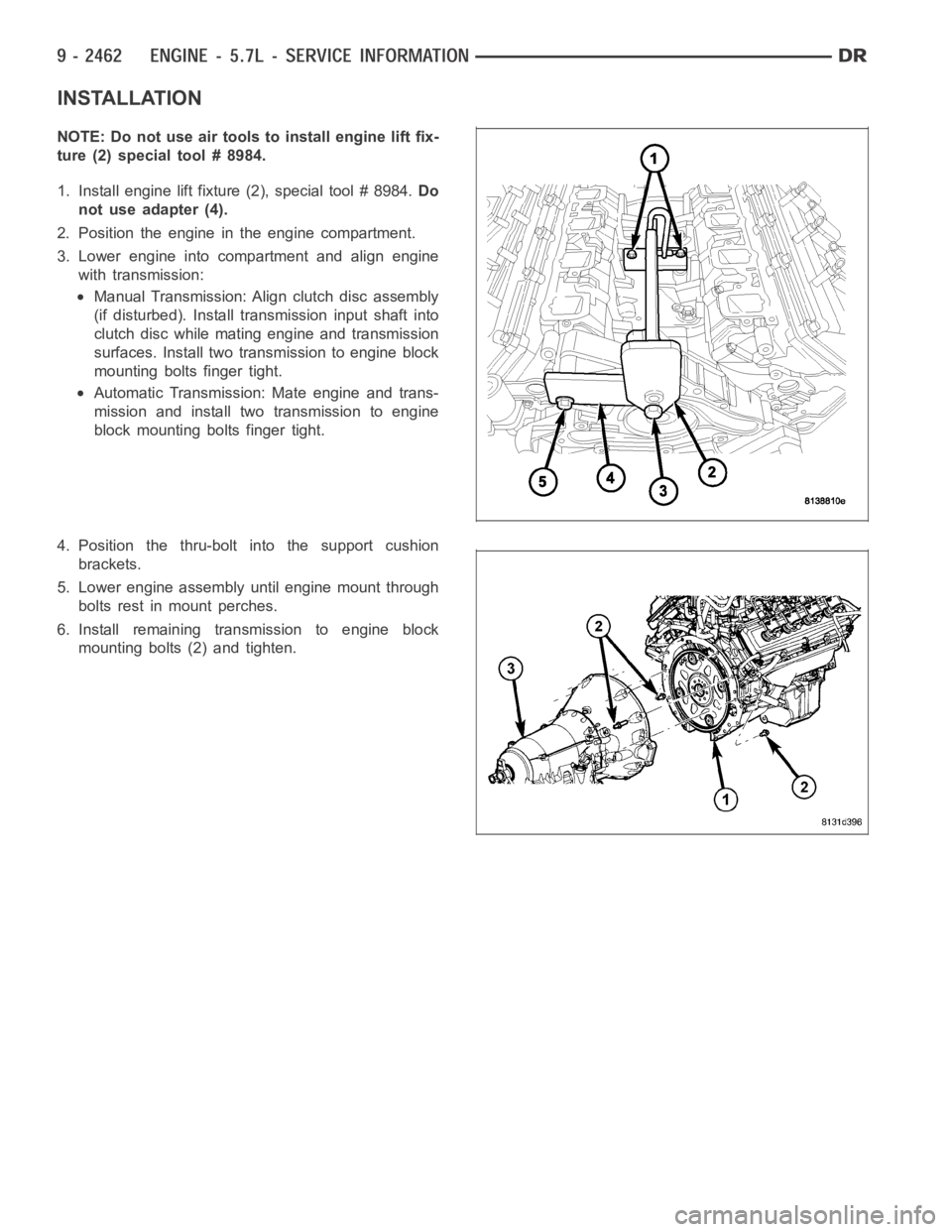
INSTALLATION
NOTE: Do not use air tools to install engine lift fix-
ture (2) special tool # 8984.
1. Install engine lift fixture (2), special tool # 8984.Do
not use adapter (4).
2. Position the engine in the engine compartment.
3. Lower engine into compartment and align engine
with transmission:
Manual Transmission: Align clutch disc assembly
(if disturbed). Install transmission input shaft into
clutch disc while mating engine and transmission
surfaces. Install two transmission to engine block
mounting bolts finger tight.
Automatic Transmission: Mate engine and trans-
mission and install two transmission to engine
block mounting bolts finger tight.
4. Position the thru-bolt into the support cushion
brackets.
5. Lower engine assembly until engine mount through
bolts rest in mount perches.
6. Install remaining transmission to engine block
mounting bolts (2) and tighten.
Page 1772 of 5267
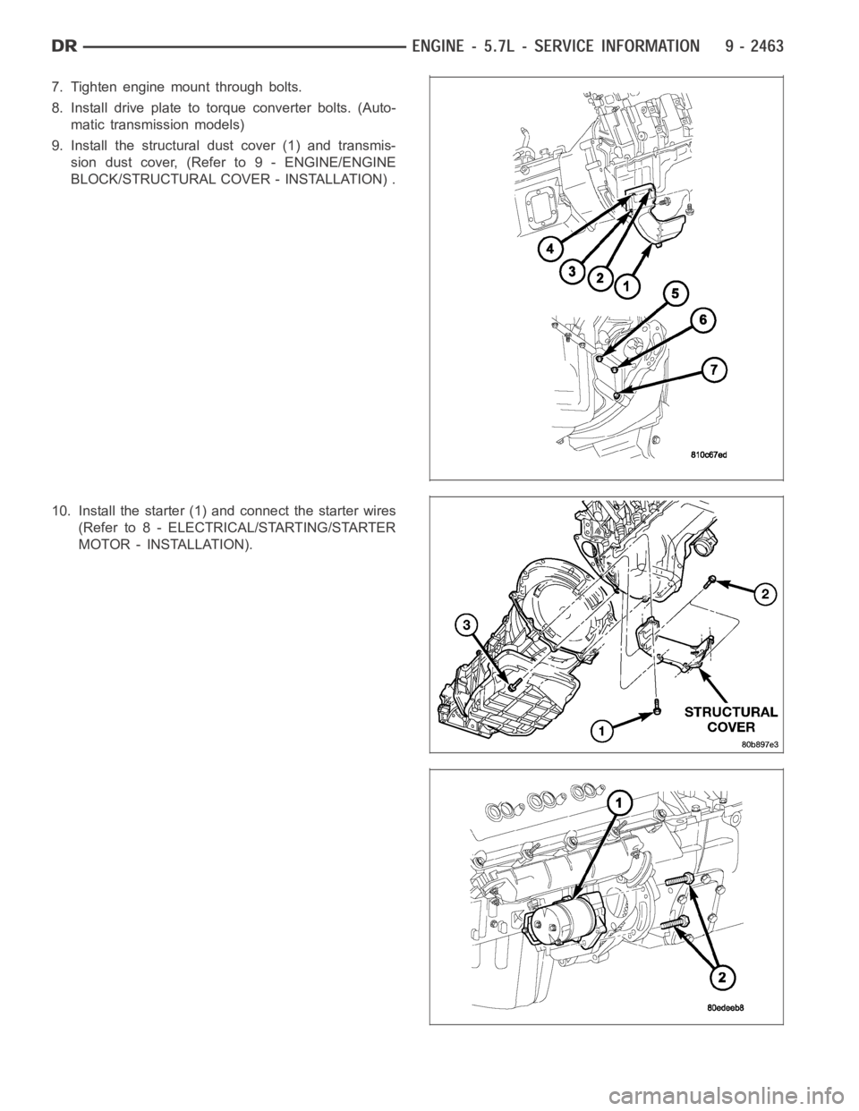
7. Tighten engine mount through bolts.
8. Install drive plate to torque converter bolts. (Auto-
matic transmission models)
9. Install the structural dust cover (1) and transmis-
sion dust cover, (Refer to 9 - ENGINE/ENGINE
BLOCK/STRUCTURAL COVER - INSTALLATION) .
10. Install the starter (1) and connect the starter wires
(Refer to 8 - ELECTRICAL/STARTING/STARTER
MOTOR - INSTALLATION).
Page 1773 of 5267
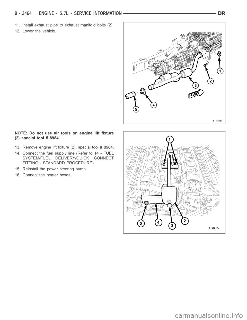
11. Install exhaust pipe to exhaust manifold bolts (2).
12. Lower the vehicle.
NOTE: Do not use air tools on engine lift fixture
(2) special tool # 8984.
13. Remove engine lift fixture (2), special tool # 8984.
14. Connect the fuel supply line (Refer to 14 - FUEL
SYSTEM/FUEL DELIVERY/QUICK CONNECT
FITTING - STANDARD PROCEDURE).
15. Reinstall the power steering pump.
16. Connect the heater hoses.
Page 1774 of 5267
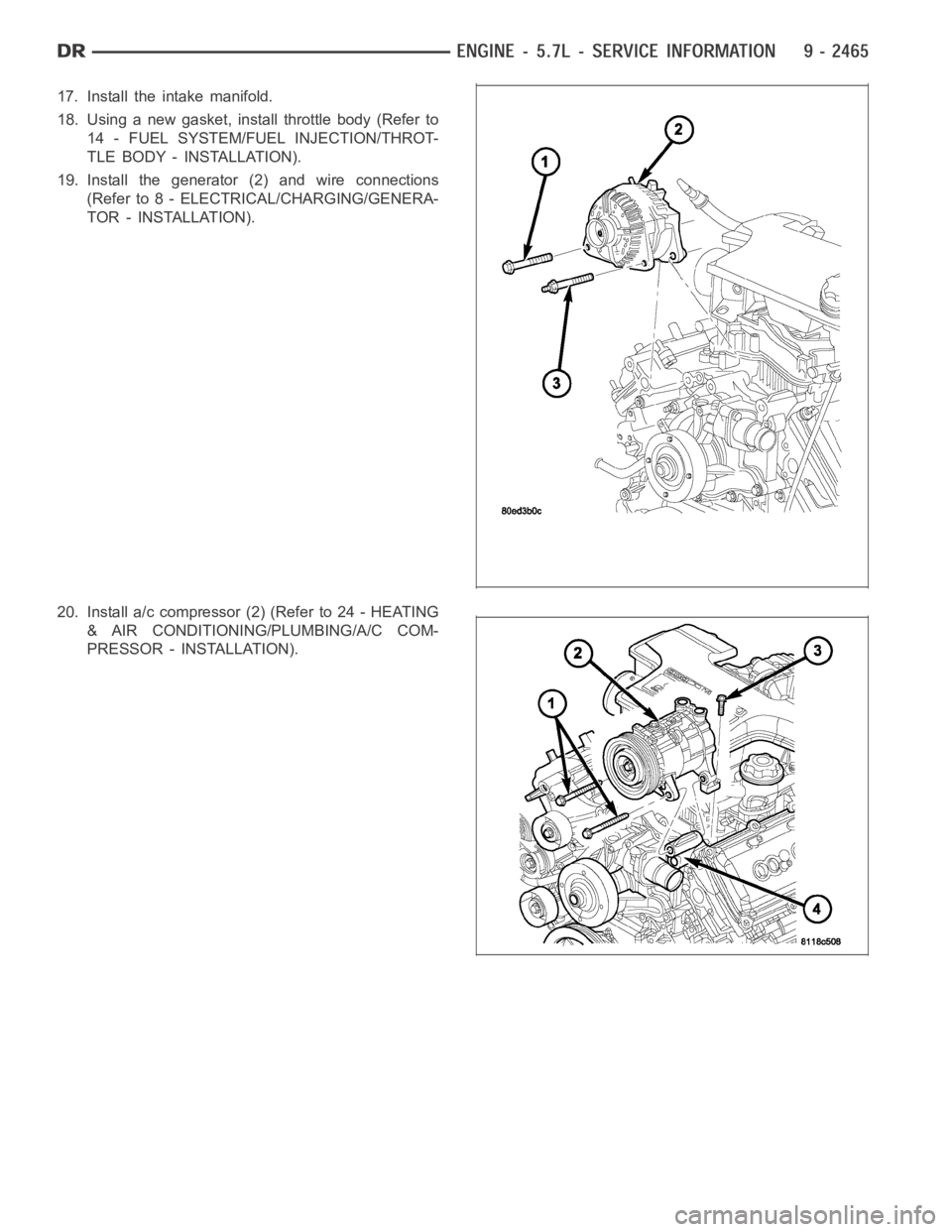
17. Install the intake manifold.
18. Using a new gasket, install throttle body (Refer to
14 - FUEL SYSTEM/FUEL INJECTION/THROT-
TLE BODY - INSTALLATION).
19. Install the generator (2) and wire connections
(Refer to 8 - ELECTRICAL/CHARGING/GENERA-
TOR - INSTALLATION).
20. Install a/c compressor (2) (Refer to 24 - HEATING
& AIR CONDITIONING/PLUMBING/A/C COM-
PRESSOR - INSTALLATION).
Page 1775 of 5267
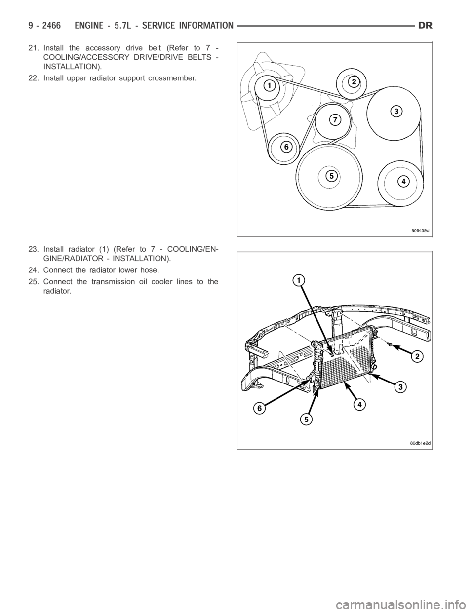
21. Install the accessory drive belt (Refer to 7 -
COOLING/ACCESSORY DRIVE/DRIVE BELTS -
INSTALLATION).
22. Install upper radiator support crossmember.
23. Install radiator (1) (Refer to 7 - COOLING/EN-
GINE/RADIATOR - INSTALLATION).
24. Connect the radiator lower hose.
25. Connect the transmission oil cooler lines to the
radiator.
Page 1776 of 5267

26. Install the fan shroud (3).
27. Install the fan (Refer to 7 - COOLING/ENGINE/
RADIATOR FAN - INSTALLATION).
28. Connect the radiator upper hose.
29. Install the washer bottle.
30. Connect the transmission cooler lines.
31. Install the air cleaner resonator and duct work..
32. Add engine oil to crankcase (Refer to LUBRICA-
TION & MAINTENANCE/FLUID TYPES - SPECI-
FICATIONS).
33. Fill cooling system (Refer to 7 - COOLING -
STANDARD PROCEDURE).
34. Connect battery negative cable.
35. Start engine and inspect for leaks.
36. Road test vehicle.
SPECIFICATIONS
5.7L ENGINE
GENERAL DESCRIPTION
DESCRIPTION SPECIFICATION
Engine Type 90° V-8 OHV
Displacement 5.7 Liters
345 ( Cubic Inches)
Bore 99.5 mm (3.91 in.)
Stroke 90.9 mm (3.58 in.)
Compression Ratio 9.6:1
Firing Order 1-8-4-3-6-5-7-2
Lubrication Pressure Feed - Full Flow
Filtration
Cooling System Liquid Cooled - Forced
Circulation
Cylinder Block Cast Iron
Cylinder Head Aluminum
Crankshaft Nodular Iron
Camshaft Hollow Assembled Camshaft
Pistons Aluminum Alloy
Connecting Rods Powdered Metal
CYLINDER BLOCK
Page 1777 of 5267
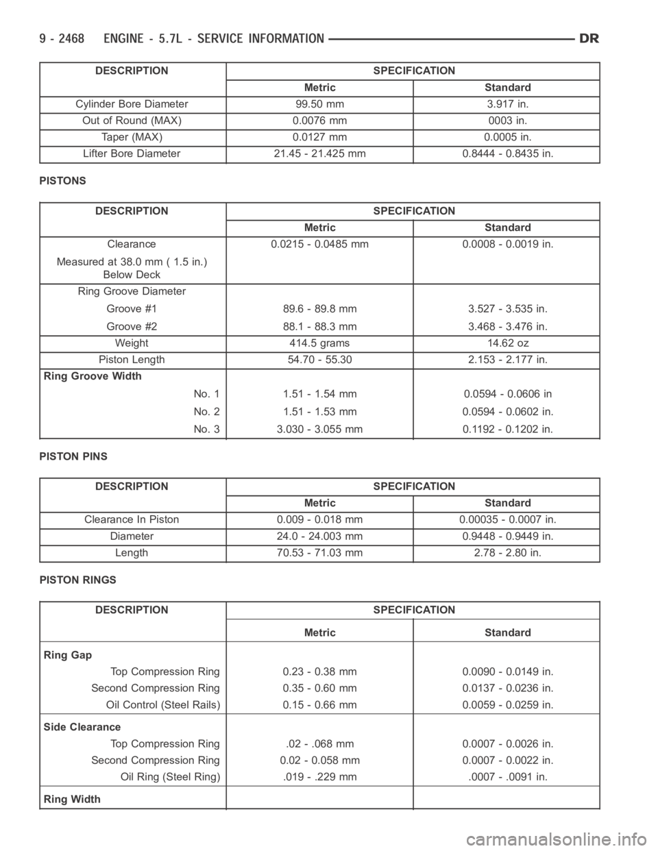
DESCRIPTION SPECIFICATION
Metric Standard
Cylinder Bore Diameter 99.50 mm 3.917 in.
Out of Round (MAX) 0.0076 mm 0003 in.
Taper (MAX) 0.0127 mm 0.0005 in.
Lifter Bore Diameter 21.45 - 21.425 mm 0.8444 - 0.8435 in.
PISTONS
DESCRIPTION SPECIFICATION
Metric Standard
Clearance 0.0215 - 0.0485 mm 0.0008 - 0.0019 in.
Measured at 38.0 mm ( 1.5 in.)
Below Deck
Ring Groove Diameter
Groove #1 89.6 - 89.8 mm 3.527 - 3.535 in.
Groove #2 88.1 - 88.3 mm 3.468 - 3.476 in.
Weight 414.5 grams 14.62 oz
Piston Length 54.70 - 55.30 2.153 - 2.177 in.
Ring Groove Width
No. 1 1.51 - 1.54 mm 0.0594 - 0.0606 in
No. 2 1.51 - 1.53 mm 0.0594 - 0.0602 in.
No. 3 3.030 - 3.055 mm 0.1192 - 0.1202 in.
PISTON PINS
DESCRIPTION SPECIFICATION
Metric Standard
Clearance In Piston 0.009 - 0.018 mm 0.00035 - 0.0007 in.
Diameter 24.0 - 24.003 mm 0.9448 - 0.9449 in.
Length 70.53 - 71.03 mm 2.78 - 2.80 in.
PISTON RINGS
DESCRIPTION SPECIFICATION
Metric Standard
Ring Gap
Top Compression Ring 0.23 - 0.38 mm 0.0090 - 0.0149 in.
Second Compression Ring 0.35 - 0.60 mm 0.0137 - 0.0236 in.
Oil Control (Steel Rails) 0.15 - 0.66 mm 0.0059 - 0.0259 in.
Side Clearance
Top Compression Ring .02 - .068 mm 0.0007 - 0.0026 in.
Second Compression Ring 0.02 - 0.058 mm 0.0007 - 0.0022 in.
Oil Ring (Steel Ring) .019 - .229 mm .0007 - .0091 in.
Ring Width
Page 1778 of 5267
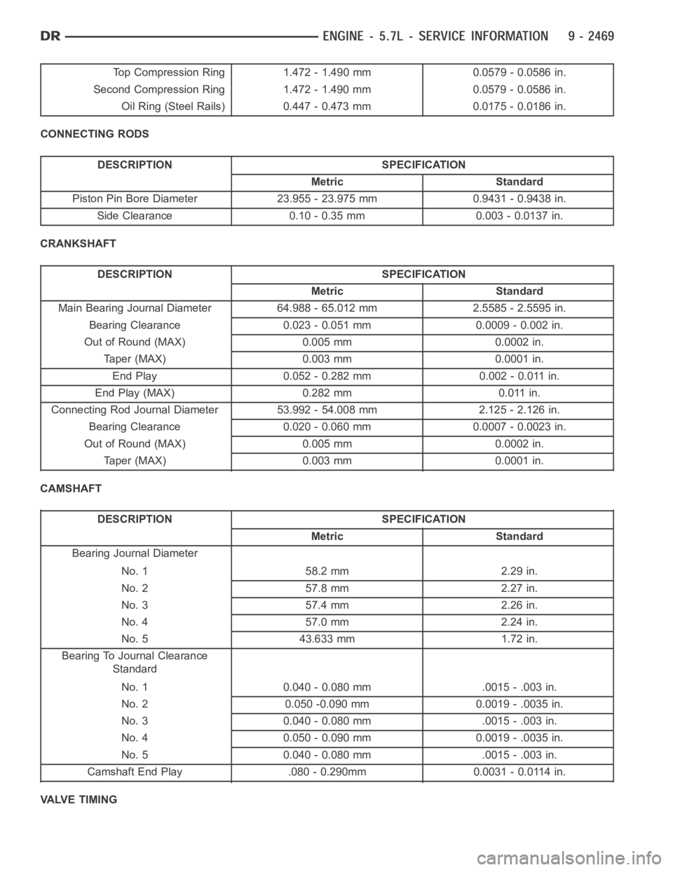
Top Compression Ring 1.472 - 1.490 mm 0.0579 - 0.0586 in.
Second Compression Ring 1.472 - 1.490 mm 0.0579 - 0.0586 in.
Oil Ring (Steel Rails) 0.447 - 0.473 mm 0.0175 - 0.0186 in.
CONNECTING RODS
DESCRIPTION SPECIFICATION
Metric Standard
Piston Pin Bore Diameter 23.955 - 23.975 mm 0.9431 - 0.9438 in.
Side Clearance 0.10 - 0.35 mm 0.003 - 0.0137 in.
CRANKSHAFT
DESCRIPTION SPECIFICATION
Metric Standard
Main Bearing Journal Diameter 64.988 - 65.012 mm 2.5585 - 2.5595 in.
Bearing Clearance 0.023 - 0.051 mm 0.0009 - 0.002 in.
Out of Round (MAX) 0.005 mm 0.0002 in.
Taper (MAX) 0.003 mm 0.0001 in.
End Play 0.052 - 0.282 mm 0.002 - 0.011 in.
End Play (MAX) 0.282 mm 0.011 in.
Connecting Rod Journal Diameter 53.992 - 54.008 mm 2.125 - 2.126 in.
Bearing Clearance 0.020 - 0.060 mm 0.0007 - 0.0023 in.
Out of Round (MAX) 0.005 mm 0.0002 in.
Taper (MAX) 0.003 mm 0.0001 in.
CAMSHAFT
DESCRIPTION SPECIFICATION
Metric Standard
Bearing Journal Diameter
No. 1 58.2 mm 2.29 in.
No. 2 57.8 mm 2.27 in.
No. 3 57.4 mm 2.26 in.
No. 4 57.0 mm 2.24 in.
No. 5 43.633 mm 1.72 in.
Bearing To Journal Clearance
Standard
No. 1 0.040 - 0.080 mm .0015 - .003 in.
No. 2 0.050 -0.090 mm 0.0019 - .0035 in.
No. 3 0.040 - 0.080 mm .0015 - .003 in.
No. 4 0.050 - 0.090 mm 0.0019 - .0035 in.
No. 5 0.040 - 0.080 mm .0015 - .003 in.
Camshaft End Play .080 - 0.290mm 0.0031 - 0.0114 in.
VALVE TIMING
Page 1779 of 5267
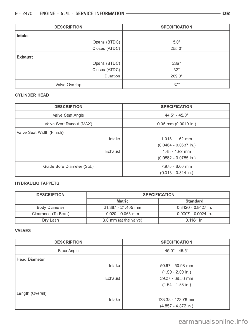
DESCRIPTION SPECIFICATION
Intake
Opens (BTDC) 5.0°
Closes (ATDC) 255.0°
Exhaust
Opens (BTDC) 236°
Closes (ATDC) 32°
Duration 269.3°
Va l v e O v e r l a p 3 7 °
CYLINDER HEAD
DESCRIPTION SPECIFICATION
Valve Seat Angle 44.5° - 45.0°
Valve Seat Runout (MAX) 0.05 mm (0.0019 in.)
Valve Seat Width (Finish)
Intake 1.018 - 1.62 mm
(0.0464 - 0.0637 in.)
Exhaust 1.48 - 1.92 mm
(0.0582 - 0.0755 in.)
Guide Bore Diameter (Std.) 7.975 - 8.00 mm
(0.313 - 0.314 in.)
HYDRAULIC TAPPETS
DESCRIPTION SPECIFICATION
Metric Standard
Body Diameter 21.387 - 21.405 mm 0.8420 - 0.8427 in.
Clearance (To Bore) 0.020 - 0.063 mm 0.0007 - 0.0024 in.
Dry Lash 3.0 mm (at the valve) 0.1181 in.
VA LV E S
DESCRIPTION SPECIFICATION
Face Angle 45.0° - 45.5°
Head Diameter
Intake 50.67 - 50.93 mm
(1.99 - 2.00 in.)
Exhaust 39.27 - 39.53 mm
(1.54 - 1.55 in.)
Length (Overall)
Intake 123.38 - 123.76 mm
(4.857 - 4.872 in.)
Page 1780 of 5267
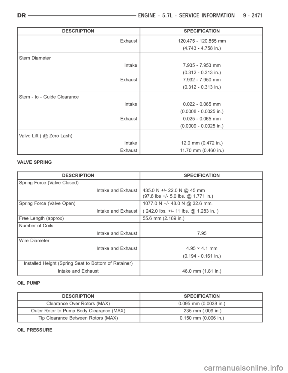
DESCRIPTION SPECIFICATION
Exhaust 120.475 - 120.855 mm
(4.743 - 4.758 in.)
Stem Diameter
Intake 7.935 - 7.953 mm
(0.312 - 0.313 in.)
Exhaust 7.932 - 7.950 mm
(0.312 - 0.313 in.)
Stem - to - Guide Clearance
Intake 0.022 - 0.065 mm
(0.0008 - 0.0025 in.)
Exhaust 0.025 - 0.065 mm
(0.0009 - 0.0025 in.)
ValveLift(@ZeroLash)
Intake 12.0 mm (0.472 in.)
Exhaust 11.70 mm (0.460 in.)
VALVE SPRING
DESCRIPTION SPECIFICATION
Spring Force (Valve Closed)
Intake and Exhaust 435.0 N +/- 22.0 N @ 45 mm
(97.8 lbs +/- 5.0 lbs. @ 1.771 in.)
Spring Force (Valve Open) 1077.0 N +/- 48.0 N @ 32.6 mm.
Intake and Exhaust ( 242.0 lbs. +/- 11 lbs. @ 1.283 in. )
Free Length (approx) 55.6 mm (2.189 in.)
Number of Coils
Intake and Exhaust 7.95
Wire Diameter
Intake and Exhaust 4.95 × 4.1 mm
(0.194 - 0.161 in.)
Installed Height (Spring Seat to Bottom of Retainer)
Intake and Exhaust 46.0 mm (1.81 in.)
OIL PUMP
DESCRIPTION SPECIFICATION
Clearance Over Rotors (MAX) 0.095 mm (0.0038 in.)
Outer Rotor to Pump Body Clearance (MAX) .235 mm (.009 in.)
Tip Clearance Between Rotors (MAX) 0.150 mm (0.006 in.)
OIL PRESSURE