DODGE RAM SRT-10 2006 Service Repair Manual
Manufacturer: DODGE, Model Year: 2006, Model line: RAM SRT-10, Model: DODGE RAM SRT-10 2006Pages: 5267, PDF Size: 68.7 MB
Page 1951 of 5267
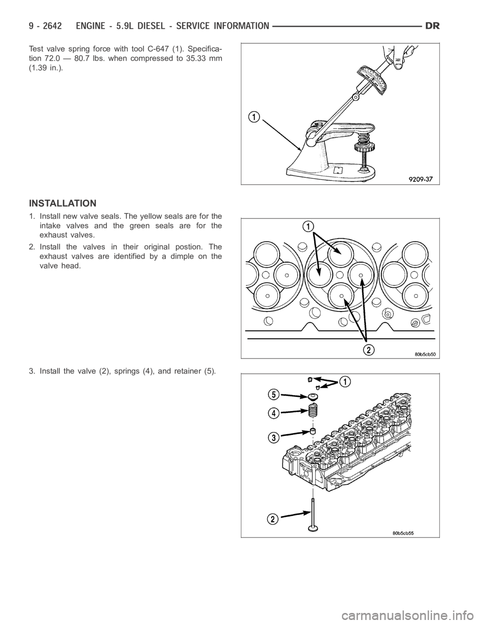
Test valve spring force with tool C-647 (1). Specifica-
tion 72.0 — 80.7 lbs. when compressed to 35.33 mm
(1.39 in.).
INSTALLATION
1. Install new valve seals. The yellow seals are for the
intake valves and the green seals are for the
exhaust valves.
2. Install the valves in their original postion. The
exhaust valves are identified by a dimple on the
valve head.
3. Install the valve (2), springs (4), and retainer (5).
Page 1952 of 5267
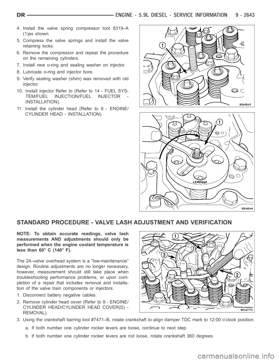
4. Install the valve spring compressor tool 8319–A
(1)as shown.
5. Compress the valve springs and install the valve
retaining locks.
6. Remove the compressor and repeat the procedure
on the remaining cylinders.
7. Install new o-ring and sealing washer on injector.
8. Lubricate o-ring and injector bore.
9. Verify sealing washer (shim) was removed with old
injector.
10. Install injector Refer to (Refer to 14 - FUEL SYS-
TEM/FUEL INJECTION/FUEL INJECTOR -
INSTALLATION).
11. Install the cylinder head (Refer to 9 - ENGINE/
CYLINDER HEAD - INSTALLATION).
STANDARD PROCEDURE - VALVE LASH ADJUSTMENT AND VERIFICATION
NOTE: To obtain accurate readings, valve lash
measurements AND adjustments should only be
performed when the engine coolant temperature is
less than 60° C (140° F).
The 24–valve overhead system is a “low-maintenance”
design. Routine adjustments are no longer necessary,
however, measurement should still take place when
troubleshooting performance problems, or upon com-
pletion of a repair that includes removal and installa-
tion of the valve train components or injectors.
1. Disconnect battery negative cables.
2. Remove cylinder head cover (Refer to 9 - ENGINE/
CYLINDER HEAD/CYLINDER HEAD COVER(S) -
REMOVAL).
3. Using the crankshaft barring tool #7471–B, rotate crankshaft to align damper TDC mark to 12:00 o’clock position.
a. If both number one cylinder rocker levers are loose, continue to next step.
b. If both number one cylinder rocker levers are not loose, rotate crankshaft 360 degrees.
Page 1953 of 5267
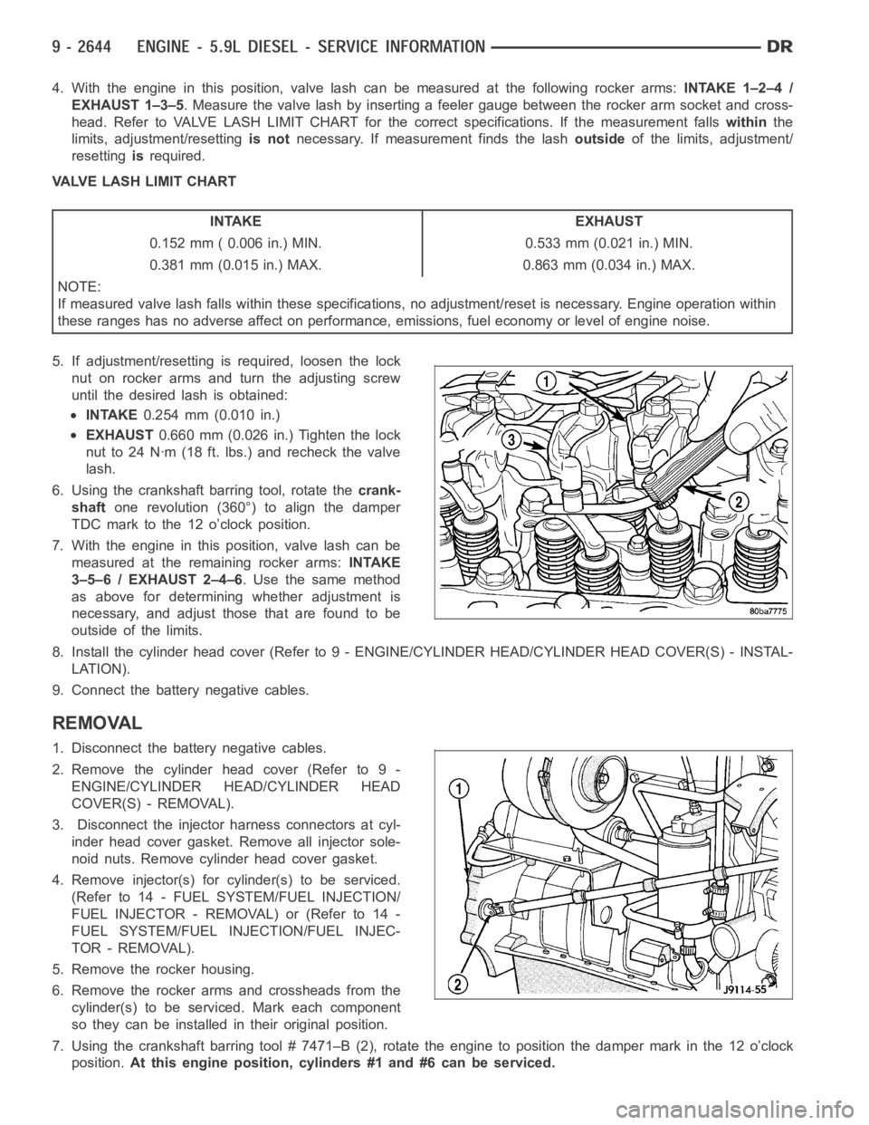
4. With the engine in this position, valve lash can be measured at the following rocker arms:INTAKE 1–2–4 /
EXHAUST 1–3–5. Measure the valve lash by inserting a feeler gauge between the rocker arm socket and cross-
head. Refer to VALVE LASH LIMIT CHART for the correct specifications. If the measurement fallswithinthe
limits, adjustment/resettingis notnecessary. If measurement finds the lashoutsideof the limits, adjustment/
resettingisrequired.
VALVE LASH LIMIT CHART
INTAKE EXHAUST
0.152 mm ( 0.006 in.) MIN. 0.533 mm (0.021 in.) MIN.
0.381 mm (0.015 in.) MAX. 0.863 mm (0.034 in.) MAX.
NOTE:
If measured valve lash falls within these specifications, no adjustment/reset is necessary. Engine operation within
these ranges has no adverse affect on performance, emissions, fuel economy or level of engine noise.
5. If adjustment/resetting is required, loosen the lock
nut on rocker arms and turn the adjusting screw
until the desired lash is obtained:
INTAKE0.254 mm (0.010 in.)
EXHAUST0.660 mm (0.026 in.) Tighten the lock
nut to 24 Nꞏm (18 ft. lbs.) and recheck the valve
lash.
6. Using the crankshaft barring tool, rotate thecrank-
shaftone revolution (360°) to align the damper
TDC mark to the 12 o’clock position.
7. With the engine in this position, valve lash can be
measured at the remaining rocker arms:INTAKE
3–5–6 / EXHAUST 2–4–6. Use the same method
as above for determining whether adjustment is
necessary, and adjust those that are found to be
outside of the limits.
8. Install the cylinder head cover (Refer to 9 - ENGINE/CYLINDER HEAD/CYLINDER HEAD COVER(S) - INSTAL-
LATION).
9. Connect the battery negative cables.
REMOVAL
1. Disconnect the battery negative cables.
2. Remove the cylinder head cover (Refer to 9 -
ENGINE/CYLINDER HEAD/CYLINDER HEAD
COVER(S) - REMOVAL).
3. Disconnect the injector harness connectors at cyl-
inder head cover gasket. Remove all injector sole-
noid nuts. Remove cylinder head cover gasket.
4. Remove injector(s) for cylinder(s) to be serviced.
(Refer to 14 - FUEL SYSTEM/FUEL INJECTION/
FUELINJECTOR-REMOVAL)or(Referto14-
FUEL SYSTEM/FUEL INJECTION/FUEL INJEC-
TOR - REMOVAL).
5. Remove the rocker housing.
6. Remove the rocker arms and crossheads from the
cylinder(s) to be serviced. Mark each component
so they can be installed in their original position.
7. Using the crankshaft barring tool # 7471–B (2), rotate the engine to position the damper mark in the 12 o’clock
position.At this engine position, cylinders #1 and #6 can be serviced.
Page 1954 of 5267
8. Remove the accessory drive belt (Refer to 7 - COOLING/ACCESSORY DRIVE/DRIVE BELTS - REMOVAL).
9. With the damper TDC mark in the 12 o’clock position, add a paint mark anywhere on the gear housing cover
next to the crankshaft damper. Place another mark on the vibration damper in alignment with the mark you just
made on the cover.
10. Divide the crankshaft damper into three equally sized segments as follows:
a. Using a tape measure, measure the circumference of the crankshaft damper and divide the measurement by
three (3).
b. Measure that distance in a counterclockwise direction from the first balancer mark and place another mark
on the balancer.
c. From the second damper mark, again measure in a counterclockwise direction and place a mark on the
damper at the same distance you measured when placing the second damper mark. The damper should
now be marked in three equally spaced locations and the damper TDC mark should be in the 12 o’clock
position.
d. Remove injectors, fuel lines, and high pressure connectors for every cylinder that requires repair.
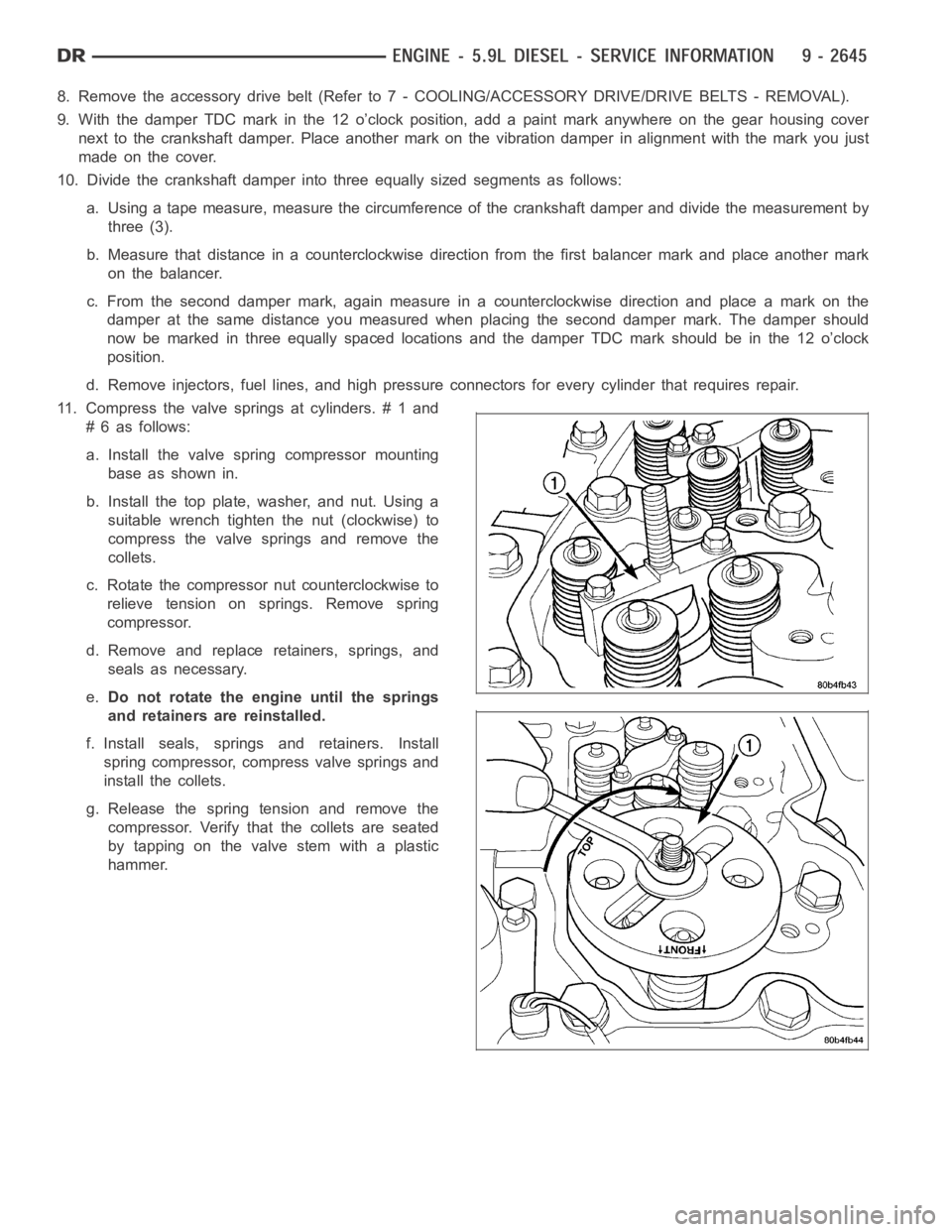
11. Compress the valve springs at cylinders. # 1 and
# 6 as follows:
a. Install the valve spring compressor mounting
base as shown in.
b. Install the top plate, washer, and nut. Using a
suitable wrench tighten the nut (clockwise) to
compress the valve springs and remove the
collets.
c. Rotate the compressor nut counterclockwise to
relieve tension on springs. Remove spring
compressor.
d. Remove and replace retainers, springs, and
seals as necessary.
e.Do not rotate the engine until the springs
and retainers are reinstalled.
f. Install seals, springs and retainers. Install
spring compressor, compress valve springs and
install the collets.
g. Release the spring tension and remove the
compressor. Verify that the collets are seated
by tapping on the valve stem with a plastic
hammer.
Page 1955 of 5267
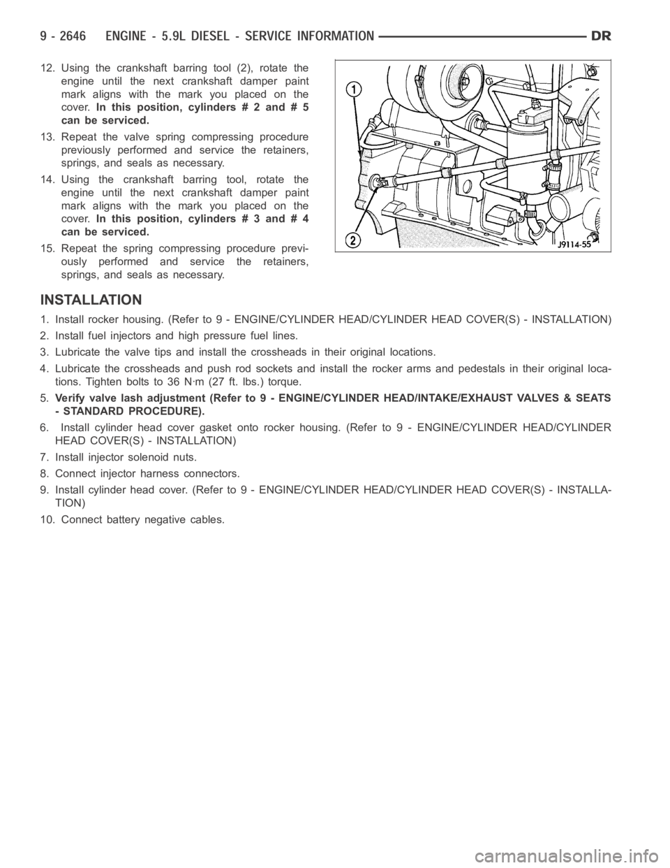
12. Using the crankshaft barring tool (2), rotate the
engine until the next crankshaft damper paint
mark aligns with the mark you placed on the
cover.In this position, cylinders # 2 and # 5
can be serviced.
13. Repeat the valve spring compressing procedure
previously performed and service the retainers,
springs, and seals as necessary.
14. Using the crankshaft barring tool, rotate the
engine until the next crankshaft damper paint
mark aligns with the mark you placed on the
cover.In this position, cylinders # 3 and # 4
can be serviced.
15. Repeat the spring compressing procedure previ-
ously performed and service the retainers,
springs, and seals as necessary.
INSTALLATION
1. Install rocker housing. (Refer to 9 -ENGINE/CYLINDER HEAD/CYLINDER HEAD COVER(S) - INSTALLATION)
2. Install fuel injectors and high pressure fuel lines.
3. Lubricate the valve tips and install the crossheads in their original locations.
4. Lubricate the crossheads and push rod sockets and install the rocker arms and pedestals in their original loca-
tions. Tighten bolts to 36 Nꞏm (27 ft. lbs.) torque.
5.Verify valve lash adjustment (Refer to 9 - ENGINE/CYLINDER HEAD/INTAKE/EXHAUST VALVES & SEATS
- STANDARD PROCEDURE).
6. Install cylinder head cover gasket onto rocker housing. (Refer to 9 - ENGINE/CYLINDER HEAD/CYLINDER
HEAD COVER(S) - INSTALLATION)
7. Install injector solenoid nuts.
8. Connect injector harness connectors.
9. Install cylinder head cover. (Refer to 9 - ENGINE/CYLINDER HEAD/CYLINDER HEAD COVER(S) - INSTALLA-
TION)
10. Connect battery negative cables.
Page 1956 of 5267
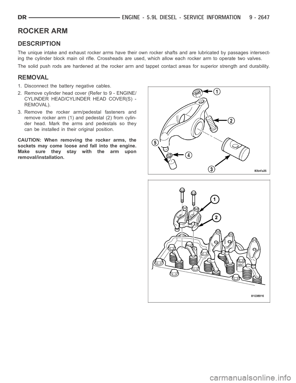
ROCKER ARM
DESCRIPTION
The unique intake and exhaust rocker arms have their own rocker shafts and are lubricated by passages intersect-
ing the cylinder block main oil rifle. Crossheads are used, which allow each rocker arm to operate two valves.
The solid push rods are hardened at the rocker arm and tappet contact areas for superior strength and durability.
REMOVAL
1. Disconnect the battery negative cables.
2. Remove cylinder head cover (Refer to 9 - ENGINE/
CYLINDER HEAD/CYLINDER HEAD COVER(S) -
REMOVAL).
3. Remove the rocker arm/pedestal fasteners and
remove rocker arm (1) and pedestal (2) from cylin-
der head. Mark the arms and pedestals so they
can be installed in their original position.
CAUTION: When removing the rocker arms, the
sockets may come loose and fall into the engine.
Make sure they stay with the arm upon
removal/installation.
Page 1957 of 5267
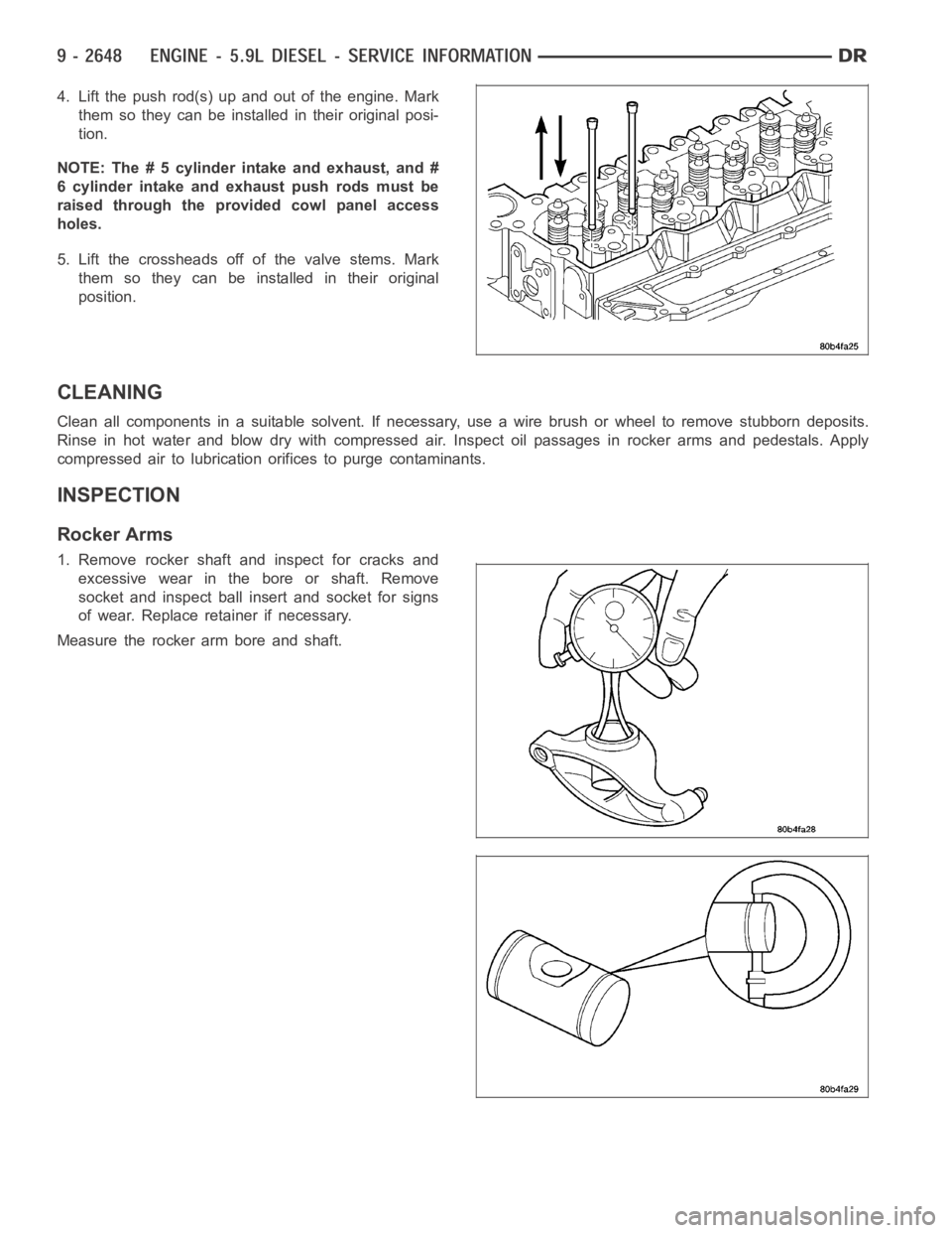
4. Lift the push rod(s) up and out of the engine. Mark
them so they can be installed in their original posi-
tion.
NOTE: The # 5 cylinder intake and exhaust, and #
6 cylinder intake and exhaust push rods must be
raised through the provided cowl panel access
holes.
5. Lift the crossheads off of the valve stems. Mark
them so they can be installed in their original
position.
CLEANING
Clean all components in a suitable solvent. If necessary, use a wire brush or wheel to remove stubborn deposits.
Rinse in hot water and blow dry with compressed air. Inspect oil passages inrocker arms and pedestals. Apply
compressed air to lubrication orifices to purge contaminants.
INSPECTION
Rocker Arms
1. Remove rocker shaft and inspect for cracks and
excessive wear in the bore or shaft. Remove
socket and inspect ball insert and socket for signs
of wear. Replace retainer if necessary.
Measure the rocker arm bore and shaft.
Page 1958 of 5267
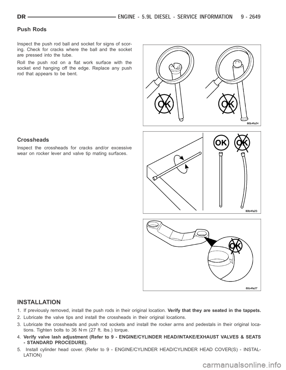
Push Rods
Inspect the push rod ball and socket for signs of scor-
ing. Check for cracks where the ball and the socket
are pressed into the tube.
Roll the push rod on a flat work surface with the
socket end hanging off the edge. Replace any push
rod that appears to be bent.
Crossheads
Inspect the crossheads for cracks and/or excessive
wear on rocker lever and valve tip mating surfaces.
INSTALLATION
1. If previously removed, install the push rods in their original location.Verify that they are seated in the tappets.
2. Lubricate the valve tips and install the crossheads in their original locations.
3. Lubricate the crossheads and push rod sockets and install the rocker arms and pedestals in their original loca-
tions. Tighten bolts to 36 Nꞏm (27 ft. lbs.) torque.
4.Verify valve lash adjustment (Refer to 9 - ENGINE/CYLINDER HEAD/INTAKE/EXHAUST VALVES & SEATS
- STANDARD PROCEDURE).
5. Install cylinder head cover. (Refer to 9 - ENGINE/CYLINDER HEAD/CYLINDER HEAD COVER(S) - INSTAL-
LATION)
Page 1959 of 5267

6. Connect battery negative cables.
Page 1960 of 5267
ENGINE BLOCK
STANDARD PROCEDURE
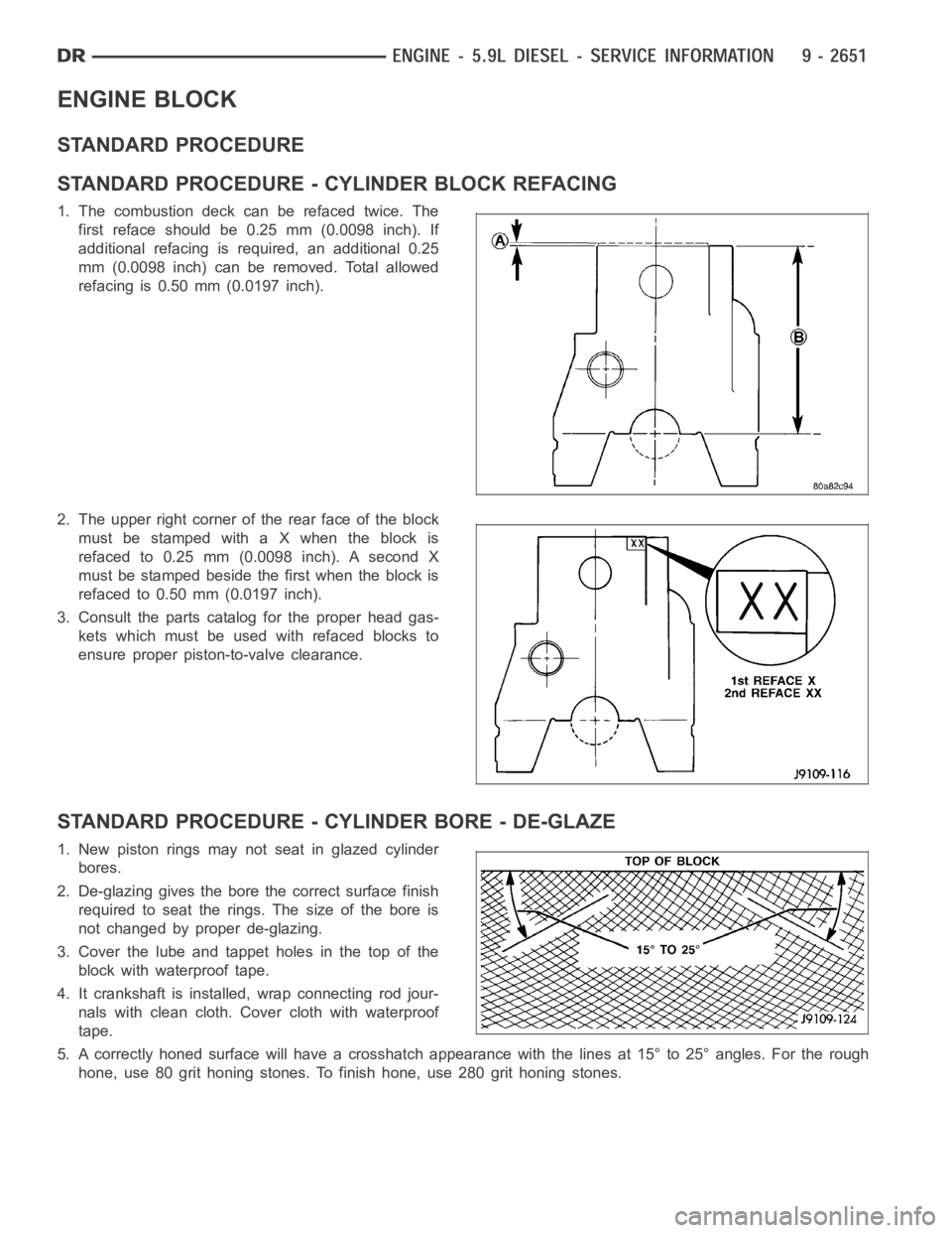
STANDARD PROCEDURE - CYLINDER BLOCK REFACING
1. The combustion deck can be refaced twice. The
first reface should be 0.25 mm (0.0098 inch). If
additional refacing is required, an additional 0.25
mm (0.0098 inch) can be removed. Total allowed
refacing is 0.50 mm (0.0197 inch).
2. The upper right corner of the rear face of the block
must be stamped with a X when the block is
refaced to 0.25 mm (0.0098 inch). A second X
must be stamped beside the first when the block is
refacedto0.50mm(0.0197inch).
3. Consult the parts catalog for the proper head gas-
kets which must be used with refaced blocks to
ensure proper piston-to-valve clearance.
STANDARD PROCEDURE - CYLINDER BORE - DE-GLAZE
1. New piston rings may not seat in glazed cylinder
bores.
2. De-glazing gives the bore the correct surface finish
required to seat the rings. The size of the bore is
not changed by proper de-glazing.
3. Cover the lube and tappet holes in the top of the
block with waterproof tape.
4. It crankshaft is installed, wrap connecting rod jour-
nals with clean cloth. Cover cloth with waterproof
tape.
5. A correctly honed surface will have a crosshatch appearance with the lines at 15° to 25° angles. For the rough
hone, use 80 grit honing stones. To finish hone, use 280 grit honing stones.