air conditioning DODGE RAM SRT-10 2006 Service User Guide
[x] Cancel search | Manufacturer: DODGE, Model Year: 2006, Model line: RAM SRT-10, Model: DODGE RAM SRT-10 2006Pages: 5267, PDF Size: 68.7 MB
Page 1679 of 5267
INSTALLATION
INSTALLATION - RIGHT SIDE
CAUTION: Do not use harsh cleaners to clean the
cylinder head covers. Severe damage to covers
may occur.
1. Clean cylinder head cover and both sealing sur-
faces. Inspect and replace gasket as necessary.
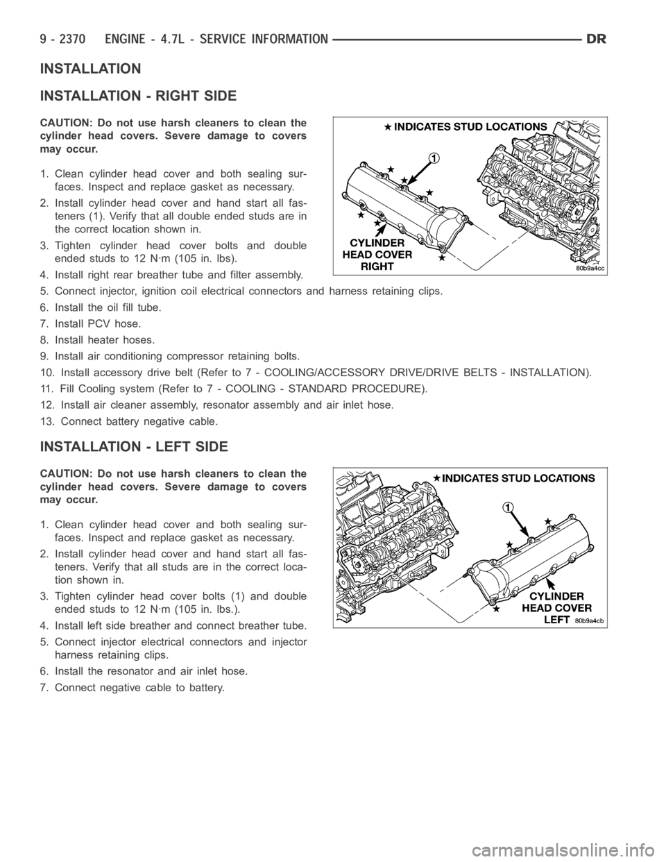
2. Install cylinder head cover and hand start all fas-
teners (1). Verify that all double ended studs are in
the correct location shown in.
3. Tighten cylinder head cover bolts and double
ended studs to 12 Nꞏm (105 in. lbs).
4. Install right rear breather tube and filter assembly.
5. Connect injector, ignition coil electrical connectors and harness retaining clips.
6. Install the oil fill tube.
7. Install PCV hose.
8. Install heater hoses.
9. Install air conditioning compressor retaining bolts.
10. Install accessory drive belt (Refer to 7 - COOLING/ACCESSORY DRIVE/DRIVE BELTS - INSTALLATION).
11. Fill Cooling system (Refer to 7 - COOLING - STANDARD PROCEDURE).
12. Install air cleaner assembly, resonator assembly and air inlet hose.
13. Connect battery negative cable.
INSTALLATION - LEFT SIDE
CAUTION: Do not use harsh cleaners to clean the
cylinder head covers. Severe damage to covers
may occur.
1. Clean cylinder head cover and both sealing sur-
faces. Inspect and replace gasket as necessary.
2. Install cylinder head cover and hand start all fas-
teners. Verify that all studs are in the correct loca-
tion shown in.
3. Tighten cylinder head cover bolts (1) and double
ended studs to 12 Nꞏm (105 in. lbs.).
4. Install left side breather and connect breather tube.
5. Connect injector electrical connectors and injector
harness retaining clips.
6. Install the resonator and air inlet hose.
7. Connect negative cable to battery.
Page 1732 of 5267
MANIFOLD - INTAKE
DESCRIPTION
The intake manifold is made of a composite material and features long runners which maximizes low end torque.
The intake manifold uses single plane sealing which consist of eight individual press in place port gaskets to prevent
leaks. Eight studs and two bolts are used to fasten the intake to the head.
DIAGNOSIS AND TESTING - INTAKE MANIFOLD LEAKAGE
An intake manifold air leak is characterized by lower than normal manifoldvacuum. Also, one or more cylinders may
not be functioning.
WARNING: USE EXTREME CAUTION WHEN THE ENGINE IS OPERATING. DO NOT STAND IN ADIRECT LINE
WITH THE FAN. DO NOT PUT YOUR HANDS NEAR THE PULLEYS, BELTS OR THE FAN. DO NOT WEAR
LOOSE CLOTHING.
1. Start the engine.
2. Spray a small stream of water at the suspected leak area.
3. If a change in RPM is observed the area of the suspected leak has been found.
4. Repair as required.
REMOVAL
1. Disconnect negative cable from battery.
2. Remove resonator assembly and air inlet hose.
3. Disconnect throttle and speed control cables.
4. Disconnect electrical connectors for the following components:
Manifold Absolute Pressure (MAP) Sensor
Intake Air Temperature (IAT) Sensor
Throttle Position (TPS) Sensor
Coolant Temperature (CTS) Sensor
Idle Air Control (IAC) Motor
5. Disconnect brake booster hose and positive crankcase ventilation (PCV)hose.
6. Disconnect generator electrical connections.
7. Disconnect air conditioning compressor electrical connections.
8. Disconnect left and right radio suppressor straps.
9. Disconnect and remove ignition coil towers (Refer to 8 - ELECTRICAL/IGNITION CONTROL/IGNITION COIL -
REMOVAL).
10. Remove top oil dipstick tube retaining bolt and ground strap.
11. Bleed fuel system (Refer to 14 - FUEL SYSTEM/FUEL DELIVERY - STANDARD PROCEDURE).
12. Remove fuel rail (Refer to 14 - FUEL SYSTEM/FUEL DELIVERY/FUEL RAIL - REMOVAL).
13. Remove throttle body assembly and mounting bracket.
14. Drain cooling system below coolant temperature level (Refer to 7 - COOLING - STANDARD PROCEDURE).
Page 1735 of 5267
MANIFOLD - EXHAUST
DESCRIPTION
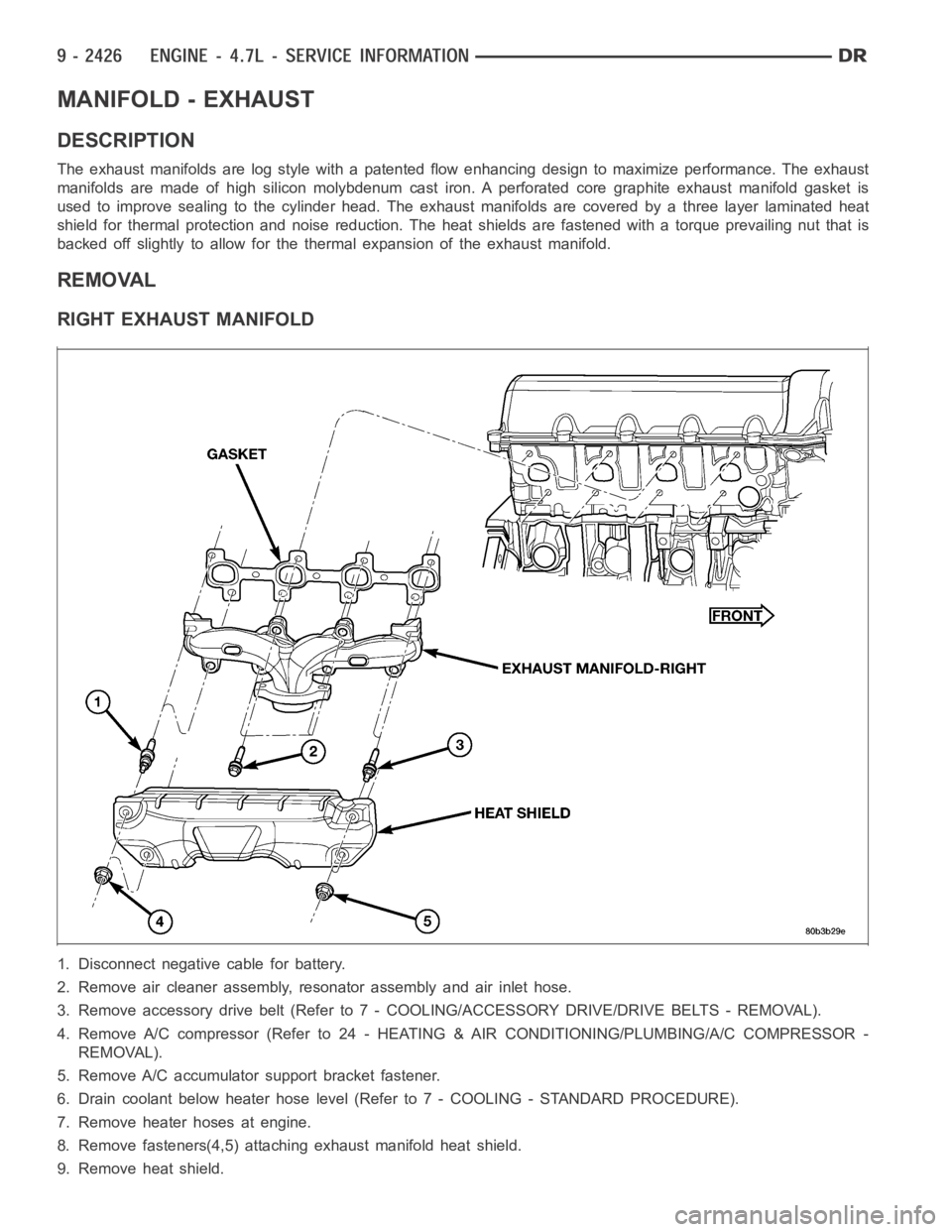
The exhaust manifolds are log style with a patented flow enhancing design to maximize performance. The exhaust
manifolds are made of high silicon molybdenum cast iron. A perforated coregraphite exhaust manifold gasket is
used to improve sealing to the cylinder head. The exhaust manifolds are covered by a three layer laminated heat
shield for thermal protection and noise reduction. The heat shields are fastened with a torque prevailing nut that is
backed off slightly to allow for the thermal expansion of the exhaust manifold.
REMOVAL
RIGHT EXHAUST MANIFOLD
1. Disconnect negative cable for battery.
2. Remove air cleaner assembly, resonator assembly and air inlet hose.
3. Remove accessory drive belt (Refer to 7 - COOLING/ACCESSORY DRIVE/DRIVE BELTS - REMOVAL).
4. Remove A/C compressor (Refer to 24 -HEATING & AIR CONDITIONING/PLUMBING/A/C COMPRESSOR -
REMOVAL).
5. Remove A/C accumulator support bracket fastener.
6. Drain coolant below heater hose level (Refer to 7 - COOLING - STANDARD PROCEDURE).
7. Remove heater hoses at engine.
8. Remove fasteners(4,5) attaching exhaust manifold heat shield.
9. Remove heat shield.
Page 1774 of 5267
17. Install the intake manifold.
18. Using a new gasket, install throttle body (Refer to
14 - FUEL SYSTEM/FUEL INJECTION/THROT-
TLE BODY - INSTALLATION).
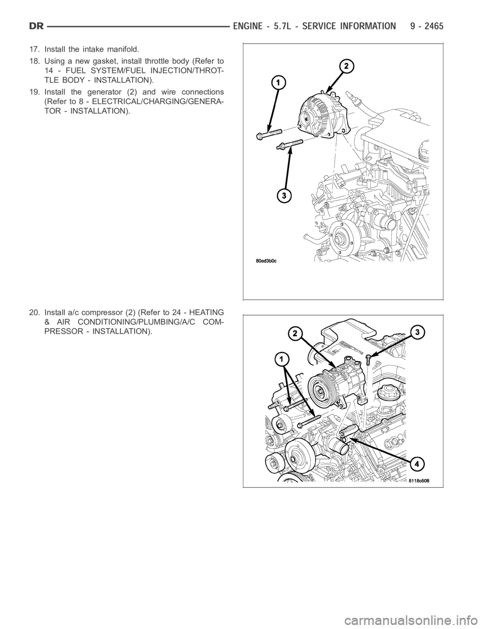
19. Install the generator (2) and wire connections
(Refer to 8 - ELECTRICAL/CHARGING/GENERA-
TOR - INSTALLATION).
20. Install a/c compressor (2) (Refer to 24 - HEATING
& AIR CONDITIONING/PLUMBING/A/C COM-
PRESSOR - INSTALLATION).
Page 1887 of 5267
MANIFOLD - INTAKE
DESCRIPTION
The intake manifold is made of a composite material and features long runners which maximizes low end torque.
The intake manifold uses single plane sealing which consist of eight individual press in place port gaskets to prevent
leaks.
DIAGNOSIS AND TESTING - INTAKE MANIFOLD LEAKAGE
An intake manifold air leak is characterized by lower than normal manifoldvacuum. Also, one or more cylinders may
not be functioning.
WARNING: USE EXTREME CAUTION WHEN THE ENGINE IS OPERATING. DO NOT STAND IN ADIRECT LINE
WITH THE FAN. DO NOT PUT YOUR HANDS NEAR THE PULLEYS, BELTS OR THE FAN. DO NOT WEAR
LOOSE CLOTHING.
1. Start the engine.
2. Spray a small stream of water at the suspected leak area.
3. If a change in RPM is observed the area of the suspected leak has been found.
4. Repair as required.
REMOVAL
1. Disconnect negative cable from battery.
2. Remove resonator assembly and air inlet hose.
3. Disconnect electrical connectors for the following components:
Manifold Absolute Pressure (MAP) Sensor
Intake Air Temperature (IAT) Sensor
Throttle Position (TPS) Sensor
Coolant Temperature (CTS) Sensor
4. Disconnect brake booster hose and positive crankcase ventilation (PCV)hose.
5. Remove generator and set aside.
NOTE: It is not necessary to remove lines or remove freon from A/C compressor.
6. Remove air conditioning compressor and set aside..
7. Bleed fuel system (Refer to 14 - FUEL SYSTEM/FUEL DELIVERY - STANDARD PROCEDURE).
8. Remove intake manifold retaining fasteners in a crisscross pattern starting from the outside bolts and ending at
themiddlebolts.
9. Remove intake manifold and IAFM as an assembly.
CLEANING
NOTE: There is NO approved repair procedure for the intake manifold. If severe damage is found during
inspection, the intake manifold must be replaced.
Before installing the intake manifoldthoroughly clean the mating surfaces. Use a suitable cleaning solvent, then air
dry.
Page 1914 of 5267
3. Place a shop towel around the fuel injectors to catch any fluid that may possibly be under pressure in the cyl-
inder head. Remove the fuel injectors (Refer to 14 - FUEL SYSTEM/FUEL INJECTION/FUEL INJECTOR -
REMOVAL).
4. With all injectors removed, rotatethe crankshaft using the crankshaftbarring tool (PN 7471–B).
5. Identify the fluid in the cylinders (coolant, fuel, oil, etc.).
6. Be sure all fluid has been removed from the cylinders.
7. Repair engine or components as necessary to prevent this problem from occurring again.
8. Squirt a small amount of engine oil into the cylinders to lubricate the walls. This will prevent damage on restart.
9. Install fuel injectors (Refer to 14 - FUEL SYSTEM/FUEL INJECTION/FUEL INJECTOR - INSTALLATION).
10. Drain engine oil. Remove and discard the oil filter (Refer to 9 - ENGINE/LUBRICATION/OIL FILTER -
REMOVAL).
11. Installthedrainplug.Tightentheplugto50Nꞏm(37ft.lbs.)torque.
12. Install a new oil filter (Refer to 9 - ENGINE/LUBRICATION/OIL FILTER - INSTALLATION).
13. Fill engine crankcase with the specified amount and grade of oil (Referto LUBRICATION & MAINTENANCE/
FLUID TYPES - SPECIFICATIONS).
14. Connect the negative cable(s) to the battery.
15. Start the engine and check for any leaks.
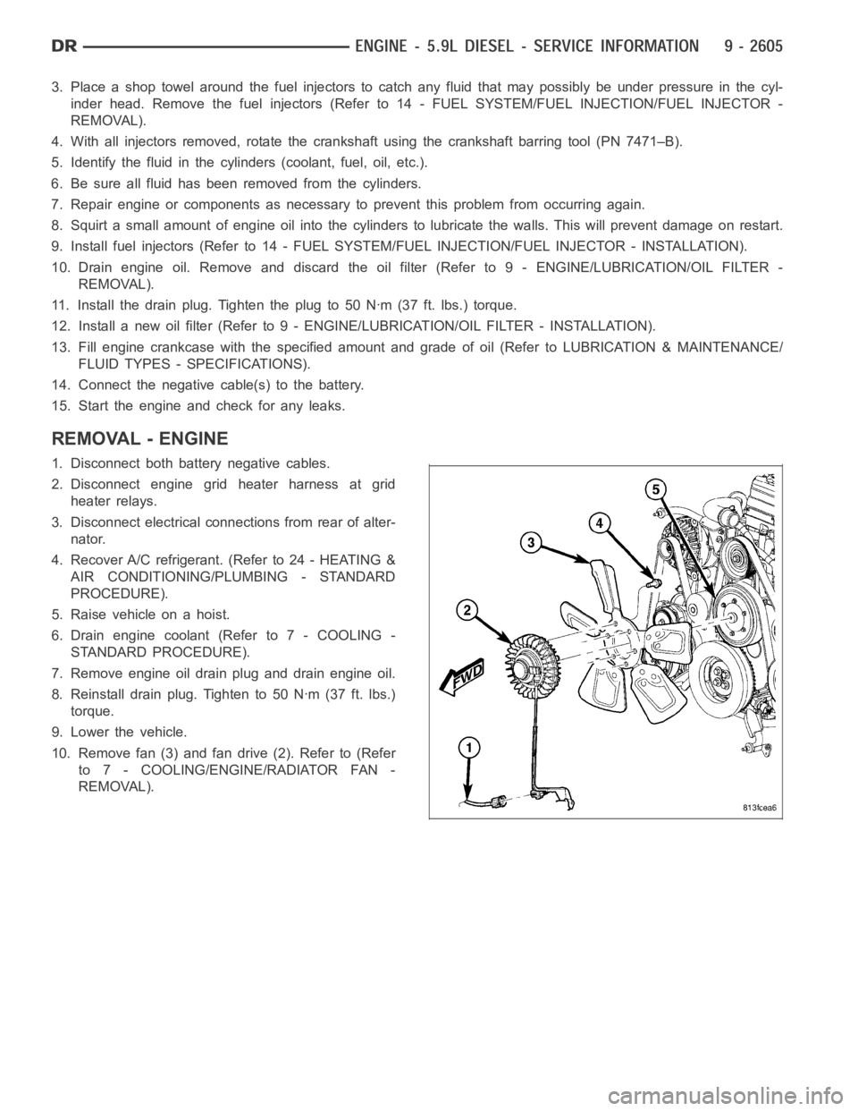
REMOVAL - ENGINE
1. Disconnect both battery negative cables.
2. Disconnect engine grid heater harness at grid
heater relays.
3. Disconnect electrical connections from rear of alter-
nator.
4. Recover A/C refrigerant. (Refer to 24 - HEATING &
AIR CONDITIONING/PLUMBING - STANDARD
PROCEDURE).
5. Raise vehicle on a hoist.
6. Drain engine coolant (Refer to 7 - COOLING -
STANDARD PROCEDURE).
7. Remove engine oil drain plug and drain engine oil.
8. Reinstall drain plug. Tighten to 50 Nꞏm (37 ft. lbs.)
torque.
9. Lower the vehicle.
10. Remove fan (3) and fan drive (2). Refer to (Refer
to 7 - COOLING/ENGINE/RADIATOR FAN -
REMOVAL).
Page 1966 of 5267
CAMSHAFT & BEARINGS (IN BLOCK)
REMOVAL
CAMSHAFT BEARINGS
NOTE: Measure the diameter of each bore. If the camshaft bore for the cam bushing is worn beyond the
limit, install a new service bushing. Inspect the rest of the camshaft bores for damage or excessive wear.If
the bores without a bushing are worn beyond the limit, the engine must be removed for machining and
installation of service bushings. If badly worn, replace the cylinder block.
1. Remove the camshaft (Refer to 9 - ENGINE/ENGINE BLOCK/CAMSHAFT & BEARINGS (IN BLOCK) -
REMOVAL).
2. Remove the bushing from the No.1 bore.
3. Mark the cylinder block so you can align the oil hole in the cylinder blockwith the oil hole in the bushing.
CAMSHAFT
1. Disconnect both battery negative cables.
2. Recover A/C refrigerant (if A/C equipped) (Refer to 24 - HEATING & AIR CONDITIONING/PLUMBING - STAN-
DARD PROCEDURE).
3. Raise vehicle on hoist.
4. Drain engine coolant into container suitable for re-use (Refer to 7 - COOLING - STANDARD PROCEDURE).
5. Lower vehicle.
6. Remove radiator upper hose.
7. Remove viscous fan/drive/shroud assembly (Refer to 7 - COOLING/ENGINE/RADIATOR FAN - REMOVAL).
8. Disconnect the coolant recovery bottle hose from the radiator filler neck.
9. Disconnect lower radiator hose from radiator outlet.
10.Automatic Transmission models:Disconnect transmission oil cooler lines from front of radiator using Special
Tool 6931 (unless equipped with finger-release disconnect).
11. Remove radiator mounting screws and lift radiator out of engine compartment.
12. Remove upper radiator support panel.
13. If A/C equipped, disconnect A/C condenser refrigerant lines.
14. Disconnect charge air cooler piping from the cooler inlet and outlet.
15. Remove the two charge air cooler mounting bolts.
16. Remove charge air cooler (and A/C condenser if equipped) from vehicle.
17. Remove accessory drive belt (Refer to 7 - COOLING/ACCESSORY DRIVE/DRIVE BELTS - REMOVAL).
18. Remove accessory drive belt tensioner.
19. Remove the fan support/hub assembly.
20. Remove crankshaft damper and speed indicator ring (Refer to 9 - ENGINE/ENGINE BLOCK/VIBRATION
DAMPER - REMOVAL).
21. Remove the gear cover-to-housing bolts and gently pry the cover away from the housing, taking care not to mar
the sealing surfaces. Remove dust seal with cover.
22. Using Special Tool 7471–B Crankshaft Barring Tool, rotate the crankshaft to align the timing marks on the
crankshaft and the camshaft gears.
23. Remove the cylinder head cover (Refer to 9 - ENGINE/CYLINDER HEAD/CYLINDER HEAD COVER(S) -
REMOVAL).
Page 1971 of 5267
12. Install gear housing cover (Refer to 9 - ENGINE/VALVE TIMING/GEAR HOUSING COVER - INSTALLATION).
Install front crankshaft dust seal.
13. Install the crankshaft damper with the speed indicator ring (Refer to 9- ENGINE/ENGINE BLOCK/VIBRATION
DAMPER - INSTALLATION).
14. Install the fan support/hub assembly Refer to (Refer to 7 - COOLING/ENGINE/RADIATOR FAN - INSTALLA-
TION).
15. Install the power steering pump.
16. Install accessory drive belt tensioner. Torque bolt to 43 Nꞏm (32 ft. lbs.).
17. Install the accessory drive belt (Refer to 7 - COOLING/ACCESSORY DRIVE/DRIVE BELTS - INSTALLATION).
18. Install the charge air cooler (with a/c condenser and auxiliary transmission oil cooler, if equipped) and tighten
the mounting bolts to 2 Nꞏm (17 in. lbs.) torque.
19. Connect charge air cooler inlet and outlet pipes. Tighten clamps to 11 Nꞏm (95 in. lbs.) torque.
20. Install the radiator upper support panel.
21. Close radiator petcock and lower the radiator into the engine compartment. Tighten the mounting bolts to 11
Nꞏm (95 in. lbs.) torque.
22. Raise vehicle on hoist.
23. Connect radiator lower hose and install clamp.
24. Connect transmission auxiliary oil cooler lines (if equipped).
25. Lower vehicle.
26. Install the fandrive/shroud assembly. (Refer to 7 - COOLING/ENGINE/RADIATOR FAN - INSTALLATION)
27. Install the coolant recovery and windshield washer fluid reservoirs to the fan shroud.
28. Connect the coolant recovery hose to the radiator filler neck.
29. Add engine coolant (Refer to 7 - COOLING - STANDARD PROCEDURE).
30. Charge A/C system with refrigerant (if A/C equipped) (Refer to 24 - HEATING & AIR CONDITIONING/PLUMB-
ING - STANDARD PROCEDURE).
31. Connect the battery negative cables.
32. Start engine and check for engine oil and coolant leaks.
Page 2033 of 5267
5. Identify the fluid in the cylinder(s) (i.e., coolant, fuel, oil or other).
6. Make sure all fluid has been removed from the cylinders. Inspect engine for damage (i.e., connecting rods, pis-
tons, valves, etc.)
7. Repair engine or components as necessary to prevent this problem from re-occurring.
CAUTION: Squirt approximately one teaspoon of oil into the cylinders, rotateenginetolubricatethecylin-
der walls to prevent damage on restart.
8. Install new spark plugs.
9. Drain engine oil and remove oil filter.
10. Fill engine with specified amount of approved oil and install new oil filter.
11. Connect negative battery cable.
12. Start engine and check for any leaks.
REMOVAL - ENGINE ASSEMBLY
1. Perform fuel pressure release procedure (Refer to
14 - FUEL SYSTEM/FUEL DELIVERY - STAN-
DARD PROCEDURE).
2. Disconnect negative battery cable.
3. Disconnect throttle body air inlet duct, remove air
cleaner cover (Refer to 9 - ENGINE/AIR INTAKE
SYSTEM/AIR CLEANER ELEMENT - REMOVAL).
4. Raise and support the vehicle.
5. Remove the lower engine shield.
6. Drain cooling system (Refer to 7 - COOLING/EN-
GINE - STANDARD PROCEDURE - DRAINING
COOLING SYSTEM).
7. Paint mark and remove the driveshaft (Refer to 3 -
DIFFERENTIAL & DRIVELINE/PROPELLER
SHAFT/PROPELLER SHAFT - REMOVAL).
8.Removethetransmission(Referto21-TRANS-
MISSION/TRANSAXLE/MANUAL - REMOVAL).
9. Remove the starter (Refer to 8 - ELECTRICAL/
STARTING/STARTER MOTOR - REMOVAL).
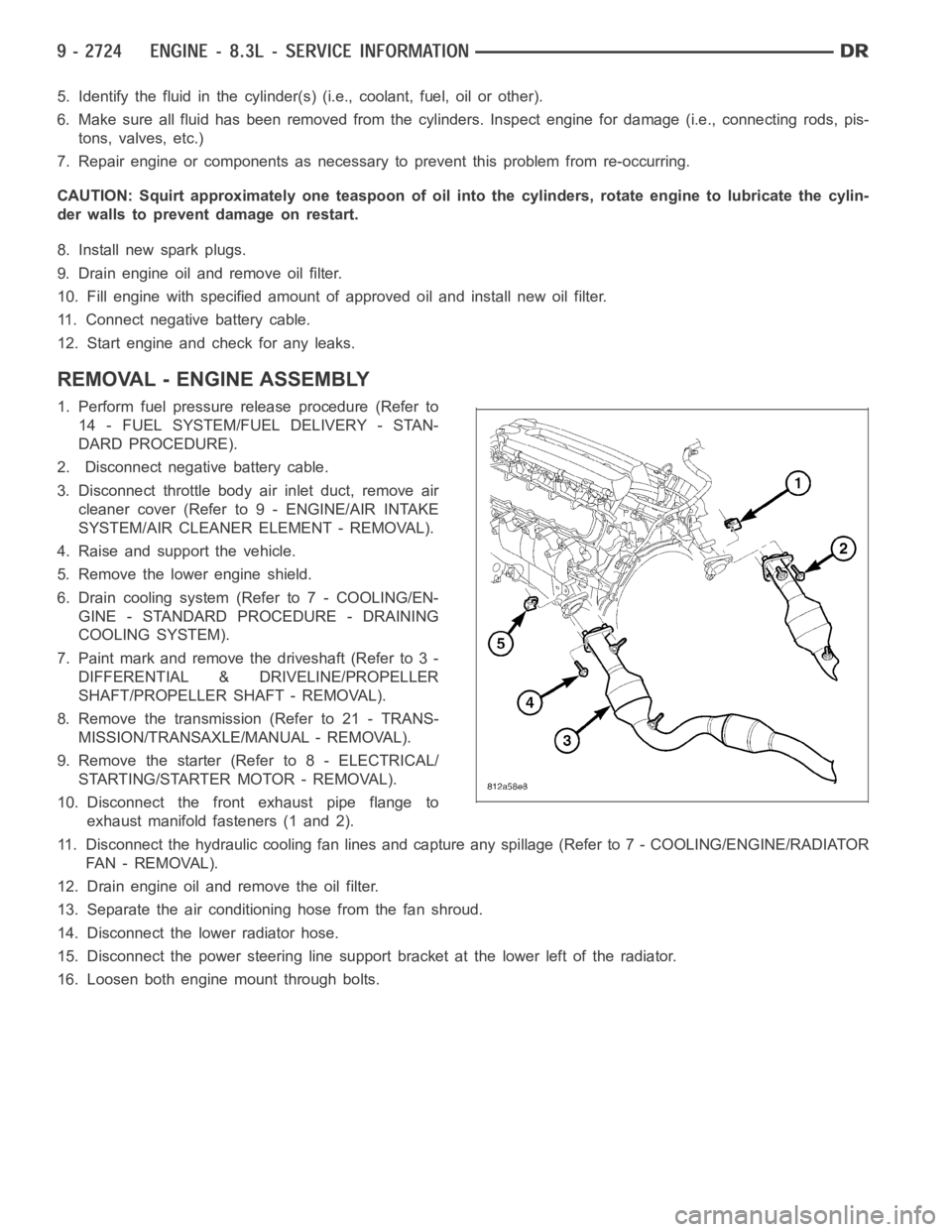
10. Disconnect the front exhaust pipe flange to
exhaust manifold fasteners (1 and 2).
11. Disconnect the hydraulic cooling fan lines and capture any spillage (Refer to 7 - COOLING/ENGINE/RADIATOR
FA N - R E M O VA L ) .
12. Drain engine oil and remove the oil filter.
13. Separate the air conditioning hose from the fan shroud.
14. Disconnect the lower radiator hose.
15. Disconnect the power steering line support bracket at the lower left ofthe radiator.
16. Loosen both engine mount through bolts.
Page 2034 of 5267
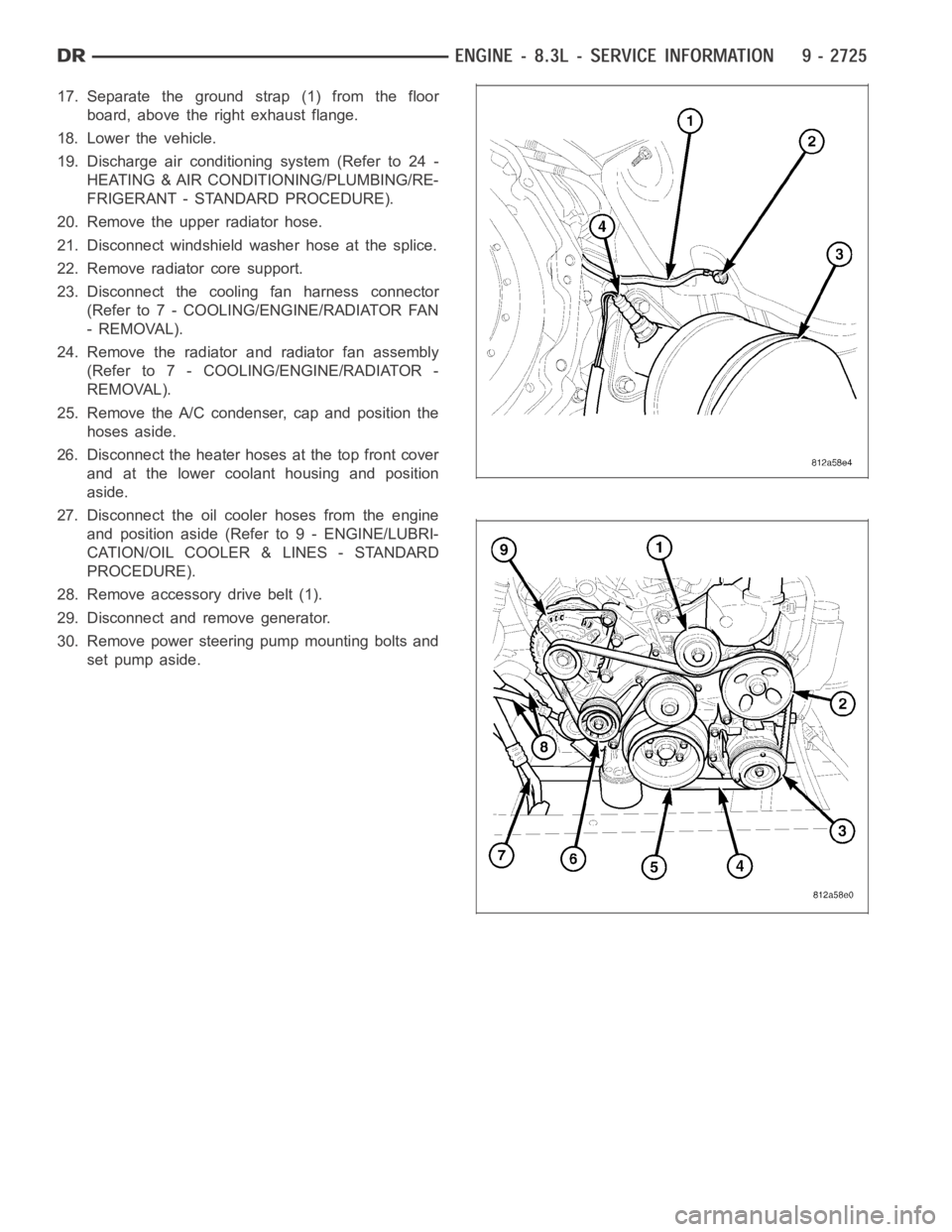
17. Separate the ground strap (1) from the floor
board, above the right exhaust flange.
18. Lower the vehicle.
19. Discharge air conditioning system (Refer to 24 -
HEATING & AIR CONDITIONING/PLUMBING/RE-
FRIGERANT - STANDARD PROCEDURE).
20. Remove the upper radiator hose.
21. Disconnect windshield washer hose at the splice.
22. Remove radiator core support.
23. Disconnect the cooling fan harness connector
(Refer to 7 - COOLING/ENGINE/RADIATOR FAN
- REMOVAL).
24. Remove the radiator and radiator fan assembly
(Refer to 7 - COOLING/ENGINE/RADIATOR -
REMOVAL).
25. Remove the A/C condenser, cap and position the
hoses aside.
26. Disconnect the heater hoses at the top front cover
and at the lower coolant housing and position
aside.
27. Disconnect the oil cooler hoses from the engine
and position aside (Refer to 9 - ENGINE/LUBRI-
CATION/OIL COOLER & LINES - STANDARD
PROCEDURE).
28. Remove accessory drive belt (1).
29. Disconnect and remove generator.
30. Remove power steering pump mounting bolts and
set pump aside.