check transmission fluid DODGE RAM SRT-10 2006 Service Owner's Manual
[x] Cancel search | Manufacturer: DODGE, Model Year: 2006, Model line: RAM SRT-10, Model: DODGE RAM SRT-10 2006Pages: 5267, PDF Size: 68.7 MB
Page 2891 of 5267
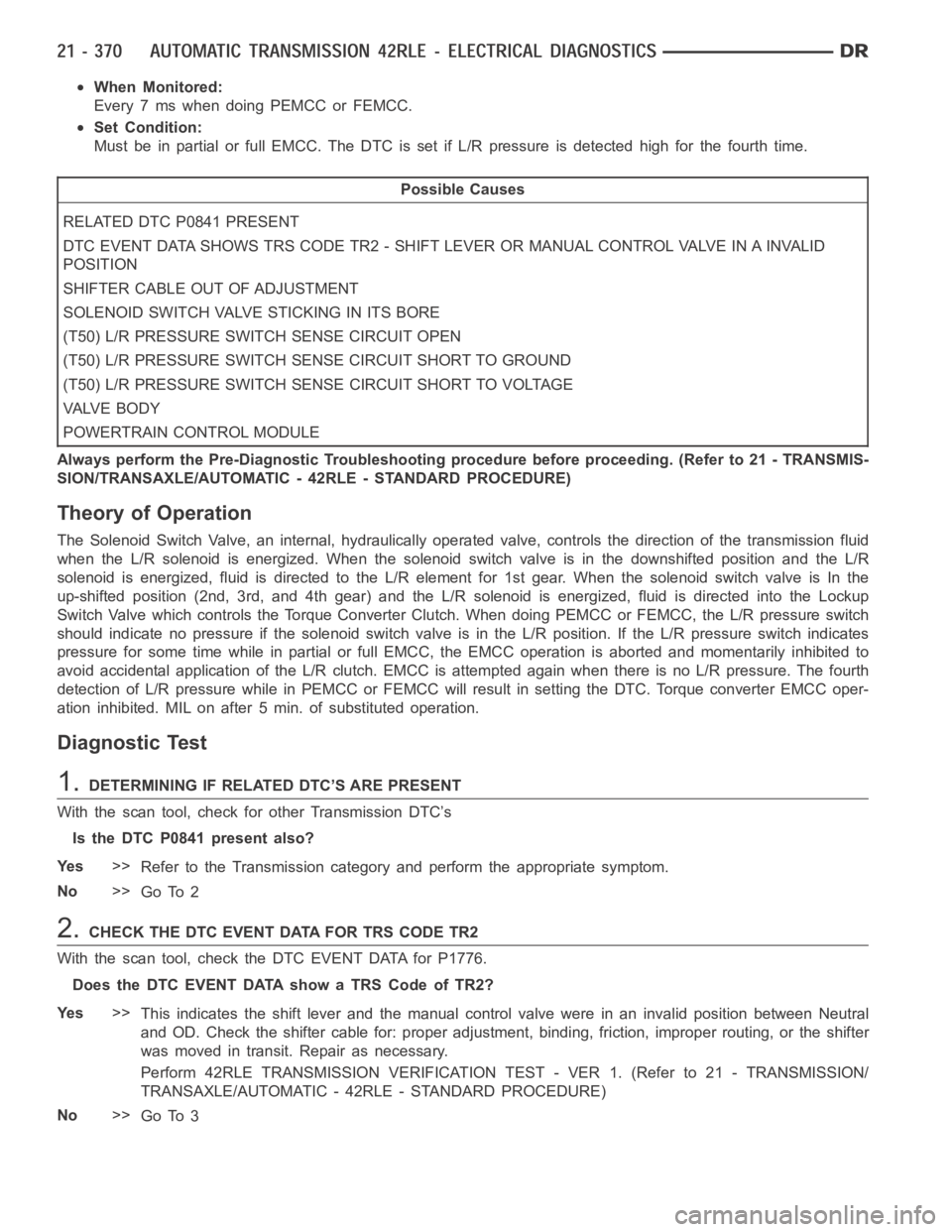
When Monitored:
Every 7 ms when doing PEMCC or FEMCC.
Set Condition:
Must be in partial or full EMCC. The DTC is set if L/R pressure is detected high for the fourth time.
Possible Causes
RELATED DTC P0841 PRESENT
DTC EVENT DATA SHOWS TRS CODE TR2 - SHIFT LEVER OR MANUAL CONTROL VALVE IN A INVA L I D
POSITION
SHIFTER CABLE OUT OF ADJUSTMENT
SOLENOID SWITCH VALVE STICKING IN ITS BORE
(T50) L/R PRESSURE SWITCH SENSE CIRCUIT OPEN
(T50) L/R PRESSURE SWITCH SENSE CIRCUIT SHORT TO GROUND
(T50) L/R PRESSURE SWITCH SENSE CIRCUIT SHORT TO VOLTAGE
VA LV E B O D Y
POWERTRAIN CONTROL MODULE
Always perform the Pre-Diagnostic Troubleshooting procedure before proceeding. (Refer to 21 - TRANSMIS-
SION/TRANSAXLE/AUTOMATIC - 42RLE - STANDARD PROCEDURE)
Theory of Operation
The Solenoid Switch Valve, an internal, hydraulically operated valve, controls the direction of the transmission fluid
when the L/R solenoid is energized. When the solenoid switch valve is in thedownshifted position and the L/R
solenoid is energized, fluid is directed to the L/R element for 1st gear. When the solenoid switch valve is In the
up-shifted position (2nd, 3rd, and 4th gear) and the L/R solenoid is energized, fluid is directed into the Lockup
Switch Valve which controls the Torque Converter Clutch. When doing PEMCCor FEMCC, the L/R pressure switch
should indicate no pressure if the solenoid switch valve is in the L/R position. If the L/R pressure switch indicates
pressure for some time while in partial or full EMCC, the EMCC operation is aborted and momentarily inhibited to
avoid accidental application of the L/R clutch. EMCC is attempted again when there is no L/R pressure. The fourth
detection of L/R pressure while in PEMCC or FEMCC will result in setting theDTC. Torque converter EMCC oper-
ation inhibited. MIL on after 5 min. of substituted operation.
Diagnostic Test
1.DETERMINING IF RELATED DTC’S ARE PRESENT
With the scan tool, check for other Transmission DTC’s
Is the DTC P0841 present also?
Ye s>>
Refer to the Transmission category and perform the appropriate symptom.
No>>
Go To 2
2.CHECK THE DTC EVENT DATA FOR TRS CODE TR2
With the scan tool, check the DTC EVENT DATA for P1776.
Does the DTC EVENT DATA show a TRS Code of TR2?
Ye s>>
This indicates the shift lever and the manual control valve were in an invalid position between Neutral
and OD. Check the shifter cable for: proper adjustment, binding, friction, improper routing, or the shifter
was moved in transit. Repair as necessary.
Perform 42RLE TRANSMISSION VERIFICATION TEST - VER 1. (Refer to 21 - TRANSMISSION/
TRANSAXLE/AUTOMATIC - 42RLE - STANDARD PROCEDURE)
No>>
Go To 3
Page 2899 of 5267
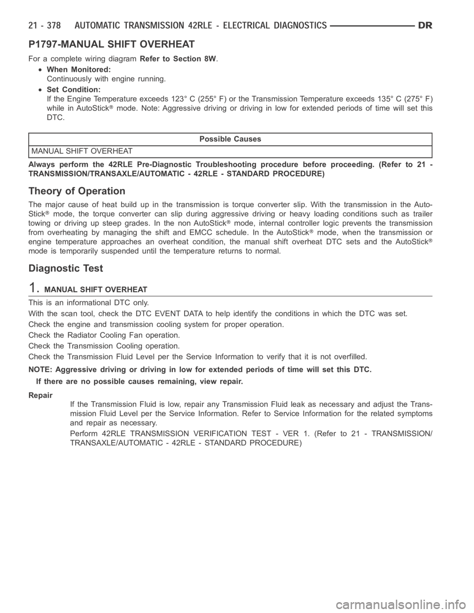
P1797-MANUAL SHIFT OVERHEAT
For a complete wiring diagramRefer to Section 8W.
When Monitored:
Continuously with engine running.
Set Condition:
If the Engine Temperature exceeds 123° C (255° F) or the Transmission Temperature exceeds 135° C (275° F)
while in AutoStick
mode. Note: Aggressive driving or driving in low for extended periods of time will set this
DTC.
Possible Causes
MANUAL SHIFT OVERHEAT
Always perform the 42RLE Pre-Diagnostic Troubleshooting procedure before proceeding. (Refer to 21 -
TRANSMISSION/TRANSAXLE/AUTOMATIC - 42RLE - STANDARD PROCEDURE)
Theory of Operation
The major cause of heat build up in the transmission is torque converter slip.WiththetransmissionintheAuto-
Stick
mode, the torque converter can slip during aggressive driving or heavy loading conditions such as trailer
towing or driving up steep grades. In the non AutoStick
mode, internal controller logic prevents the transmission
from overheating by managing the shift and EMCC schedule. In the AutoStick
mode, when the transmission or
engine temperature approaches an overheat condition, the manual shift overheat DTC sets and the AutoStick
mode is temporarily suspended until the temperature returns to normal.
Diagnostic Test
1.MANUAL SHIFT OVERHEAT
This is an informational DTC only.
With the scan tool, check the DTC EVENT DATA to help identify the conditionsin which the DTC was set.
Check the engine and transmission cooling system for proper operation.
Check the Radiator Cooling Fan operation.
Check the Transmission Cooling operation.
Check the Transmission Fluid Level per the Service Information to verify that it is not overfilled.
NOTE: Aggressive driving or driving in low for extended periods of time will set this DTC.
If there are no possible causes remaining, view repair.
Repair
If the Transmission Fluid is low, repair any Transmission Fluid leak as necessary and adjust the Trans-
mission Fluid Level per the Service Information. Refer to Service Information for the related symptoms
and repair as necessary.
Perform 42RLE TRANSMISSION VERIFICATION TEST - VER 1. (Refer to 21 - TRANSMISSION/
TRANSAXLE/AUTOMATIC - 42RLE - STANDARD PROCEDURE)
Page 2908 of 5267
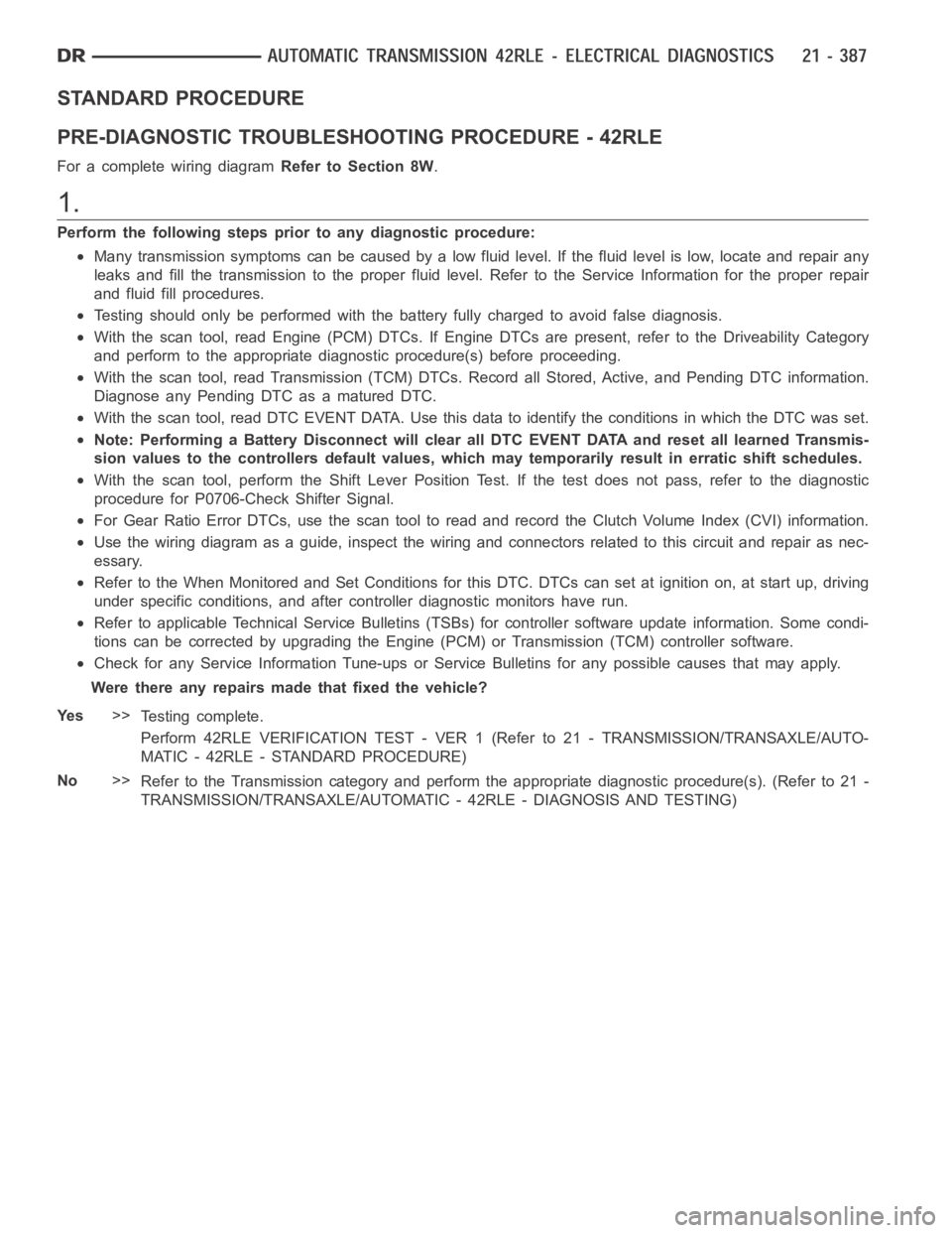
STANDARD PROCEDURE
PRE-DIAGNOSTIC TROUBLESHOOTING PROCEDURE - 42RLE
For a complete wiring diagramRefer to Section 8W.
1.
Perform the following steps prior to any diagnostic procedure:
Many transmission symptoms can be caused by a low fluid level. If the fluid level is low, locate and repair any
leaks and fill the transmission to the proper fluid level. Refer to the Service Information for the proper repair
and fluid fill procedures.
Testing should only be performed with the battery fully charged to avoid false diagnosis.
With the scan tool, read Engine (PCM) DTCs. If Engine DTCs are present, refer to the Driveability Category
and perform to the appropriate diagnostic procedure(s) before proceeding.
With the scan tool, read Transmission (TCM) DTCs. Record all Stored, Active, and Pending DTC information.
Diagnose any Pending DTC as a matured DTC.
With the scan tool, read DTC EVENT DATA.Use this data to identify the conditions in which the DTC was set.
Note: Performing a Battery Disconnect will clear all DTC EVENT DATA and reset all learned Transmis-
sion values to the controllers default values, which may temporarily result in erratic shift schedules.
With the scan tool, perform the Shift Lever Position Test. If the test does not pass, refer to the diagnostic
procedure for P0706-Check Shifter Signal.
For Gear Ratio Error DTCs, use the scan tool to read and record the Clutch Volume Index (CVI) information.
Use the wiring diagram as a guide, inspect the wiring and connectors related to this circuit and repair as nec-
essary.
Refer to the When Monitored and Set Conditions for this DTC. DTCs can set at ignition on, at start up, driving
under specific conditions, and after controller diagnostic monitors haverun.
Refer to applicable Technical Service Bulletins (TSBs) for controller software update information. Some condi-
tions can be corrected by upgrading the Engine (PCM) or Transmission (TCM)controller software.
Check for any Service Information Tune-ups or Service Bulletins for any possible causes that may apply.
Were there any repairs made that fixed the vehicle?
Ye s>>
Testing complete.
Perform 42RLE VERIFICATION TEST - VER1(Referto21-TRANSMISSION/TRANSAXLE/AUTO-
MATIC - 42RLE - STANDARD PROCEDURE)
No>>
Refer to the Transmission category and perform the appropriate diagnostic procedure(s). (Refer to 21 -
TRANSMISSION/TRANSAXLE/AUTOMATIC - 42RLE - DIAGNOSIS AND TESTING)
Page 2909 of 5267
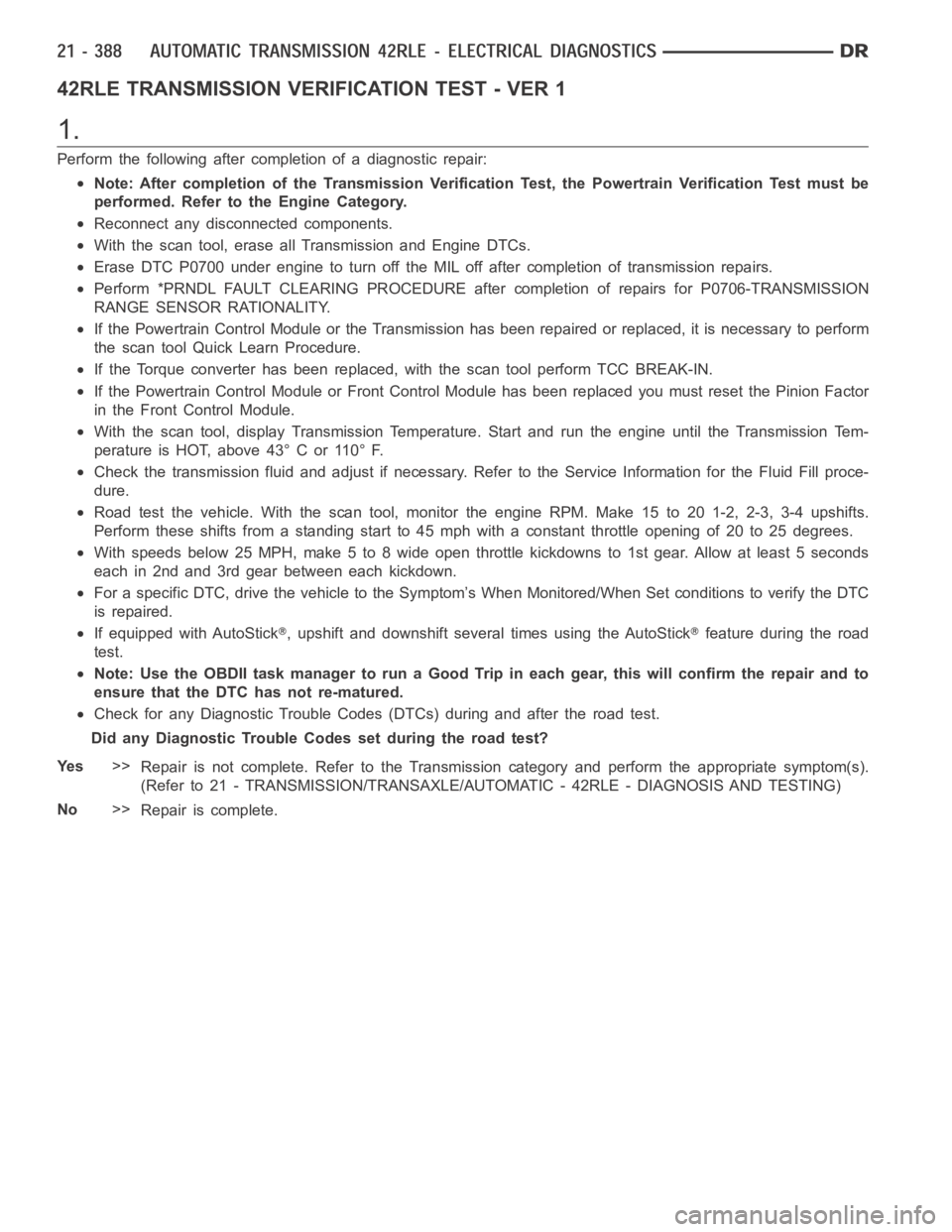
42RLE TRANSMISSION VERIFICATION TEST - VER 1
1.
Perform the following after completion of a diagnostic repair:
Note: After completion of the Transmission Verification Test, the Powertrain Verification Test must be
performed. Refer to the Engine Category.
Reconnect any disconnected components.
With the scan tool, erase all Transmission and Engine DTCs.
Erase DTC P0700 under engine to turn off the MIL off after completion of transmission repairs.
Perform *PRNDL FAULT CLEARING PROCEDURE after completion of repairs for P0706-TRANSMISSION
RANGE SENSOR RATIONALITY.
If the Powertrain Control Module or the Transmission has been repaired or replaced, it is necessary to perform
the scan tool Quick Learn Procedure.
If the Torque converter has been replaced, with the scan tool perform TCC BREAK-IN.
If the Powertrain Control Module or Front Control Module has been replacedyoumustresetthePinionFactor
in the Front Control Module.
With the scan tool, display Transmission Temperature. Start and run the engine until the Transmission Tem-
perature is HOT, above 43° C or 110° F.
Check the transmission fluid and adjust if necessary. Refer to the ServiceInformation for the Fluid Fill proce-
dure.
Road test the vehicle. With the scan tool, monitor the engine RPM. Make 15 to20 1-2, 2-3, 3-4 upshifts.
Perform these shifts from a standing start to 45 mph with a constant throttleopeningof20to25degrees.
With speeds below 25 MPH, make 5 to 8 wide open throttle kickdowns to 1st gear. Allow at least 5 seconds
each in 2nd and 3rd gear between each kickdown.
For a specific DTC, drive the vehicle to the Symptom’s When Monitored/WhenSet conditions to verify the DTC
is repaired.
If equipped with AutoStick, upshift and downshift several times using the AutoStickfeature during the road
test.
Note: Use the OBDII task manager to run a Good Trip in each gear, this will confirm the repair and to
ensure that the DTC has not re-matured.
Check for any Diagnostic Trouble Codes (DTCs) during and after the road test.
Did any Diagnostic Trouble Codes set during the road test?
Ye s>>
Repair is not complete. Refer to the Transmission category and perform theappropriate symptom(s).
(Refer to 21 - TRANSMISSION/TRANSAXLE/AUTOMATIC - 42RLE - DIAGNOSIS AND TESTING)
No>>
Repair is complete.
Page 2910 of 5267
page page
AUTOMATIC TRANSMISSION 42RLE - SERVICE
INFORMATION
DESCRIPTION ............................... 391
OPERATION ................................. 393
DIAGNOSIS AND TESTING
AUTOMATIC TRANSMISSION ............... 398
ROAD TEST ............................... 399
HYDRAULIC PRESSURE TESTS............ 400
CLUTCH AIR PRESSURE TESTS........... 402
FLUID LEAKAGE.......................... 403
STANDARD PROCEDURE - ALUMINUM
THREAD REPAIR .......................... 404
REMOVAL ................................... 404
DISASSEMBLY .............................. 406
ASSEMBLY .................................. 428
INSTALLATION .............................. 451
SCHEMATICS AND DIAGRAMS
42RLE - WITHOUT VARIABLE LINE
PRESSURE............................... 455
42RLE - WITH VARIABLE LINE PRESSURE . . 469
SPECIFICATIONS
42RLE AUTOMATIC TRANSMISSION ........ 479
SPECIAL TOOLS
42RLE AUTOMATIC TRANSMISSION ........ 481
ACCUMULATOR
DESCRIPTION ............................... 485
OPERATION ................................. 486
SEAL-ADAPTER HOUSING
REMOVAL ................................... 487
INSTALLATION .............................. 487
BEARINGS
ADJUSTMENTS
BEARING ADJUSTMENT PROCEDURES.... 488
MECHANISM-BRAKE TRANSMISSION SHIFT
INTERLOCK
DESCRIPTION ............................... 489
OPERATION ................................. 489
DIAGNOSIS AND TESTING - BRAKE
TRANSMISSION SHIFT INTERLOCK ......... 489
ADJUSTMENTS - BRAKE TRANSMISSION
SHIFT INTERLOCK ......................... 489
CLUTCHES-DRIVING
DESCRIPTION ............................... 491
OPERATION ................................. 491
SEAL-EXTENSION HOUSING
REMOVAL ................................... 492
INSTALLATION .............................. 492
FLUID AND FILTER
DIAGNOSIS AND TESTING
CAUSES OF BURNT FLUID ................. 493EFFECTS OF INCORRECT FLUID LEVEL . . . . 493
FLUID CONTAMINATION ................... 493
STANDARD PROCEDURE
FLUID LEVEL CHECK...................... 493
FLUID/FILTER SERVICE .................... 494
TRANSMISSION FILL ...................... 495
CABLE-GEARSHIFT
DIAGNOSIS AND TESTING - GEARSHIFT
CABLE .................................... 496
REMOVAL ................................... 496
INSTALLATION .............................. 497
ADJUSTMENTS - GEARSHIFT CABLE ......... 498
CLUTCHES-HOLDING
DESCRIPTION ............................... 499
OPERATION ................................. 499
ASSEMBLY-INPUT CLUTCH
DISASSEMBLY .............................. 500
ASSEMBLY .................................. 509
SENSOR-INPUT SPEED
DESCRIPTION ............................... 523
OPERATION ................................. 523
REMOVAL ................................... 523
INSTALLATION .............................. 524
SENSOR-VARIABLE LINE PRESSURE
DESCRIPTION ............................... 525
OPERATION ................................. 525
REMOVAL ................................... 525
INSTALLATION .............................. 526
PUMP-OIL
DESCRIPTION ............................... 527
OPERATION ................................. 527
DISASSEMBLY .............................. 527
ASSEMBLY .................................. 529
SENSOR-OUTPUT SPEED
DESCRIPTION ............................... 530
OPERATION ................................. 530
REMOVAL ................................... 530
INSTALLATION .............................. 531
GEARTRAIN-PLANETARY
DESCRIPTION ............................... 532
OPERATION ................................. 532
SEAL-OIL PUMP
REMOVAL ................................... 533
INSTALLATION .............................. 533
SOLENOID-PRESSURE CONTROL
DESCRIPTION ............................... 534
OPERATION ................................. 534
REMOVAL ................................... 534
INSTALLATION .............................. 535
Page 2920 of 5267

Dynamic conditions (acceleration, deceleration, upshift, cornering)
Elements in use when condition occurs (what gear is transmission in duringcondition)
Road and weather conditions
Any other useful diagnostic information.
After noting all conditions, check the easily accessible variables:
Fluid level and condition
Shift cable adjustment
Diagnostic trouble code inspection
Then perform a road test to determine if the problem has been corrected or that more diagnosis is necessary. If the
problem exists after the preliminary tests and corrections are completed, hydraulic pressure checks should be per-
formed.
ROAD TEST
Prior to performing a road test, verify that the fluid level, fluid condition, and linkage adjustment have been
approved.
During the road test, the transmission should be operated in each positionto check for slipping and any variation in
shifting.
If the vehicle operates properly at highway speeds, but has poor acceleration, the converter stator overrunning
clutch may be slipping. If acceleration is normal, but high throttle opening is needed to maintain highway speeds,
the converter stator clutch may have seized. Both of these stator defects require replacement of the torque con-
verter and thorough transmission cleaning.
Slipping clutches can be isolated by comparing the “Elements in Use” chartwith clutch operation encountered on a
road test. This chart identifies which clutches are applied at each position of the selector lever.
A slipping clutch may also set a DTC and can be determined by operating the transmission in all selector positions.
ELEMENTS IN USE AT EACH POSITION OF SELECTOR LEVER
Shift Lever
PositionINPUT CLUTCHES HOLDING CLUTCHES
Underdrive Overdrive Reverse 2/4 Low/Reverse
P-PARKX
R-REVERSE X X
N - NEUTRALX
OD -
OVERDRIVE
First XX
Second X X
Direct X X
Overdrive X X
D - DRIVE*
First XX
Second X X
Direct X X
L-LOW*
First XX
Second X X
Direct X X
* Vehicle upshift and downshift speeds are increased when in these selector positions.
The process of elimination can be used to detect any unit which slips and to confirm proper operation of good units.
Road test analysis can diagnose slipping units, but the cause of the malfunction cannot be determined. Practically
any condition can be caused by leaking hydraulic circuits or sticking valves.
Page 2921 of 5267
HYDRAULIC PRESSURE TESTS
Pressure testing is a very important step in the diag-
nostic procedure. These tests usually reveal the cause
of most transmission problems.
Before performing pressure tests, be certain that fluid
level and condition, and shift cable adjustments have
been checked and approved. Fluid must be at operat-
ing temperature (150 to 200 degrees F.).
Install an engine tachometer, raise vehicle on hoist
which allows the wheels to turn, and position tachom-
eter so it can be read.
Using special adapters L-4559, attach 300 psi
gauge(s) C-3293SP to the port(s) required for test
being conducted.
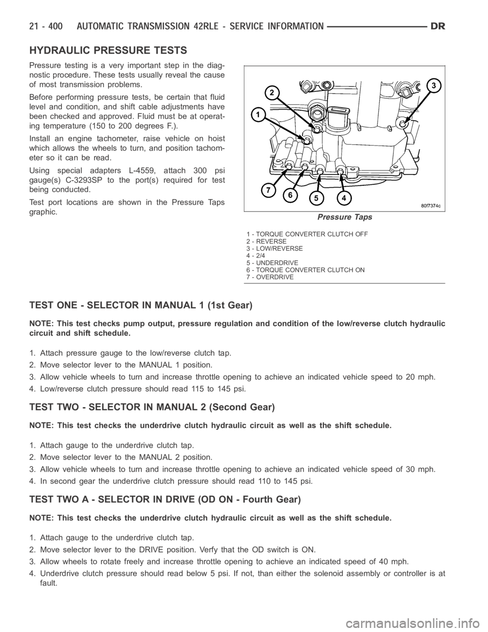
Test port locations are shown in the Pressure Taps
graphic.
TEST ONE - SELECTOR IN MANUAL 1 (1st Gear)
NOTE: This test checks pump output, pressure regulation and condition of the low/reverse clutch hydraulic
circuit and shift schedule.
1. Attach pressure gauge to the low/reverse clutch tap.
2. Move selector lever to the MANUAL 1 position.
3. Allow vehicle wheels to turn and increase throttle opening to achieve anindicatedvehiclespeedto20mph.
4. Low/reverse clutch pressure should read 115 to 145 psi.
TEST TWO - SELECTOR IN MANUAL 2 (Second Gear)
NOTE: This test checks the underdrive clutch hydraulic circuit as well as the shift schedule.
1. Attach gauge to the underdrive clutch tap.
2. Move selector lever to the MANUAL 2 position.
3. Allow vehicle wheels to turn and increase throttle opening to achieve anindicated vehicle speed of 30 mph.
4. In second gear the underdrive clutch pressure should read 110 to 145 psi.
TEST TWO A - SELECTOR IN DRIVE (OD ON - Fourth Gear)
NOTE: This test checks the underdrive clutch hydraulic circuit as well as the shift schedule.
1. Attach gauge to the underdrive clutch tap.
2. Move selector lever to the DRIVE position. Verfy that the OD switch is ON.
3. Allow wheels to rotate freely and increase throttle opening to achieve an indicated speed of 40 mph.
4. Underdrive clutch pressure should read below 5 psi. If not, than either the solenoid assembly or controller is at
fault.
Pressure Taps
1 - TORQUE CONVERTER CLUTCH OFF
2 - REVERSE
3 - LOW/REVERSE
4-2/4
5 - UNDERDRIVE
6 - TORQUE CONVERTER CLUTCH ON
7-OVERDRIVE
Page 2924 of 5267
OVERDRIVE CLUTCH
Apply air pressure to the overdrive clutch apply passage and watch for the push/pull piston to move forward. The
piston should return to its starting position when the air pressure is removed.
REVERSE CLUTCH
Apply air pressure to the reverse clutch apply passage and watch for the push/pull piston to move rearward. The
piston should return to its starting position when the air pressure is removed.
LOW/REVERSE CLUTCH
Apply air pressure to the low/reverse clutch feed hole passage. Look in thearea where the low/reverse piston con-
tacts the first separator plate. Watch carefully for the piston to move forward. The piston should return to its original
position after the air pressure is removed.
UNDERDRIVE CLUTCH
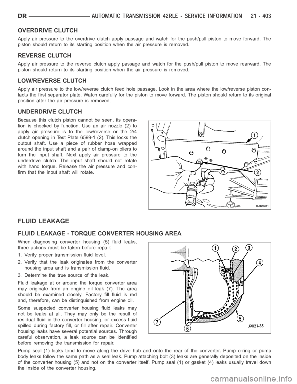
Because this clutch piston cannot be seen, its opera-
tion is checked by function. Use an air nozzle (2) to
apply air pressure is to the low/reverse or the 2/4
clutch opening in Test Plate 6599-1 (2). This locks the
output shaft. Use a piece of rubber hose wrapped
around the input shaft and a pair of clamp-on pliers to
turn the input shaft. Next apply air pressure to the
underdrive clutch. The input shaft should not rotate
with hand torque. Release the air pressure and con-
firm that the input shaft will rotate.
FLUID LEAKAGE
FLUID LEAKAGE - TORQUE CONVERTER HOUSING AREA
When diagnosing converter housing (5) fluid leaks,
three actions must be taken before repair:
1. Verify proper transmission fluid level.
2. Verify that the leak originates from the converter
housing area and is transmission fluid.
3. Determine the true source of the leak.
Fluid leakage at or around the torque converter area
may originate from an engine oil leak (7). The area
should be examined closely. Factory fill fluid is red
and, therefore, can be distinguished from engine oil.
Some suspected converter housing fluid leaks may
not be leaks at all. They may only be the result of
residual fluid in the converter housing, or excess fluid
spilled during factory fill, or fill after repair. Converter
housing leaks have several potential sources. Through
careful observation, a leak source can be identified
before removing the transmission for repair.
Pump seal (1) leaks tend to move along the drive hub and onto the rear of the converter. Pump o-ring or pump
body leaks follow the same path as a seal leak. Pump attaching bolt (3) leaksare generally deposited on the inside
of the converter housing (5) and not on the converter itself. Pump seal (1) or gasket (4) leaks usually travel down
the inside of the converter housing.
Page 2972 of 5267
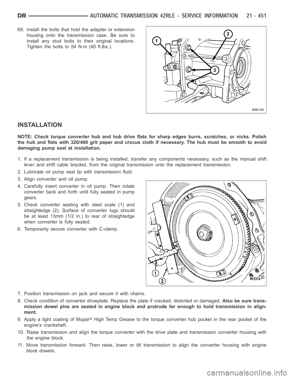
69. Install the bolts that hold the adapter or extension
housing onto the transmission case. Be sure to
install any stud bolts to their original locations.
Tighten the bolts to 54 Nꞏm (40 ft.lbs.).
INSTALLATION
NOTE: Check torque converter hub and hub drive flats for sharp edges burrs,scratches, or nicks. Polish
the hub and flats with 320/400 grit paper and crocus cloth if necessary. Thehub must be smooth to avoid
damaging pump seal at installation.
1. If a replacement transmission is being installed, transfer any components necessary, such as the manual shift
lever and shift cable bracket, from the original transmission onto the replacement transmission.
2. Lubricate oil pump seal lip with transmission fluid.
3. Align converter and oil pump.
4. Carefully insert converter in oil pump. Then rotate
converter back and forth until fully seated in pump
gears.
5. Check converter seating with steel scale (1) and
straightedge (2). Surface of converter lugs should
be at least 13mm (1/2 in.) to rear of straightedge
when converter is fully seated.
6. Temporarily secure converter with C-clamp.
7. Position transmission on jack and secure it with chains.
8. Check condition of converter driveplate. Replace the plate if cracked,distorted or damaged.Also be sure trans-
mission dowel pins are seated in engine block and protrude far enough to holdtransmissioninalign-
ment.
9. Apply a light coating of Mopar
High Temp Grease to the torque converter hub pocket in the rear pocket of the
engine’s crankshaft.
10. Raise transmission and align the torque converter with the drive plateand transmission converter housing with
the engine block.
11. Move transmission forward. Then raise, lower or tilt transmission to align the converter housing with engine
block dowels.
Page 3014 of 5267
FLUID AND FILTER
DIAGNOSIS AND TESTING
CAUSES OF BURNT FLUID
Burnt, discolored fluid is a result of overheating which has two primary causes.
1. A result of restricted fluid flow through the main and/or auxiliary cooler. This condition is usually the result of a
faulty or improperly installed drainback valve, a damaged oil cooler, or severe restrictions in the coolers and lines
caused by debris or kinked lines.
2. Heavy duty operation with a vehicle not properly equipped for this type of operation. Trailer towing or similar high
load operation will overheat the transmission fluid if the vehicle is improperly equipped. Such vehicles should
have an auxiliary transmission fluid cooler, a heavy duty cooling system,and the engine/axle ratio combination
needed to handle heavy loads.
EFFECTS OF INCORRECT FLUID LEVEL
Alowfluidlevelallowsthepumptotakeinairalongwiththefluid.Airinthe fluid will cause fluid pressures to be
low and develop slower than normal. If the transmission is overfilled, thegears churn the fluid into foam. This aer-
ates the fluid and causing the same conditions occurring with a low level. In either case, air bubbles cause fluid
overheating, oxidation, and varnish buildup which interferes with valveand clutch operation. Foaming also causes
fluid expansion which can result in fluid overflow from the transmission vent or fill tube. Fluid overflow can easily be
mistaken for a leak if inspection is not careful.
FLUID CONTAMINATION
Transmission fluid contamination is generally a result of:
adding incorrect fluid
failure to clean dipstick and fill tube when checking level
engine coolant entering the fluid
internal failure that generates debris
overheat that generates sludge (fluid breakdown)
failure to replace contaminated converter after repair
The use of non-recommended fluids can result in transmission failure. Theusual results are erratic shifts, slippage,
abnormal wear and eventual failure due to fluid breakdown and sludge formation. Avoid this condition by using rec-
ommended fluids only.
The dipstick cap and fill tube should be wiped clean before checking fluid level. Dirt, grease and other foreign mate-
rial on the cap and tube could fall into the tube if not removed beforehand. Take the time to wipe the cap and tube
clean before withdrawing the dipstick.
Engine coolant in the transmission fluid is generally caused by a cooler malfunction. The only remedy is to replace
the radiator as the cooler in the radiator is not a serviceable part. If coolant has circulated through the transmission,
an overhaul is necessary.
The torque converter should also be replaced whenever a failure generatessludge and debris. This is necessary
because normal converter flushing procedures will not remove all contaminants.
STANDARD PROCEDURE
FLUID LEVEL CHECK
The transmission sump has a dipstick to check oil similar to most automatictransmissions. It is located on the left
side of the engine. Be sure to wipe all dirt from dipstick handle before removing.
The torque converter fills in both the PARK and NEUTRAL positions. Place the selector lever in PARK to be sure
that the fluid level check is accurate.The engine should be running at idle speed for at least one minute, with
the vehicle on level ground.At normal operating temperature (approximately 82° C or 180° F), the fluidlevel is
correct if it is in the HOT region (cross-hatched area) on the oil level indicator. The fluid level should be in COLD
region at 21° C (70° F) fluid temperature. Adjust fluid level as necessary.Use only Mopar
ATF+4, Automatic Trans-
mission Fluid.