DODGE RAM SRT-10 2006 Service Repair Manual
RAM SRT-10 2006
DODGE
DODGE
https://www.carmanualsonline.info/img/12/56917/w960_56917-0.png
DODGE RAM SRT-10 2006 Service Repair Manual
Trending: wiring diagram, dimensions, roof, timing belt, check transmission fluid, automatic transmission fluid, fuel tank capacity
Page 4181 of 5267
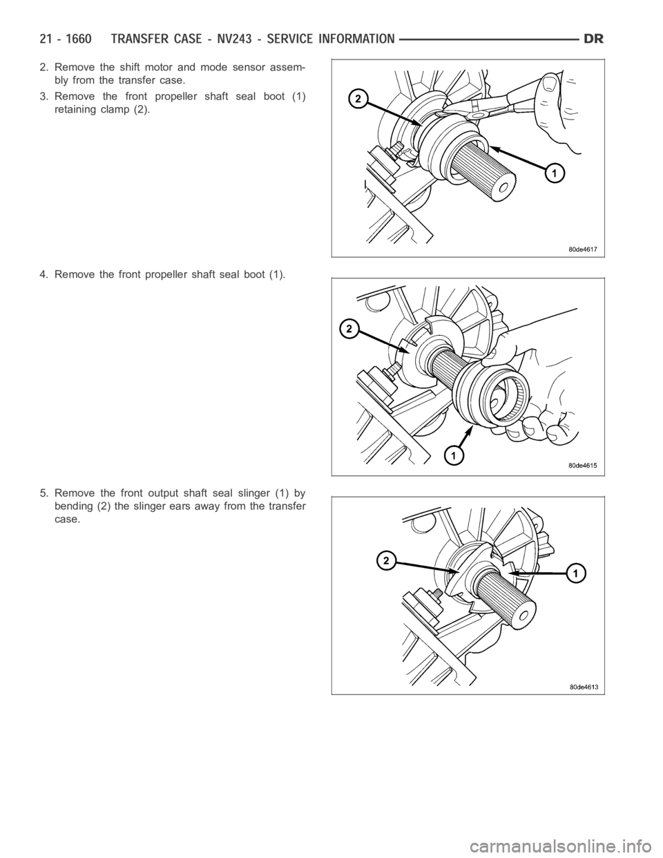
2. Remove the shift motor and mode sensor assem-
bly from the transfer case.
3. Remove the front propeller shaft seal boot (1)
retaining clamp (2).
4. Remove the front propeller shaft seal boot (1).
5. Remove the front output shaft seal slinger (1) by
bending (2) the slinger ears away from the transfer
case.
Page 4182 of 5267
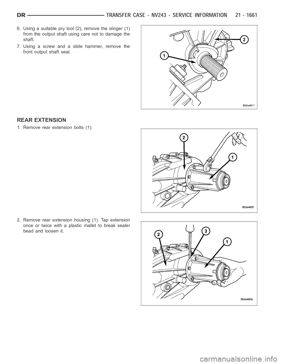
6. Using a suitable pry tool (2), remove the slinger (1)
from the output shaft using care not to damage the
shaft.
7. Using a screw and a slide hammer, remove the
front output shaft seal.
REAR EXTENSION
1. Remove rear extension bolts (1).
2. Remove rear extension housing (1). Tap extension
once or twice with a plastic mallet to break sealer
bead and loosen it.
Page 4183 of 5267
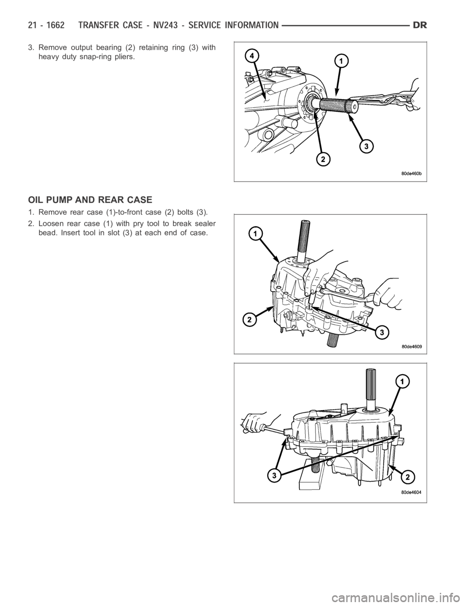
3. Remove output bearing (2) retaining ring (3) with
heavy duty snap-ring pliers.
OIL PUMP AND REAR CASE
1. Remove rear case (1)-to-front case (2) bolts (3).
2. Loosen rear case (1) with pry tool to break sealer
bead. Insert tool in slot (3) at each end of case.
Page 4184 of 5267
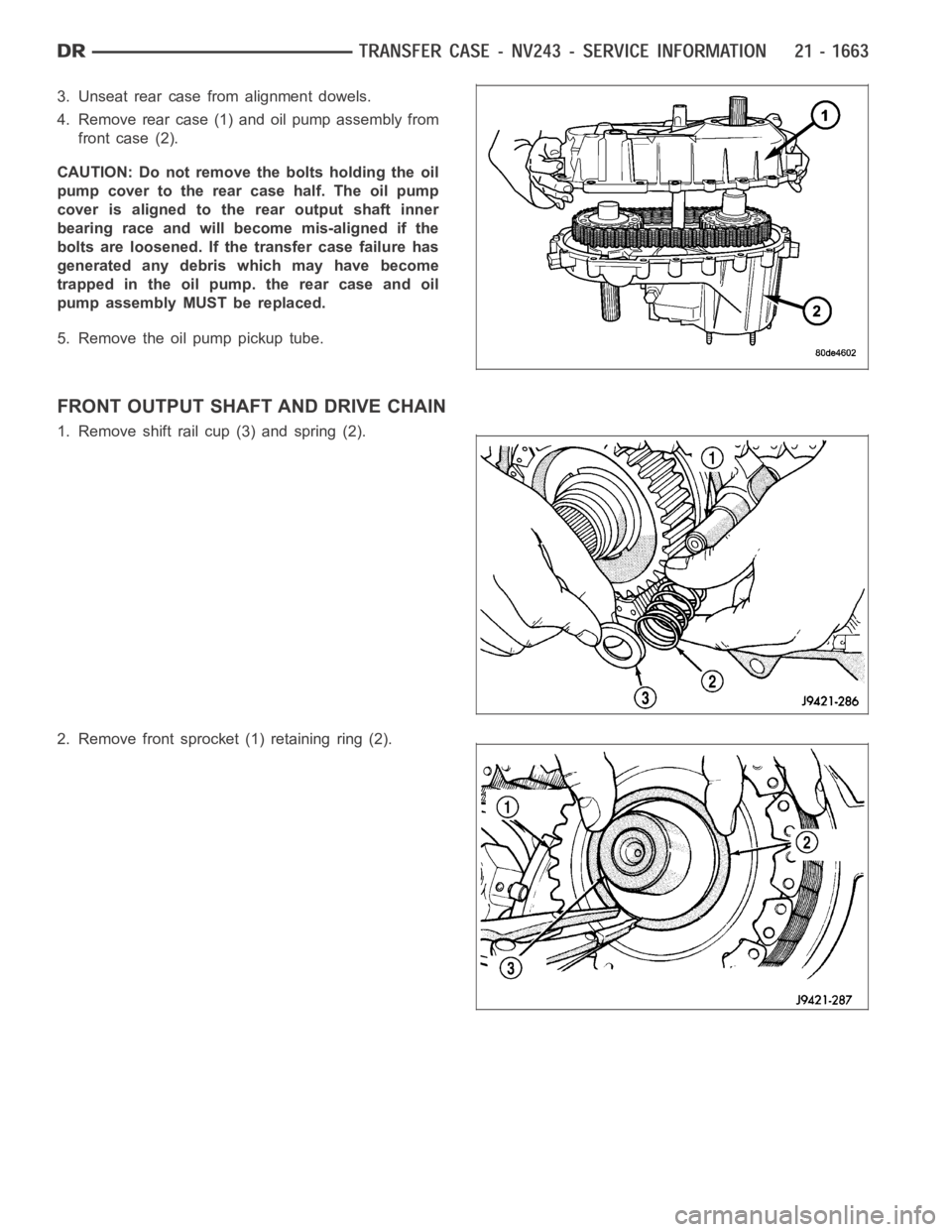
3. Unseat rear case from alignment dowels.
4. Remove rear case (1) and oil pump assembly from
front case (2).
CAUTION: Do not remove the bolts holding the oil
pump cover to the rear case half. The oil pump
cover is aligned to the rear output shaft inner
bearing race and will become mis-aligned if the
bolts are loosened. If the transfer case failure has
generated any debris which may have become
trapped in the oil pump. the rear case and oil
pump assembly MUST be replaced.
5. Remove the oil pump pickup tube.
FRONT OUTPUT SHAFT AND DRIVE CHAIN
1. Remove shift rail cup (3) and spring (2).
2. Remove front sprocket (1) retaining ring (2).
Page 4185 of 5267
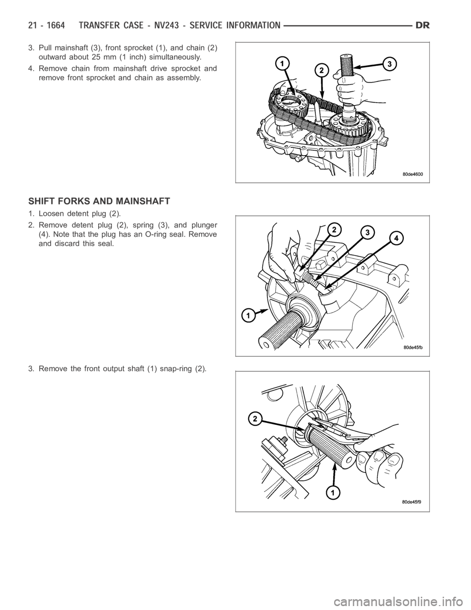
3. Pull mainshaft (3), front sprocket (1), and chain (2)
outward about 25 mm (1 inch) simultaneously.
4. Remove chain from mainshaft drive sprocket and
remove front sprocket and chain as assembly.
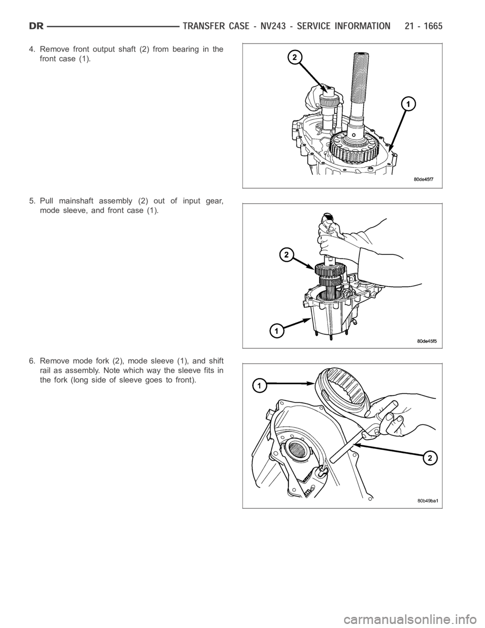
SHIFT FORKS AND MAINSHAFT
1. Loosen detent plug (2).
2. Remove detent plug (2), spring (3), and plunger
(4). Note that the plug has an O-ring seal. Remove
and discard this seal.
3. Remove the front output shaft (1) snap-ring (2).
Page 4186 of 5267
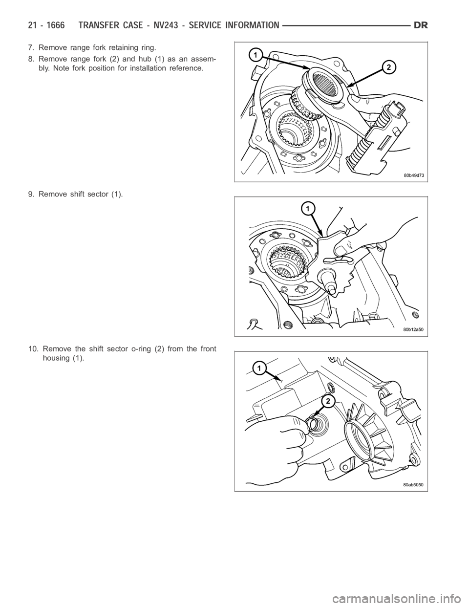
4. Remove front output shaft (2) from bearing in the
front case (1).
5. Pull mainshaft assembly (2) out of input gear,
mode sleeve, and front case (1).
6. Remove mode fork (2), mode sleeve (1), and shift
rail as assembly. Note which way the sleeve fits in
the fork (long side of sleeve goes to front).
Page 4187 of 5267
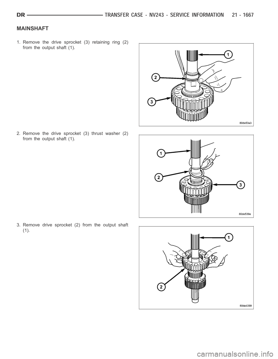
7. Remove range fork retaining ring.
8. Remove range fork (2) and hub (1) as an assem-
bly. Note fork position for installation reference.
9. Remove shift sector (1).
10. Remove the shift sector o-ring (2) from the front
housing (1).
Page 4188 of 5267
MAINSHAFT
1. Remove the drive sprocket (3) retaining ring (2)
from the output shaft (1).
2. Remove the drive sprocket (3) thrust washer (2)
from the output shaft (1).
3. Remove drive sprocket (2) from the output shaft
(1).
Page 4189 of 5267
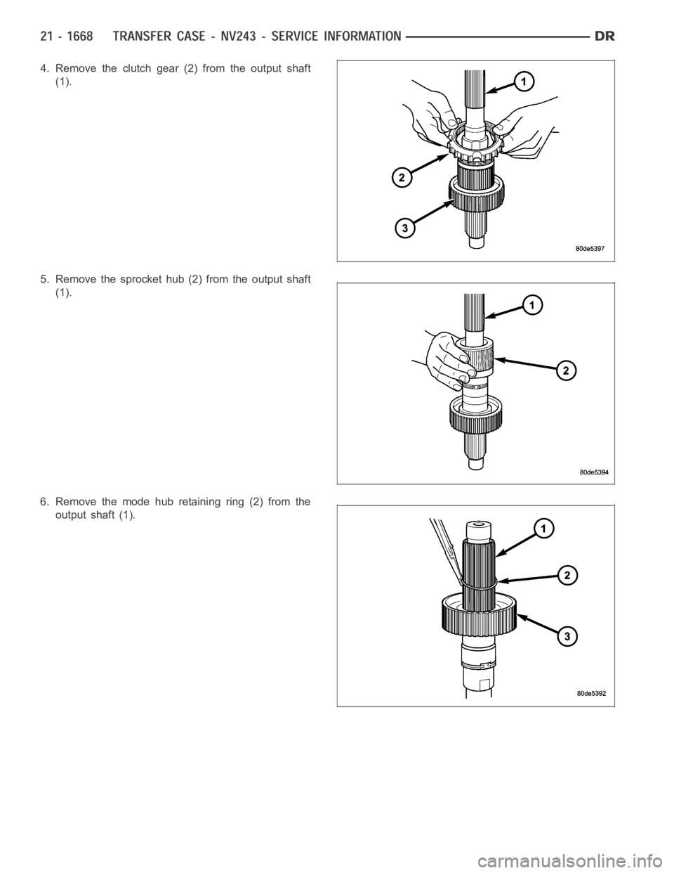
4. Remove the clutch gear (2) from the output shaft
(1).
5. Remove the sprocket hub (2) from the output shaft
(1).
6. Remove the mode hub retaining ring (2) from the
output shaft (1).
Page 4190 of 5267
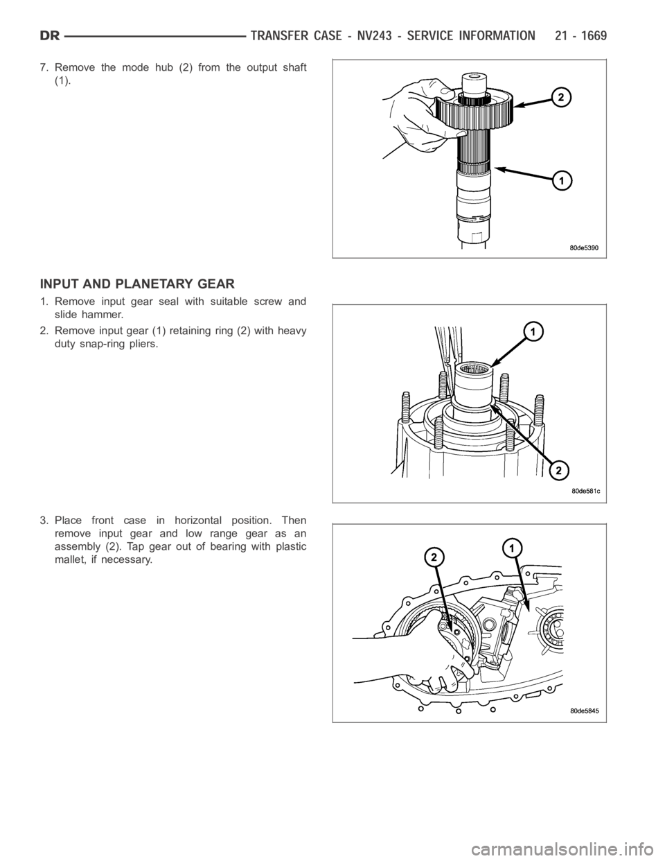
7. Remove the mode hub (2) from the output shaft
(1).
INPUT AND PLANETARY GEAR
1. Remove input gear seal with suitable screw and
slide hammer.
2. Remove input gear (1) retaining ring (2) with heavy
duty snap-ring pliers.
3. Place front case in horizontal position. Then
remove input gear and low range gear as an
assembly (2). Tap gear out of bearing with plastic
mallet, if necessary.
Trending: airbag disable, parking brake, window, battery, radiator, ABS, brake sensor
