DODGE RAM SRT-10 2006 Service Repair Manual
Manufacturer: DODGE, Model Year: 2006, Model line: RAM SRT-10, Model: DODGE RAM SRT-10 2006Pages: 5267, PDF Size: 68.7 MB
Page 4311 of 5267
For resistances between the ranges A and B shown for the fault condition (short) and T-Case NEUTRAL, the TCCM
may interpret the resistance as:
the T-Case NEUTRAL position.
an invalid fault position.
The LED’s in the selector assembly are illuminated/flashed in the following manner to indicate a particular condition
or state.
A solidly illuminated LED indicates asuccessfully completed shift and the current operating mode of the trans-
fer case. While a shift has been requested but not yet completed, the LED forthe desired transfer case posi-
tion is flashed.
A flashing operating mode LED for the desired gear indicates that a shift tothat position has been requested,
but all of the driver controllable conditions have not been met. This is in an attempt to notify the driver that the
transmission needs to be put into NEUTRAL, the vehicle speed is too great, or some other condition outlined
(other than a diagnostic failure that would prevent this shift) elsewhere(Refer to 8 - ELECTRICAL/ELEC-
TRONIC CONTROL MODULES/TRANSFER CASE CONTROL MODULE - OPERATION) is not met. Note that
this flashing will continue indefinitely until the conditions are eventually met, or the selector switch position is
changed, or if diagnostic routines no longer allow the requested shift.
If the driver attempts to make a shift into transfer case NEUTRAL, and any ofthe driver controllable conditions
are not met, the request will be ignored until all of the conditions are met or until the NEUTRAL select button
is released. Additionally the neutral lamp will flash, or begin to flash while the button is depressed and operator
controllable conditions are not being met. All of the LED’s except the Neutral will flash if any of the operator
controllable conditions for shifting are not met while the Neutral buttonis depressed. This
toggletype of fea-
ture is necessary because the TCCM would interpret another request immediately after the shift into transfer
case NEUTRAL has completed.
No LED’s illuminated indicate a fault in the transfer case control system.
Page 4312 of 5267
MOTOR-SHIFT
DESCRIPTION
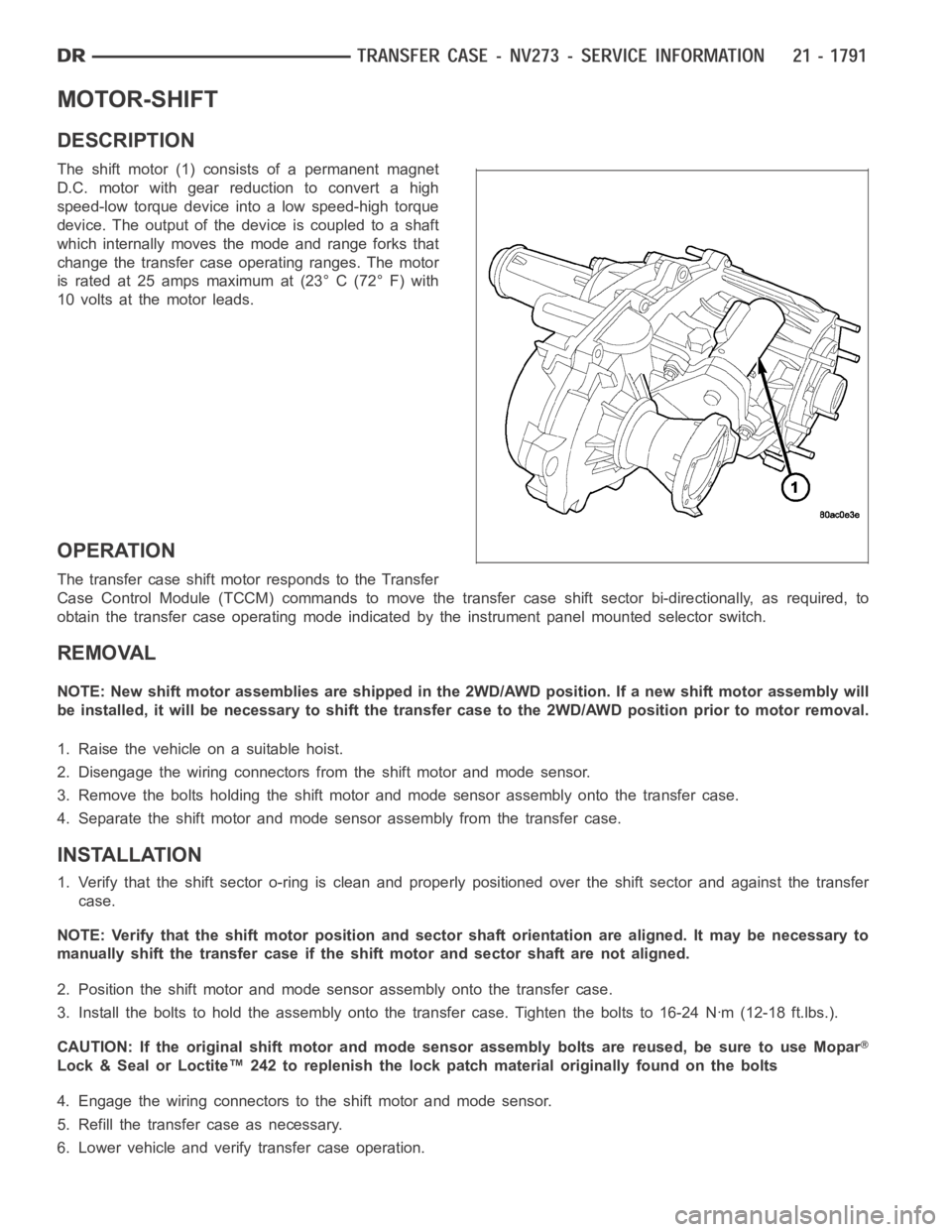
The shift motor (1) consists of a permanent magnet
D.C. motor with gear reduction to convert a high
speed-low torque device into a low speed-high torque
device. The output of the device is coupled to a shaft
which internally moves the mode and range forks that
change the transfer case operating ranges. The motor
is rated at 25 amps maximum at (23° C (72° F) with
10 volts at the motor leads.
OPERATION
The transfer case shift motor responds to the Transfer
Case Control Module (TCCM) commands to move the transfer case shift sectorbi-directionally, as required, to
obtain the transfer case operating mode indicated by the instrument panelmounted selector switch.
REMOVAL
NOTE: New shift motor assemblies are shipped in the 2WD/AWD position. If a new shift motor assembly will
be installed, it will be necessary to shift the transfer case to the 2WD/AWDposition prior to motor removal.
1. Raise the vehicle on a suitable hoist.
2. Disengage the wiring connectors from the shift motor and mode sensor.
3. Remove the bolts holding the shift motor and mode sensor assembly onto the transfer case.
4. Separate the shift motor and mode sensor assembly from the transfer case.
INSTALLATION
1. Verify that the shift sector o-ring is clean and properly positioned over the shift sector and against the transfer
case.
NOTE: Verify that the shift motor position and sector shaft orientation are aligned. It may be necessary to
manually shift the transfer case if the shift motor and sector shaft are notaligned.
2. Position the shift motor and mode sensor assembly onto the transfer case.
3. Install the bolts to hold the assembly onto the transfer case. Tighten the bolts to 16-24 Nꞏm (12-18 ft.lbs.).
CAUTION: If the original shift motor and mode sensor assembly bolts are reused, be sure to use Mopar
Lock & Seal or Loctite™ 242 to replenish the lock patch material originallyfound on the bolts
4. Engage the wiring connectors to the shift motor and mode sensor.
5. Refill the transfer case as necessary.
6. Lower vehicle and verify transfer case operation.
Page 4313 of 5267

Page 4314 of 5267
TIRES/WHEELS
TABLE OF CONTENTS
page page
TIRES/WHEELS
DIAGNOSIS AND TESTING
TIRE AND WHEEL RUNOUT .................. 2
STANDARD PROCEDURE
MATCH MOUNTING .......................... 4
TIRE AND WHEEL BALANCE ................. 5
TIRE ROTATION ............................. 6
SPECIFICATIONS
TORQUE .................................... 7
TIRES
DESCRIPTION
TIRES ....................................... 8
SPARE / TEMPORARY TIRE .................. 8
RADIAL – PLY TIRES ......................... 8
TIRE PRESSURE FOR HIGH SPEEDS......... 9
REPLACEMENT TIRES ....................... 9
TIRE INFLATION PRESSURES ................ 9
DIAGNOSIS AND TESTING
PRESSURE GAUGES ....................... 10
TIRE NOISE OR VIBRATION ................. 10
TREAD WEAR INDICATORS ................. 10
TIRE WEAR PATTERNS ..................... 11
TIRE/VEHICLE LEAD ........................ 12
STANDARD PROCEDURE
TIRE REPAIR AREA ......................... 13
CLEANING
TIRES ..................................... 13SPECIFICATIONS
TIRE REVOLUTIONS PER MILE .............. 13
WHEELS
DESCRIPTION
DESCRIPTION .............................. 15
WHEEL DESIGN ............................ 16
DIAGNOSIS AND TESTING
WHEEL INSPECTION....................... 16
STANDARD PROCEDURE
WHEEL REPLACEMENT ..................... 16
DUAL REAR WHEEL INSTALLATION .......... 18
STUDS
REMOVAL .................................... 20
INSTALLATION ............................... 20
WHEEL COVER
REMOVAL .................................... 22
INSTALLATION
REAR ...................................... 22
FRONT .................................... 22
SPARE TIRE
DESCRIPTION
SPARE / TEMPORARY TIRE ................. 23
FULL SIZE, SPARE WHEEL WITH
MATCHING TIRE............................ 23
Page 4315 of 5267
TIRES/WHEELS
DIAGNOSIS AND TESTING
TIRE AND WHEEL RUNOUT
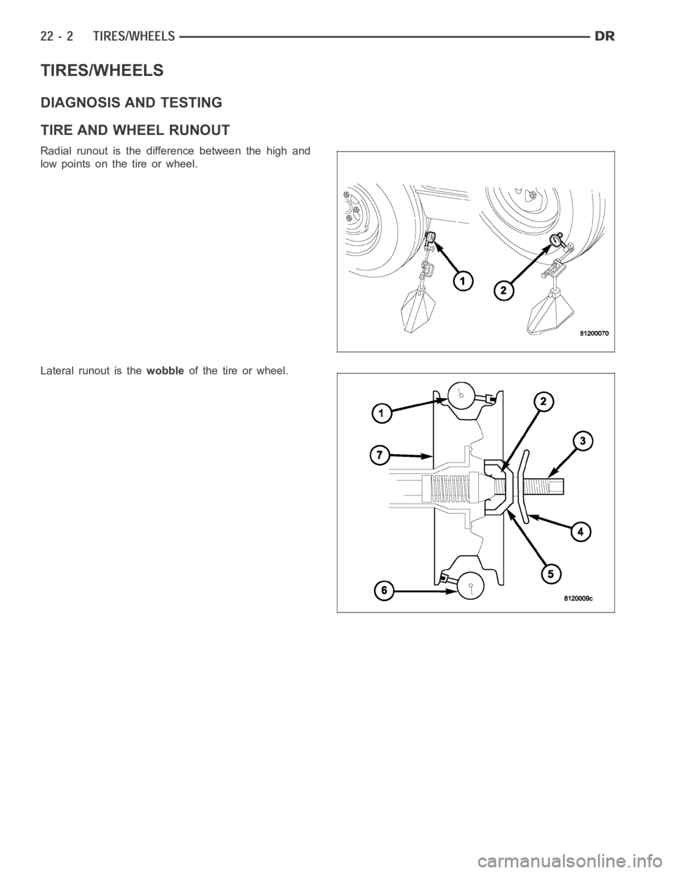
Radial runout is the difference between the high and
low points on the tire or wheel.
Lateral runout is thewobbleof the tire or wheel.
Page 4316 of 5267
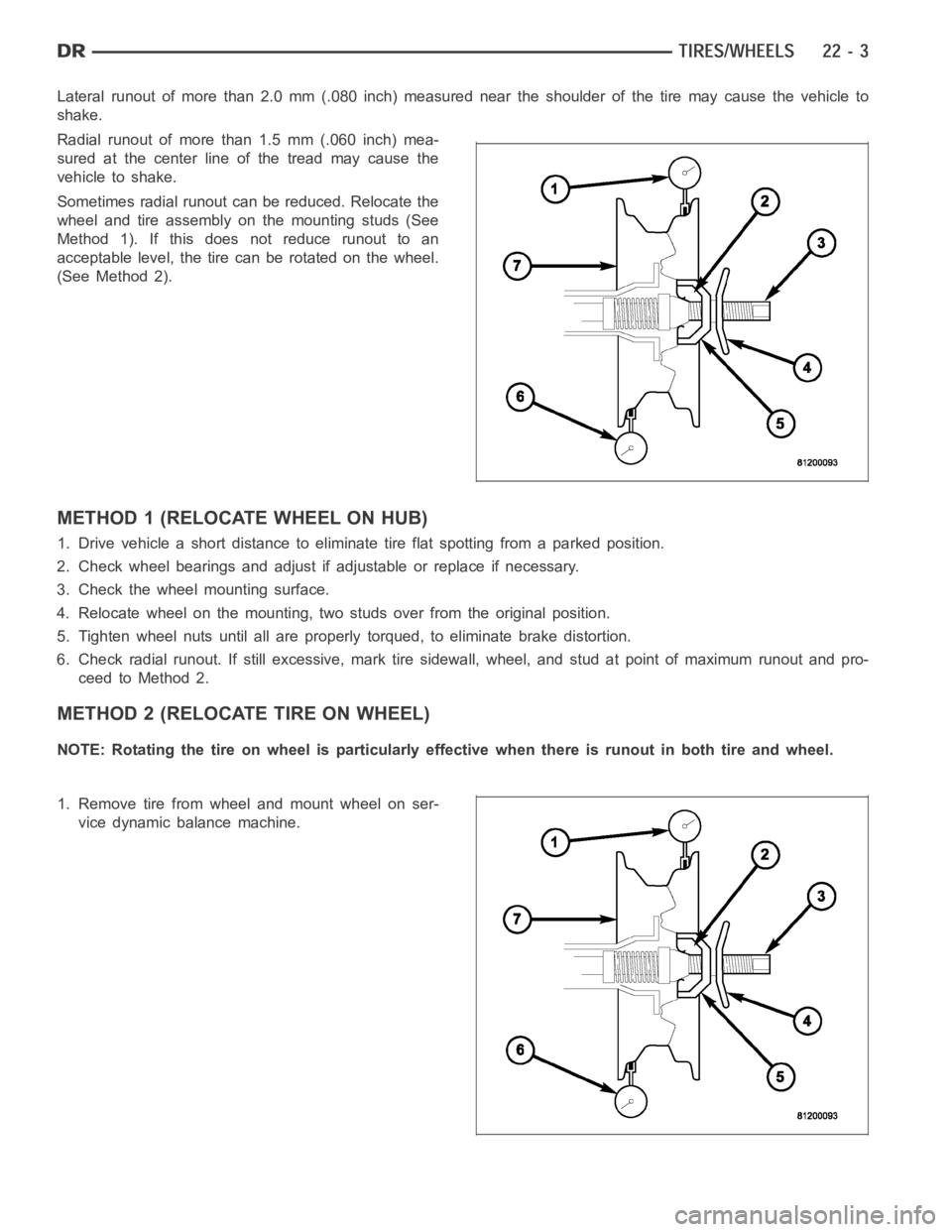
Lateral runout of more than 2.0 mm (.080 inch) measured near the shoulder ofthetiremaycausethevehicleto
shake.
Radial runout of more than 1.5 mm (.060 inch) mea-
sured at the center line of the tread may cause the
vehicle to shake.
Sometimes radial runout can be reduced. Relocate the
wheel and tire assembly on the mounting studs (See
Method 1). If this does not reduce runout to an
acceptable level, the tire can be rotated on the wheel.
(See Method 2).
METHOD 1 (RELOCATE WHEEL ON HUB)
1. Drive vehicle a short distance to eliminate tire flat spotting from a parked position.
2. Check wheel bearings and adjust if adjustable or replace if necessary.
3. Check the wheel mounting surface.
4. Relocate wheel on the mounting, two studs over from the original position.
5. Tighten wheel nuts until all are properly torqued, to eliminate brake distortion.
6. Check radial runout. If still excessive, mark tire sidewall, wheel, andstud at point of maximum runout and pro-
ceed to Method 2.
METHOD 2 (RELOCATE TIRE ON WHEEL)
NOTE: Rotating the tire on wheel is particularly effective when there is runout in both tire and wheel.
1. Remove tire from wheel and mount wheel on ser-
vice dynamic balance machine.
Page 4317 of 5267
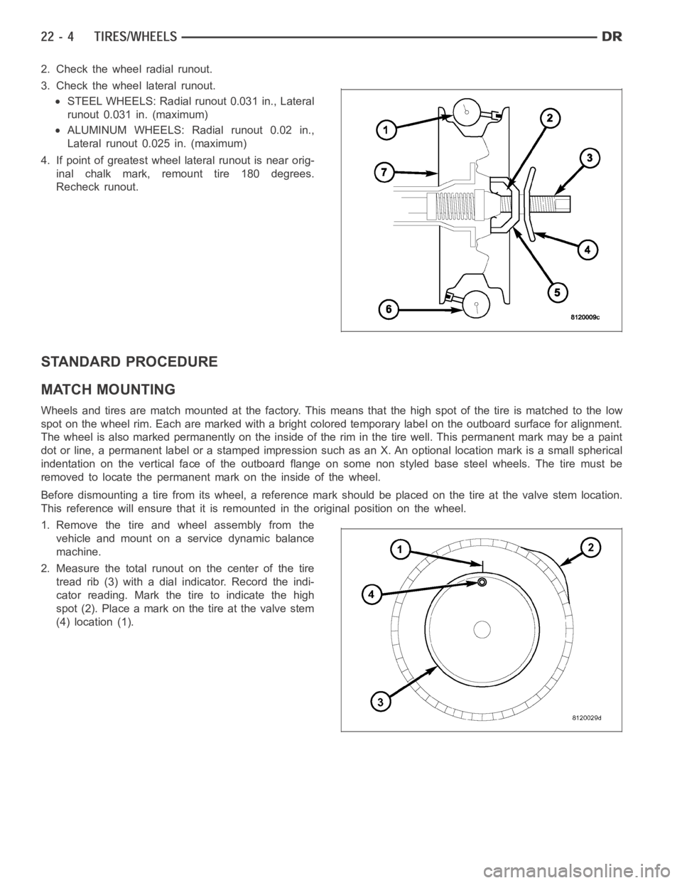
2. Check the wheel radial runout.
3. Check the wheel lateral runout.
STEEL WHEELS: Radial runout 0.031 in., Lateral
runout 0.031 in. (maximum)
ALUMINUM WHEELS: Radial runout 0.02 in.,
Lateral runout 0.025 in. (maximum)
4. If point of greatest wheel lateral runout is near orig-
inal chalk mark, remount tire 180 degrees.
Recheck runout.
STANDARD PROCEDURE
MATCH MOUNTING
Wheels and tires are match mounted at the factory. This means that the high spot of the tire is matched to the low
spot on the wheel rim. Each are marked with a bright colored temporary labelon the outboard surface for alignment.
The wheel is also marked permanently on the inside of the rim in the tire well. This permanent mark may be a paint
dot or line, a permanent label or a stamped impression such as an X. An optional location mark is a small spherical
indentation on the vertical face of the outboard flange on some non styled base steel wheels. The tire must be
removed to locate the permanent mark on the inside of the wheel.
Before dismounting a tire from its wheel, a reference mark should be placedon the tire at the valve stem location.
This reference will ensure that it is remounted in the original position onthe wheel.
1. Remove the tire and wheel assembly from the
vehicle and mount on a service dynamic balance
machine.
2. Measure the total runout on the center of the tire
tread rib (3) with a dial indicator. Record the indi-
cator reading. Mark the tire to indicate the high
spot (2). Place a mark on the tire at the valve stem
(4) location (1).
Page 4318 of 5267
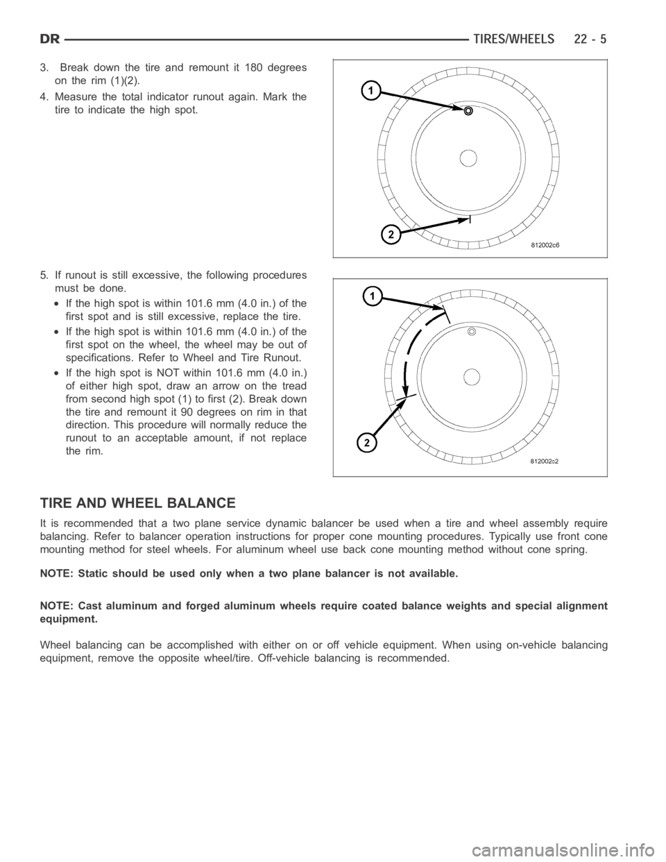
3. Break down the tire and remount it 180 degrees
on the rim (1)(2).
4. Measure the total indicator runout again. Mark the
tire to indicate the high spot.
5. If runout is still excessive, the following procedures
must be done.
If the high spot is within 101.6 mm (4.0 in.) of the
first spot and is still excessive, replace the tire.
If the high spot is within 101.6 mm (4.0 in.) of the
first spot on the wheel, the wheel may be out of
specifications. Refer to Wheel and Tire Runout.
IfthehighspotisNOTwithin101.6mm(4.0in.)
of either high spot, draw an arrow on the tread
from second high spot (1) to first (2). Break down
the tire and remount it 90 degrees on rim in that
direction. This procedure will normally reduce the
runout to an acceptable amount, if not replace
the rim.
TIRE AND WHEEL BALANCE
It is recommended that a two plane service dynamic balancer be used when a tire and wheel assembly require
balancing. Refer to balancer operation instructions for proper cone mounting procedures. Typically use front cone
mounting method for steel wheels. For aluminum wheel use back cone mounting method without cone spring.
NOTE: Static should be used only when a two plane balancer is not available.
NOTE: Cast aluminum and forged aluminum wheels require coated balance weights and special alignment
equipment.
Wheel balancing can be accomplished with either on or off vehicle equipment. When using on-vehicle balancing
equipment, remove the opposite wheel/tire. Off-vehicle balancing is recommended.
Page 4319 of 5267
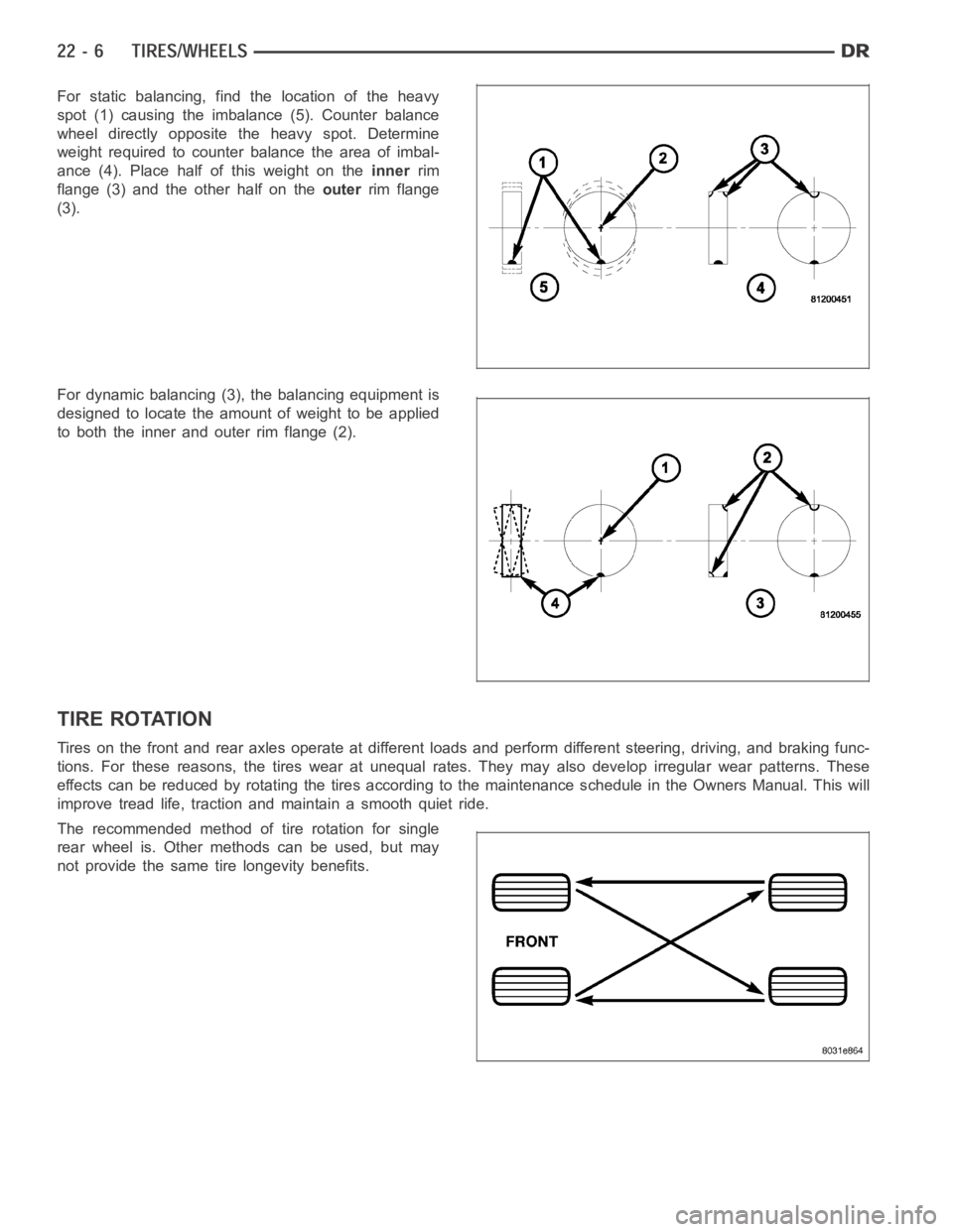
For static balancing, find the location of the heavy
spot (1) causing the imbalance (5). Counter balance
wheel directly opposite the heavy spot. Determine
weight required to counter balance the area of imbal-
ance (4). Place half of this weight on theinnerrim
flange (3) and the other half on theouterrim flange
(3).
For dynamic balancing (3), the balancing equipment is
designed to locate the amount of weight to be applied
to both the inner and outer rim flange (2).
TIRE ROTATION
Tires on the front and rear axles operate at different loads and perform different steering, driving, and braking func-
tions. For these reasons, the tires wear at unequal rates. They may also develop irregular wear patterns. These
effects can be reduced by rotating the tires according to the maintenance schedule in the Owners Manual. This will
improve tread life, traction and maintain a smooth quiet ride.
The recommended method of tire rotation for single
rear wheel is. Other methods can be used, but may
not provide the same tire longevity benefits.
Page 4320 of 5267
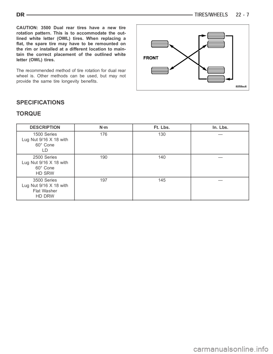
CAUTION: 3500 Dual rear tires have a new tire
rotation pattern. This is to accommodate the out-
lined white letter (OWL) tires. When replacing a
flat, the spare tire may have to be remounted on
the rim or installed at a different location to main-
tain the correct placement of the outlined white
letter (OWL) tires.
The recommended method of tire rotation for dual rear
wheel is. Other methods can be used, but may not
provide the same tire longevity benefits.
SPECIFICATIONS
TORQUE
DESCRIPTION Nꞏm Ft. Lbs. In. Lbs.
1500 Series
Lug Nut 9/16 X 18 with
60° Cone
LD176 130 —
2500 Series
Lug Nut 9/16 X 18 with
60° Cone
HD SRW190 140 —
3500 Series
Lug Nut 9/16 X 18 with
Flat Washer
HD DRW197 145 —