DODGE RAM SRT-10 2006 Service Repair Manual
Manufacturer: DODGE, Model Year: 2006, Model line: RAM SRT-10, Model: DODGE RAM SRT-10 2006Pages: 5267, PDF Size: 68.7 MB
Page 441 of 5267

9.STARTER
If there are no other possible causes remaining, review repair.
Repair
Replace the Starter.
Perform the POWERTRAIN VERIFICATION TEST. (Refer to 9 - ENGINE - STANDARD PROCEDURE)
Page 442 of 5267

*NO RESPONSE WITH A NO START CONDITION
For a complete wiring diagramRefer to Section 8W.
Page 443 of 5267
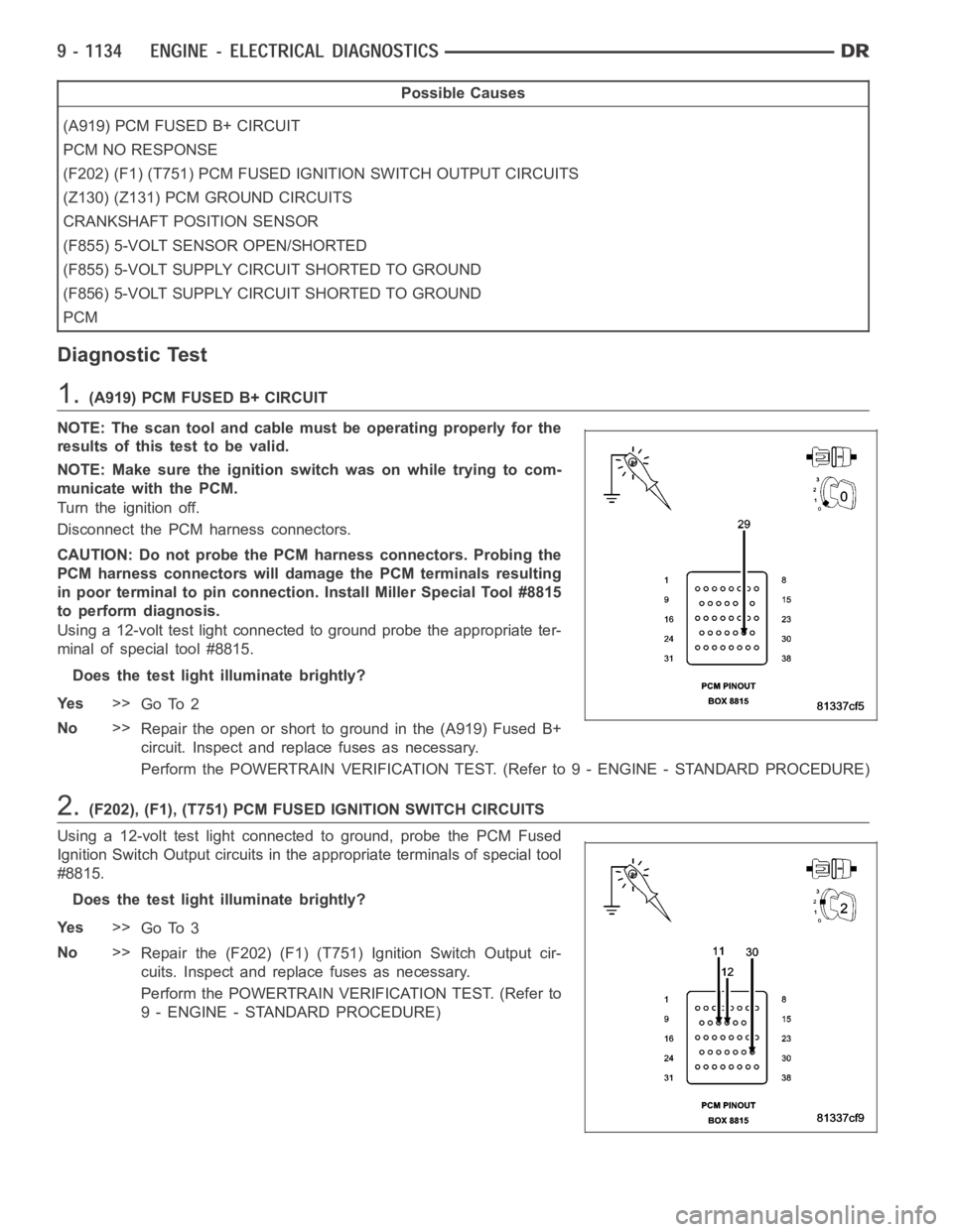
Possible Causes
(A919) PCM FUSED B+ CIRCUIT
PCM NO RESPONSE
(F202) (F1) (T751) PCM FUSED IGNITION SWITCH OUTPUT CIRCUITS
(Z130) (Z131) PCM GROUND CIRCUITS
CRANKSHAFT POSITION SENSOR
(F855) 5-VOLT SENSOR OPEN/SHORTED
(F855) 5-VOLT SUPPLY CIRCUIT SHORTED TO GROUND
(F856) 5-VOLT SUPPLY CIRCUIT SHORTED TO GROUND
PCM
Diagnostic Test
1.(A919) PCM FUSED B+ CIRCUIT
NOTE: The scan tool and cable must be operating properly for the
resultsofthistesttobevalid.
NOTE: Make sure the ignition switch was on while trying to com-
municate with the PCM.
Turn the ignition off.
Disconnect the PCM harness connectors.
CAUTION: Do not probe the PCM harness connectors. Probing the
PCM harness connectors will damage the PCM terminals resulting
in poor terminal to pin connection. Install Miller Special Tool #8815
to perform diagnosis.
Using a 12-volt test light connected to ground probe the appropriate ter-
minal of special tool #8815.
Does the test light illuminate brightly?
Ye s>>
Go To 2
No>>
Repair the open or short to ground in the (A919) Fused B+
circuit. Inspect and replace fuses as necessary.
Perform the POWERTRAIN VERIFICATION TEST. (Refer to 9 - ENGINE - STANDARD PROCEDURE)
2.(F202), (F1), (T751) PCM FUSED IGNITION SWITCH CIRCUITS
Using a 12-volt test light connected to ground, probe the PCM Fused
Ignition Switch Output circuits in the appropriate terminals of special tool
#8815.
Does the test light illuminate brightly?
Ye s>>
Go To 3
No>>
Repair the (F202) (F1) (T751) Ignition Switch Output cir-
cuits. Inspect and replace fuses as necessary.
Perform the POWERTRAIN VERIFICATION TEST. (Refer to
9 - ENGINE - STANDARD PROCEDURE)
Page 444 of 5267
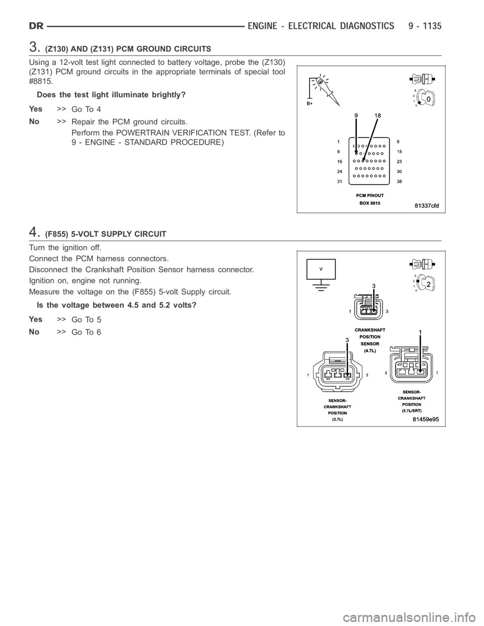
3.(Z130) AND (Z131) PCM GROUND CIRCUITS
Using a 12-volt test light connected to battery voltage, probe the (Z130)
(Z131) PCM ground circuits in the appropriate terminals of special tool
#8815.
Does the test light illuminate brightly?
Ye s>>
Go To 4
No>>
Repair the PCM ground circuits.
Perform the POWERTRAIN VERIFICATION TEST. (Refer to
9 - ENGINE - STANDARD PROCEDURE)
4.(F855) 5-VOLT SUPPLY CIRCUIT
Turn the ignition off.
Connect the PCM harness connectors.
Disconnect the Crankshaft Position Sensor harness connector.
Ignition on, engine not running.
Measure the voltage on the (F855) 5-volt Supply circuit.
Is the voltage between 4.5 and 5.2 volts?
Ye s>>
Go To 5
No>>
Go To 6
Page 445 of 5267
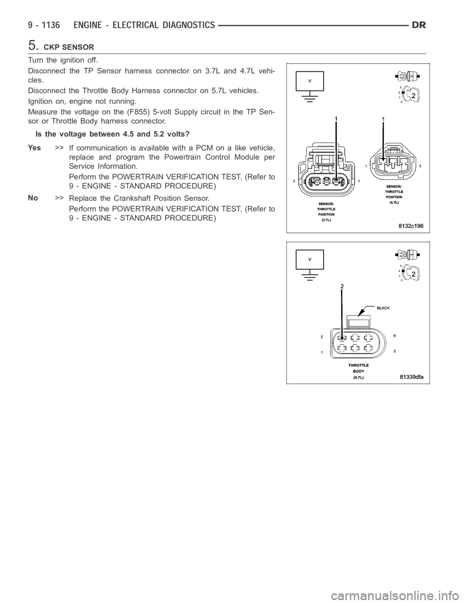
5.CKP SENSOR
Turn the ignition off.
Disconnect the TP Sensor harness connector on 3.7L and 4.7L vehi-
cles.
Disconnect the Throttle Body Harness connector on 5.7L vehicles.
Ignition on, engine not running.
Measure the voltage on the (F855) 5-volt Supply circuit in the TP Sen-
sor or Throttle Body harness connector.
Is the voltage between 4.5 and 5.2 volts?
Ye s>>
If communication is available with a PCM on a like vehicle,
replace and program the Powertrain Control Module per
Service Information.
Perform the POWERTRAIN VERIFICATION TEST. (Refer to
9 - ENGINE - STANDARD PROCEDURE)
No>>
Replace the Crankshaft Position Sensor.
Perform the POWERTRAIN VERIFICATION TEST. (Refer to
9 - ENGINE - STANDARD PROCEDURE)
Page 446 of 5267
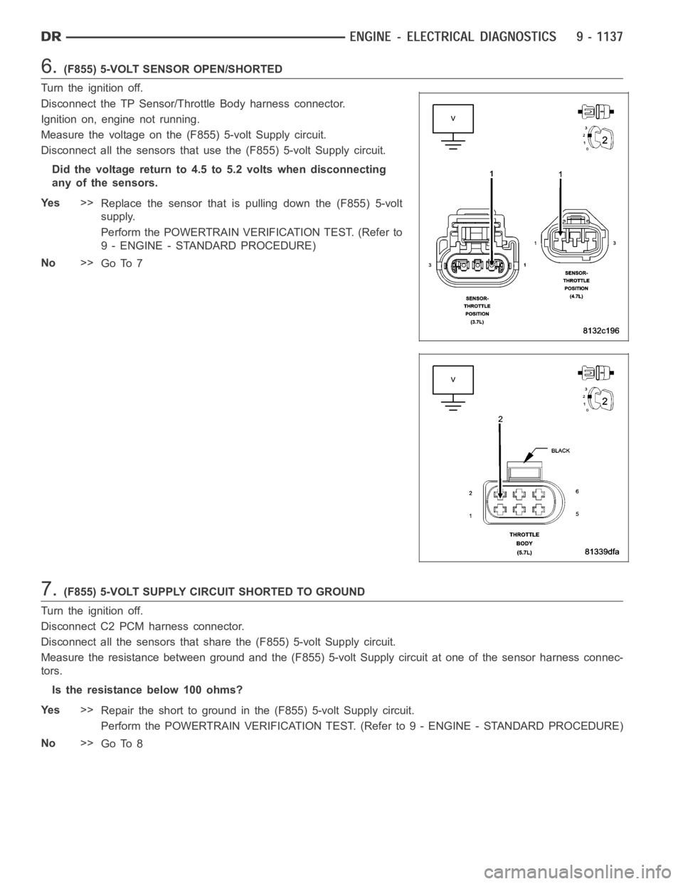
6.(F855) 5-VOLT SENSOR OPEN/SHORTED
Turn the ignition off.
Disconnect the TP Sensor/Throttle Body harness connector.
Ignition on, engine not running.
Measure the voltage on the (F855) 5-volt Supply circuit.
Disconnect all the sensors that use the (F855) 5-volt Supply circuit.
Did the voltage return to 4.5 to 5.2 volts when disconnecting
any of the sensors.
Ye s>>
Replace the sensor that is pulling down the (F855) 5-volt
supply.
Perform the POWERTRAIN VERIFICATION TEST. (Refer to
9 - ENGINE - STANDARD PROCEDURE)
No>>
Go To 7
7.(F855) 5-VOLT SUPPLY CIRCUIT SHORTED TO GROUND
Turn the ignition off.
Disconnect C2 PCM harness connector.
Disconnect all the sensors that share the (F855) 5-volt Supply circuit.
Measure the resistance between ground and the (F855) 5-volt Supply circuit at one of the sensor harness connec-
tors.
Istheresistancebelow100ohms?
Ye s>>
Repair the short to ground in the (F855) 5-volt Supply circuit.
Perform the POWERTRAIN VERIFICATION TEST. (Refer to 9 - ENGINE - STANDARD PROCEDURE)
No>>
Go To 8
Page 447 of 5267
8.(F856) 5-VOLT SUPPLY CIRCUIT SHORTED TO GROUND
Disconnect all the sensors that share the (F856) 5-volt Supply circuit.
Measure the resistance between ground and the (F856) 5-volt Supply circuit at one of the sensor harness connec-
tors.
Istheresistancebelow100ohms?
Ye s>>
Repair the short to ground in the (F856) 5-volt Supply circuit.
Perform the POWERTRAIN VERIFICATION TEST. (Refer to 9 - ENGINE - STANDARD PROCEDURE)
No>>
Go To 9
9.PCM
NOTE: Before continuing, check the PCM harness connector terminals for corrosion, damage, or terminal
push out. Repair as necessary.
Using the schematics as a guide, inspect the wire harness and connectors. Pay particular attention to all Power and
Ground circuits.
Were there any problems found?
Ye s>>
Repair as necessary.
Perform the POWERTRAIN VERIFICATION TEST. (Refer to 9 - ENGINE - STANDARD PROCEDURE)
No>>
Replace and program the Powertrain Control Module per Service Information.
Perform the POWERTRAIN VERIFICATION TEST. (Refer to 9 - ENGINE - STANDARD PROCEDURE)
Page 448 of 5267
*START AND STALL CONDITION
For a complete wiring diagramRefer to Section 8W.
Possible Causes
CURRENT PCM DTCS
CURRENT SKIM DTCS
THROTTLE POSITION SENSOR SWEEP
TP SENSOR NO.1 VOLTAGE GREATER THAN 0.92 VOLTS WITH THROTTLE CLOSED
ECT SENSOR
OTHER POSSIBLE CAUSES FOR START AND STALL CONDITON
FUEL CONTAMINATION
Diagnostic Test
1.CHECKING DTCS
Ignition on, engine not running.
With a scan tool, read DTCs.
Are any DTCs present?
Ye s>>
Refer to the appropriate Diagnostic Procedure.
Perform the POWERTRAIN VERIFICATION TEST. (Refer to 9 - ENGINE - STANDARD PROCEDURE)
No>>
Go To 2
2.CHECKING SKREEM DTCS
NOTE: If you are unable to communicate with the SKIM/SKREEM, refer to the VEHICLE THEFT AND SECU-
RITY ELECTRICAL DIAGNOSTICS in Section 8 and perform the appropriate diagnostics.
With the scan tool, read the SKIM codes.
Are there any SKIM DTCs?
Ye s>>
Refer to the Sentry Key Vehicle Theft Security Electrical Diagnostics in Section 8.
Perform the POWERTRAIN VERIFICATION TEST. (Refer to 9 - ENGINE - STANDARD PROCEDURE)
No>>
Go To 3
3.TP SENSOR SWEEP
Ignition on, engine not running.
With the scan tool read TP Sensor voltage.
While monitoring the scan tool, slowly open and close the Throttle on vehicles equipped with a 3.7L or 4.7L engine.
On vehicles equipped with a 5.7L engine, using a scan tool perform the pedalfollower test and monitor both TP
Sensor voltage readings.
Was the voltage change smooth?
Ye s>>
Go To 4
No>>
Replace the Throttle Position Sensor on a 3.7L and 4.7L engines or the Throttle Body Assembly on a
5.7L engine.
Perform the POWERTRAIN VERIFICATION TEST. (Refer to 9 - ENGINE - STANDARD PROCEDURE)
Page 449 of 5267
4.TP SENSOR NO.1 VOLTAGE GREATER THAN0.92 VOLTS WITH THROTTLE CLOSED
With the scan tool, read Throttle Position Sensor No.1 voltage.
Throttle must be against its stop.
Is the voltage 0.92 or less with the Throttle closed?
Ye s>>
Go To 5
No>>
Check for a binding throttle condition. If OK, replace the Throttle Position Sensor or the Throttle Body
Assemblyona5.7L.
Perform the POWERTRAIN VERIFICATION TEST. (Refer to 9 - ENGINE - STANDARD PROCEDURE)
5.ECT SENSOR OPERATION
NOTE: For this test to be valid, the thermostat must be operating correctly.
NOTE: This test works best if performed on a cold engine (cold soaked).
NOTE: If the vehicle was allowed to sit over night with no engine start, coolant temperature should be near
ambient temperatures.
Ignition on, engine not running.
With the scan tool, read the ECT value.
NOTE: If engine coolant temperature is above 82° C (180° F), allow the engine to cool until 65° C (150° F) is
reached.
Start the engine.
During engine warm-up, monitor the Engine Coolant Temperature value. Thetemperature value change should be a
smooth transition from start up to normal operating temp 82° C (180° F). Thevalue should reach at least 82° C
(180° F).
Did the Engine Temperature value increase smoothly and did it reach at least 82° C (180° F)?
Ye s>>
Go To 6
No>>
Replace the Engine Coolant Temperature Sensor.
Perform the POWERTRAIN VERIFICATION TEST. (Refer to 9 - ENGINE - STANDARD PROCEDURE)
6.OTHER POSSIBLE CAUSES OF START AND STALL CONDITION
The following additional items should be checked as a possible cause for a start and stall condition.
Refer to any Technical Service Bulletins (TSBs) that may apply to the symptom.
The exhaust system must be free of any restrictions.
The engine compression must be within specifications.
The engine valve timing must be within specifications.
Theenginemustbefreefromvacuumleaks.
The throttle body must be free of carbon buildup and dirt.
Do any of the above conditions exist?
Ye s>>
Repair as necessary.
Perform the POWERTRAIN VERIFICATION TEST. (Refer to 9 - ENGINE - STANDARD PROCEDURE)
No>>
Go To 7
Page 450 of 5267

7.FUEL PUMP DELIVERY
Verify that the Fuel tank is not empty before continuing.
Follow the diagnostics for Checking Fuel Delivery in this manual.
Was the No Start condition solved after following the above diagnostic test?
Ye s>>
Te s t C o m p l e t e .
No>>
Check for contamination/water in the fuel. Ensure the fuel being used in this vehicle meets manufac-
tures Fuel Requirement, refer to the service manual.
Perform the POWERTRAIN VERIFICATION TEST. (Refer to 9 - ENGINE - STANDARD PROCEDURE)
STANDARD PROCEDURE