DODGE RAM SRT-10 2006 Service Repair Manual
Manufacturer: DODGE, Model Year: 2006, Model line: RAM SRT-10, Model: DODGE RAM SRT-10 2006Pages: 5267, PDF Size: 68.7 MB
Page 5111 of 5267
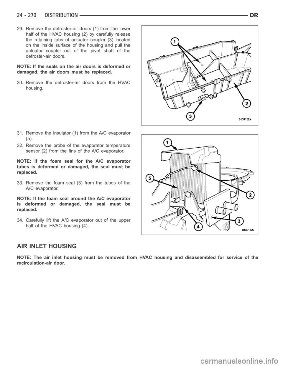
29. Remove the defroster-air doors (1) from the lower
half of the HVAC housing (2) by carefully release
the retaining tabs of actuator coupler (3) located
on the inside surface of the housing and pull the
actuator coupler out of the pivot shaft of the
defroster-air doors.
NOTE: If the seals on the air doors is deformed or
damaged, the air doors must be replaced.
30. Remove the defroster-air doors from the HVAC
housing.
31. Remove the insulator (1) from the A/C evaporator
(5).
32. Remove the probe of the evaporator temperature
sensor (2) from the fins of the A/C evaporator.
NOTE: If the foam seal for the A/C evaporator
tubes is deformed or damaged, the seal must be
replaced.
33. Remove the foam seal (3) from the tubes of the
A/C evaporator.
NOTE: If the foam seal around the A/C evaporator
is deformed or damaged, the seal must be
replaced.
34. Carefully lift the A/C evaporator out of the upper
half of the HVAC housing (4).
AIR INLET HOUSING
NOTE: The air inlet housing must be removed from HVAC housing and disassembled for service of the
recirculation-air door.
Page 5112 of 5267
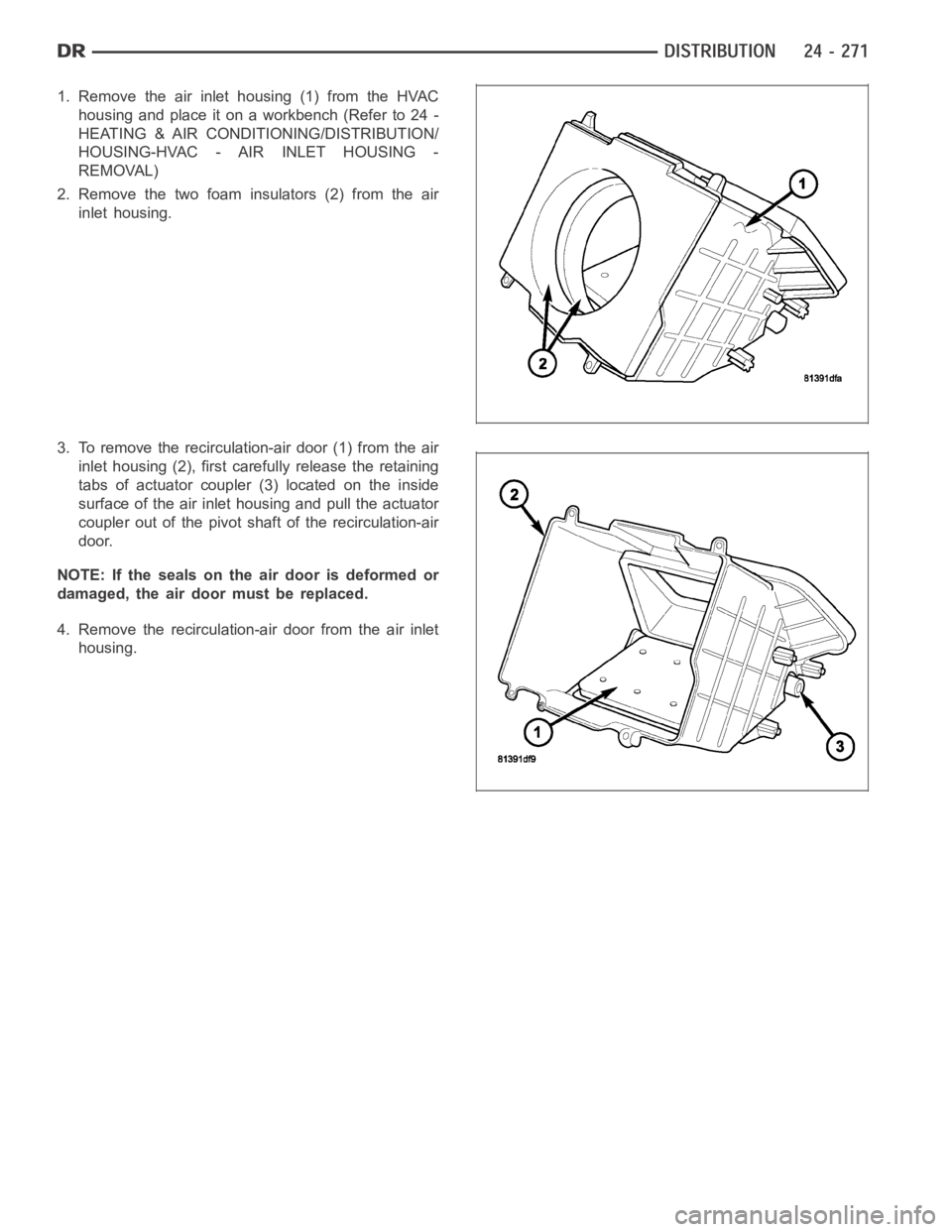
1. Remove the air inlet housing (1) from the HVAC
housing and place it on a workbench (Refer to 24 -
HEATING & AIR CONDITIONING/DISTRIBUTION/
HOUSING-HVAC - AIR INLET HOUSING -
REMOVAL)
2. Remove the two foam insulators (2) from the air
inlet housing.
3. To remove the recirculation-air door (1) from the air
inlet housing (2), first carefully release the retaining
tabs of actuator coupler (3) located on the inside
surface of the air inlet housing and pull the actuator
coupler out of the pivot shaft of the recirculation-air
door.
NOTE: If the seals on the air door is deformed or
damaged, the air door must be replaced.
4. Remove the recirculation-air door from the air inlet
housing.
Page 5113 of 5267
ASSEMBLY
HVAC HOUSING
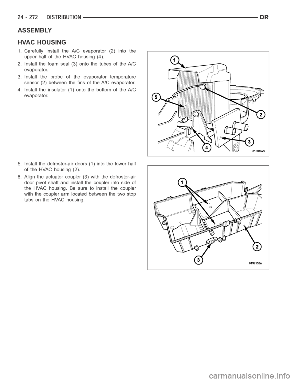
1. Carefully install the A/C evaporator (2) into the
upper half of the HVAC housing (4).
2. Install the foam seal (3) onto the tubes of the A/C
evaporator.
3. Install the probe of the evaporator temperature
sensor (2) between the fins of the A/C evaporator.
4. Install the insulator (1) onto the bottom of the A/C
evaporator.
5. Install the defroster-air doors (1) into the lower half
of the HVAC housing (2).
6. Align the actuator coupler (3) with the defroster-air
door pivot shaft and install the coupler into side of
the HVAC housing. Be sure to install the coupler
with the coupler arm located between the two stop
tabs on the HVAC housing.
Page 5114 of 5267
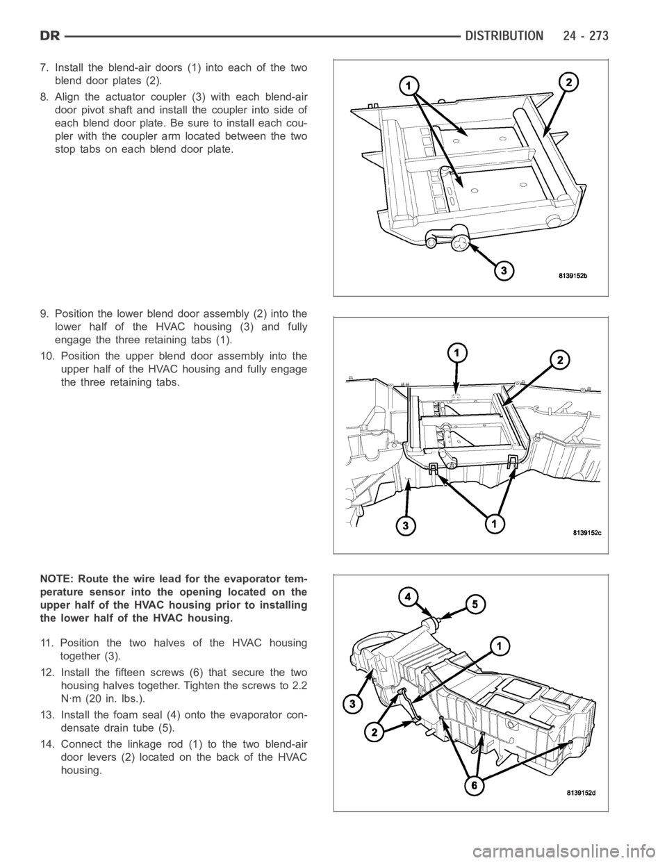
7. Install the blend-air doors (1) into each of the two
blend door plates (2).
8. Align the actuator coupler (3) with each blend-air
door pivot shaft and install the coupler into side of
each blend door plate. Be sure to install each cou-
pler with the coupler arm located between the two
stop tabs on each blend door plate.
9. Position the lower blend door assembly (2) into the
lower half of the HVAC housing (3) and fully
engage the three retaining tabs (1).
10. Position the upper blend door assembly into the
upper half of the HVAC housing and fully engage
the three retaining tabs.
NOTE: Route the wire lead for the evaporator tem-
perature sensor into the opening located on the
upper half of the HVAC housing prior to installing
the lower half of the HVAC housing.
11. Position the two halves of the HVAC housing
together (3).
12. Install the fifteen screws (6) that secure the two
housing halves together. Tighten the screws to 2.2
Nꞏm (20 in. lbs.).
13. Install the foam seal (4) onto the evaporator con-
densate drain tube (5).
14. Connect the linkage rod (1) to the two blend-air
door levers (2) located on the back of the HVAC
housing.
Page 5115 of 5267
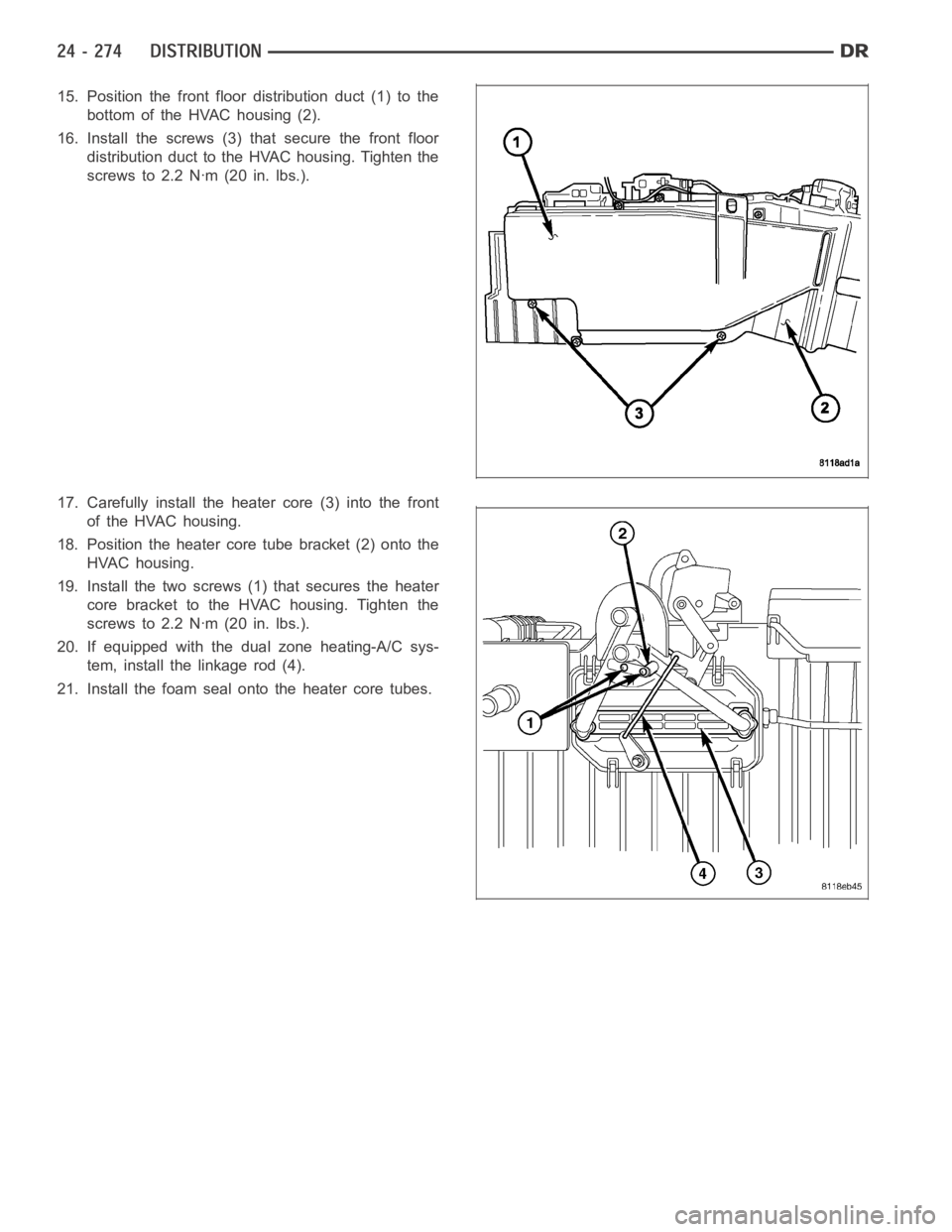
15. Position the front floor distribution duct (1) to the
bottom of the HVAC housing (2).
16. Install the screws (3) that secure the front floor
distribution duct to the HVAC housing. Tighten the
screws to 2.2 Nꞏm (20 in. lbs.).
17. Carefully install the heater core (3) into the front
of the HVAC housing.
18. Position the heater core tube bracket (2) onto the
HVAC housing.
19. Install the two screws (1) that secures the heater
core bracket to the HVAC housing. Tighten the
screws to 2.2 Nꞏm (20 in. lbs.).
20. If equipped with the dual zone heating-A/C sys-
tem, install the linkage rod (4).
21. Install the foam seal onto the heater core tubes.
Page 5116 of 5267
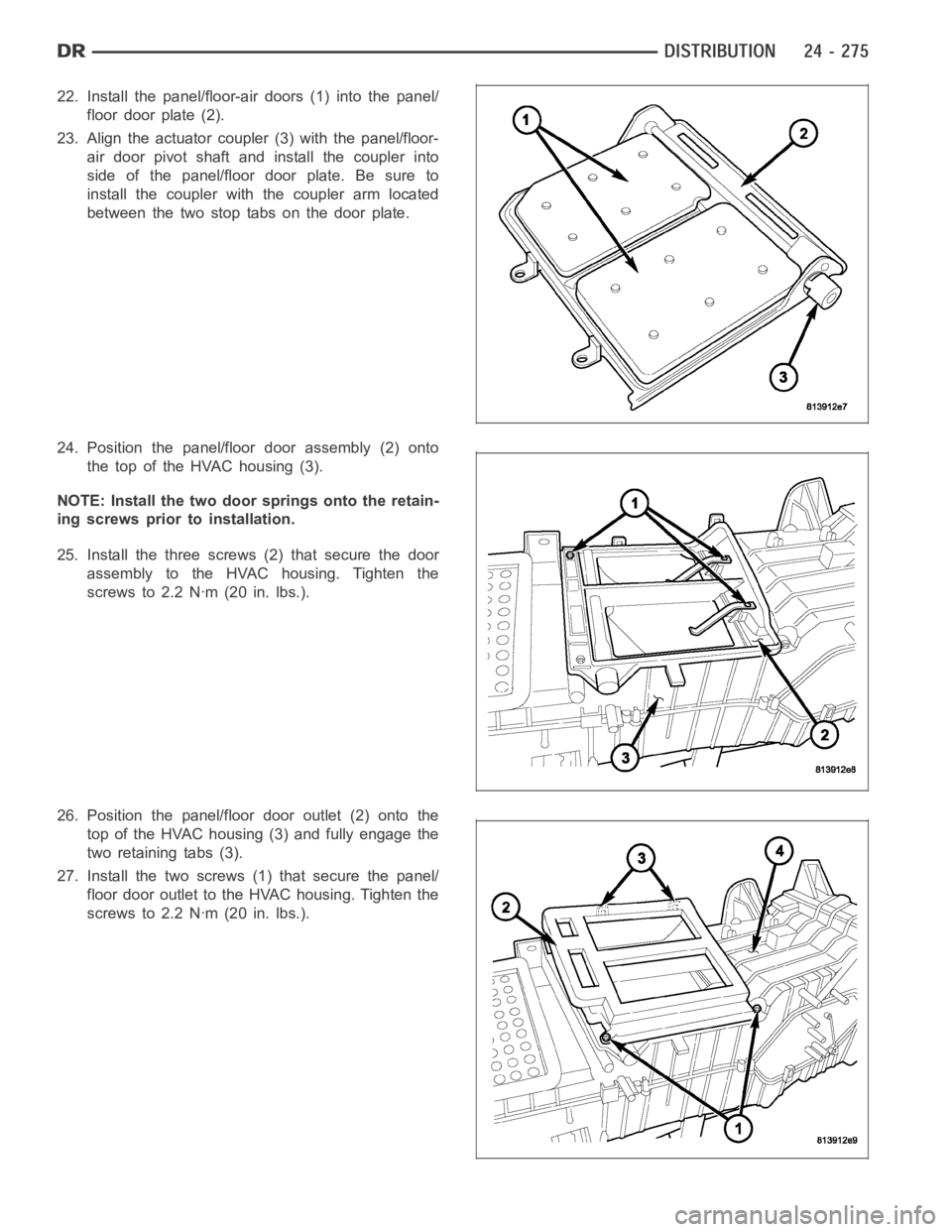
22. Install the panel/floor-air doors (1) into the panel/
floor door plate (2).
23. Align the actuator coupler (3) with the panel/floor-
air door pivot shaft and install the coupler into
side of the panel/floor door plate. Be sure to
install the coupler with the coupler arm located
between the two stop tabs on the door plate.
24. Position the panel/floor door assembly (2) onto
the top of the HVAC housing (3).
NOTE: Install the two door springs onto the retain-
ing screws prior to installation.
25. Install the three screws (2) that secure the door
assembly to the HVAC housing. Tighten the
screws to 2.2 Nꞏm (20 in. lbs.).
26. Position the panel/floor door outlet (2) onto the
top of the HVAC housing (3) and fully engage the
two retaining tabs (3).
27. Install the two screws (1) that secure the panel/
floor door outlet to the HVAC housing. Tighten the
screws to 2.2 Nꞏm (20 in. lbs.).
Page 5117 of 5267
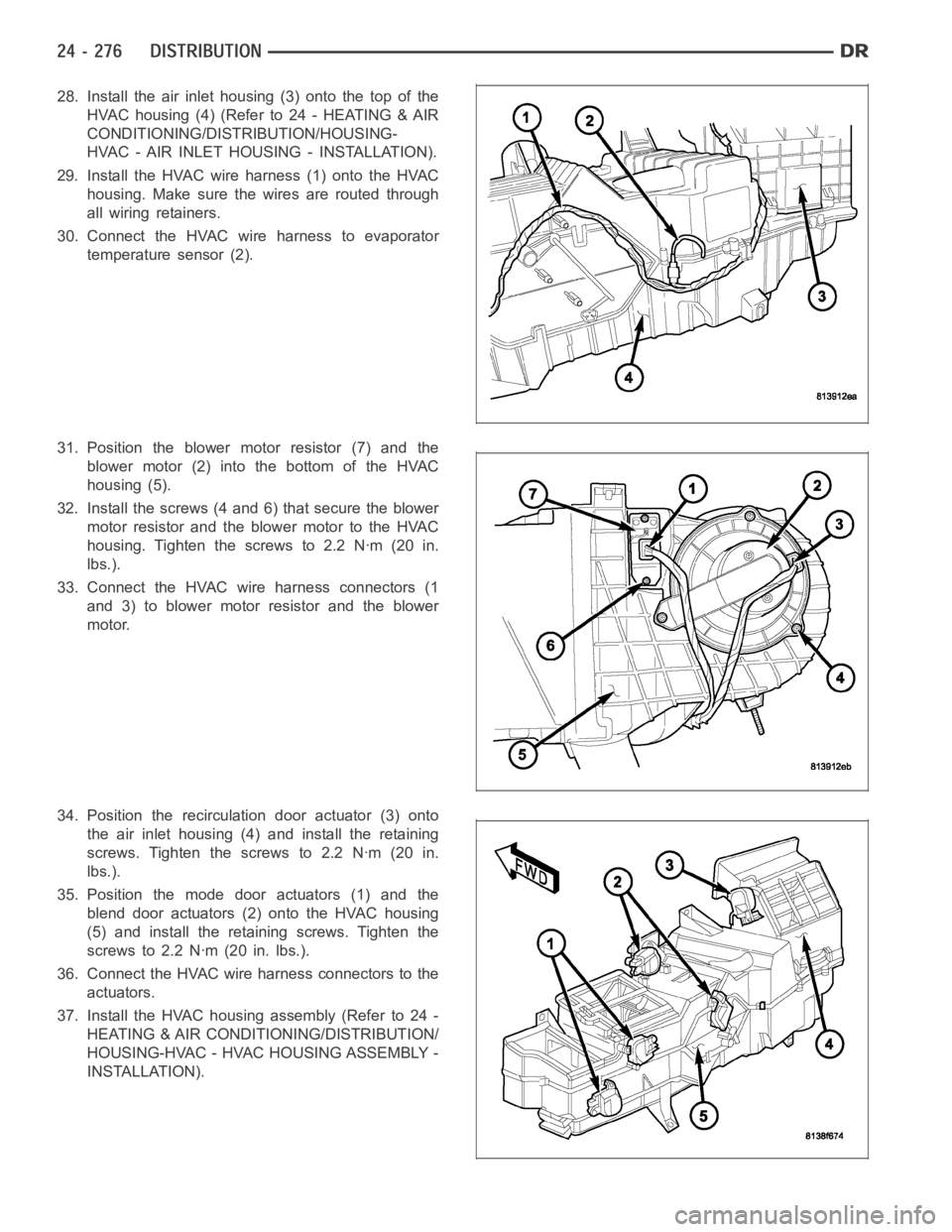
28. Install the air inlet housing (3) onto the top of the
HVAC housing (4) (Refer to 24 - HEATING & AIR
CONDITIONING/DISTRIBUTION/HOUSING-
HVAC - AIR INLET HOUSING - INSTALLATION).
29. Install the HVAC wire harness (1) onto the HVAC
housing. Make sure the wires are routed through
all wiring retainers.
30. Connect the HVAC wire harness to evaporator
temperature sensor (2).
31. Position the blower motor resistor (7) and the
blower motor (2) into the bottom of the HVAC
housing (5).
32. Install the screws (4 and 6) that secure the blower
motor resistor and the blower motor to the HVAC
housing. Tighten the screws to 2.2 Nꞏm (20 in.
lbs.).
33. Connect the HVAC wire harness connectors (1
and 3) to blower motor resistor and the blower
motor.
34. Position the recirculation door actuator (3) onto
the air inlet housing (4) and install the retaining
screws. Tighten the screws to 2.2 Nꞏm (20 in.
lbs.).
35. Position the mode door actuators (1) and the
blend door actuators (2) onto the HVAC housing
(5) and install the retaining screws. Tighten the
screws to 2.2 Nꞏm (20 in. lbs.).
36. Connect the HVAC wire harness connectors to the
actuators.
37. Install the HVAC housing assembly (Refer to 24 -
HEATING & AIR CONDITIONING/DISTRIBUTION/
HOUSING-HVAC - HVAC HOUSING ASSEMBLY -
INSTALLATION).
Page 5118 of 5267
AIR INLET HOUSING
NOTE: The air inlet housing must be removed from HVAC housing and disassembled for service of the
recirculation-air door.
NOTE: If the seals on the air door is deformed or
damaged, the air door must be replaced.
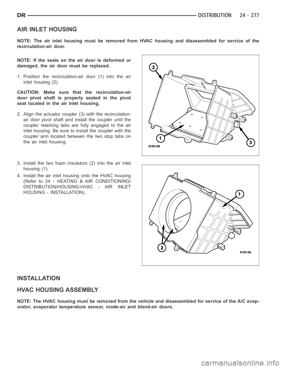
1. Position the recirculation-air door (1) into the air
inlet housing (2).
CAUTION: Make sure that the recirculation-air
door pivot shaft is properly seated in the pivot
seat located in the air inlet housing.
2. Align the actuator coupler (3) with the recirculation-
air door pivot shaft and install the coupler until the
coupler retaining tabs are fully engaged to the air
inlet housing. Be sure to install the coupler with the
coupler arm located between the two stop tabs on
the air inlet housing.
3. Install the two foam insulators (2) into the air inlet
housing (1).
4. Install the air inlet housing onto the HVAC housing
(Refer to 24 - HEATING & AIR CONDITIONING/
DISTRIBUTION/HOUSING-HVAC - AIR INLET
HOUSING - INSTALLATION).
INSTALLATION
HVAC HOUSING ASSEMBLY
NOTE: The HVAC housing must be removedfrom the vehicle and disassembled for service of the A/C evap-
orator, evaporator temperature sensor, mode-air and blend-air doors.
Page 5119 of 5267
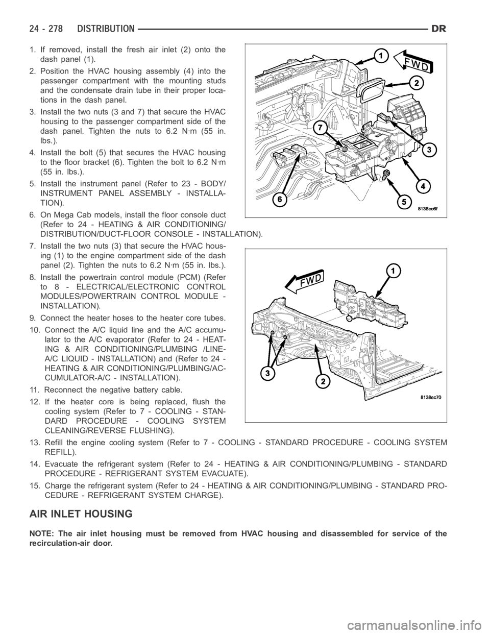
1. If removed, install the fresh air inlet (2) onto the
dash panel (1).
2. Position the HVAC housing assembly (4) into the
passenger compartment with the mounting studs
and the condensate drain tube in their proper loca-
tions in the dash panel.
3. Install the two nuts (3 and 7) that secure the HVAC
housing to the passenger compartment side of the
dash panel. Tighten the nuts to 6.2 Nꞏm (55 in.
lbs.).
4. Install the bolt (5) that secures the HVAC housing
to the floor bracket (6). Tighten the bolt to 6.2 Nꞏm
(55 in. lbs.).
5. Install the instrument panel (Refer to 23 - BODY/
INSTRUMENT PANEL ASSEMBLY - INSTALLA-
TION).
6. On Mega Cab models, install the floor console duct
(Refer to 24 - HEATING & AIR CONDITIONING/
DISTRIBUTION/DUCT-FLOOR CONSOLE - INSTALLATION).
7. Install the two nuts (3) that secure the HVAC hous-
ing (1) to the engine compartment side of the dash
panel (2). Tighten the nuts to 6.2 Nꞏm (55 in. lbs.).
8. Install the powertrain control module (PCM) (Refer
to 8 - ELECTRICAL/ELECTRONIC CONTROL
MODULES/POWERTRAIN CONTROL MODULE -
INSTALLATION).
9. Connect the heater hoses to the heater core tubes.
10. Connect the A/C liquid line and the A/C accumu-
lator to the A/C evaporator (Refer to 24 - HEAT-
ING & AIR CONDITIONING/PLUMBING /LINE-
A/C LIQUID - INSTALLATION) and (Refer to 24 -
HEATING & AIR CONDITIONING/PLUMBING/AC-
CUMULATOR-A/C - INSTALLATION).
11. Reconnect the negative battery cable.
12. If the heater core is being replaced, flush the
coolingsystem(Referto7-COOLING-STAN-
DARD PROCEDURE - COOLING SYSTEM
CLEANING/REVERSE FLUSHING).
13. Refill the engine cooling system (Refer to 7 - COOLING - STANDARD PROCEDURE - COOLING SYSTEM
REFILL).
14. Evacuate the refrigerant system (Refer to 24 - HEATING & AIR CONDITIONING/PLUMBING - STANDARD
PROCEDURE - REFRIGERANT SYSTEM EVACUATE).
15. Charge the refrigerant system (Refer to 24 - HEATING & AIR CONDITIONING/PLUMBING - STANDARD PRO-
CEDURE - REFRIGERANT SYSTEM CHARGE).
AIR INLET HOUSING
NOTE: The air inlet housing must be removed from HVAC housing and disassembled for service of the
recirculation-air door.
Page 5120 of 5267
NOTE: If the foam seal on the air inlet housing is
deformed or damaged, it must be replaced.
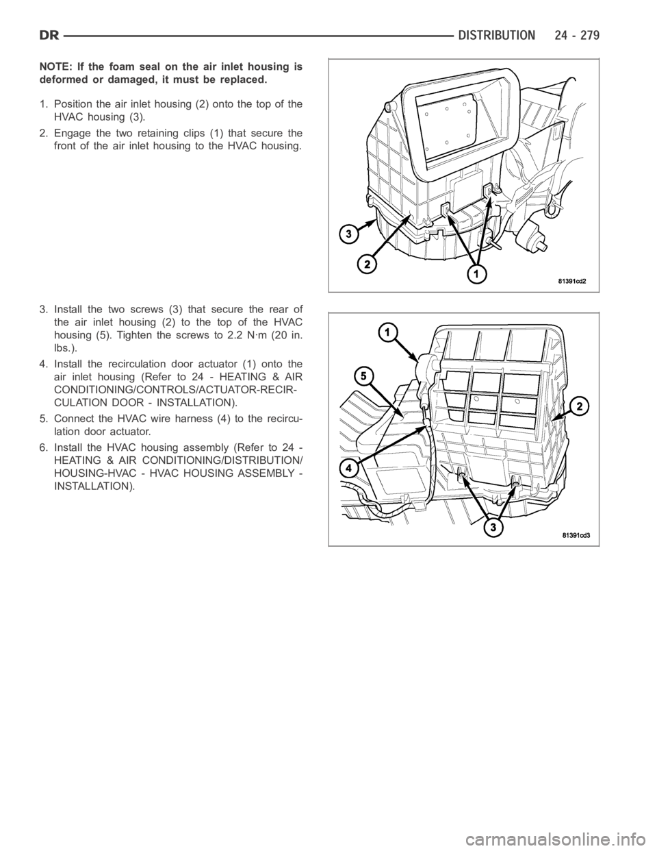
1. Position the air inlet housing (2) onto the top of the
HVAC housing (3).
2. Engage the two retaining clips (1) that secure the
front of the air inlet housing to the HVAC housing.
3. Install the two screws (3) that secure the rear of
the air inlet housing (2) to the top of the HVAC
housing (5). Tighten the screws to 2.2 Nꞏm (20 in.
lbs.).
4. Install the recirculation door actuator (1) onto the
air inlet housing (Refer to 24 - HEATING & AIR
CONDITIONING/CONTROLS/ACTUATOR-RECIR-
CULATION DOOR - INSTALLATION).
5. Connect the HVAC wire harness (4) to the recircu-
lation door actuator.
6. Install the HVAC housing assembly (Refer to 24 -
HEATING & AIR CONDITIONING/DISTRIBUTION/
HOUSING-HVAC - HVAC HOUSING ASSEMBLY -
INSTALLATION).