DODGE RAM SRT-10 2006 Service Repair Manual
Manufacturer: DODGE, Model Year: 2006, Model line: RAM SRT-10, Model: DODGE RAM SRT-10 2006Pages: 5267, PDF Size: 68.7 MB
Page 5091 of 5267
INSTALLATION
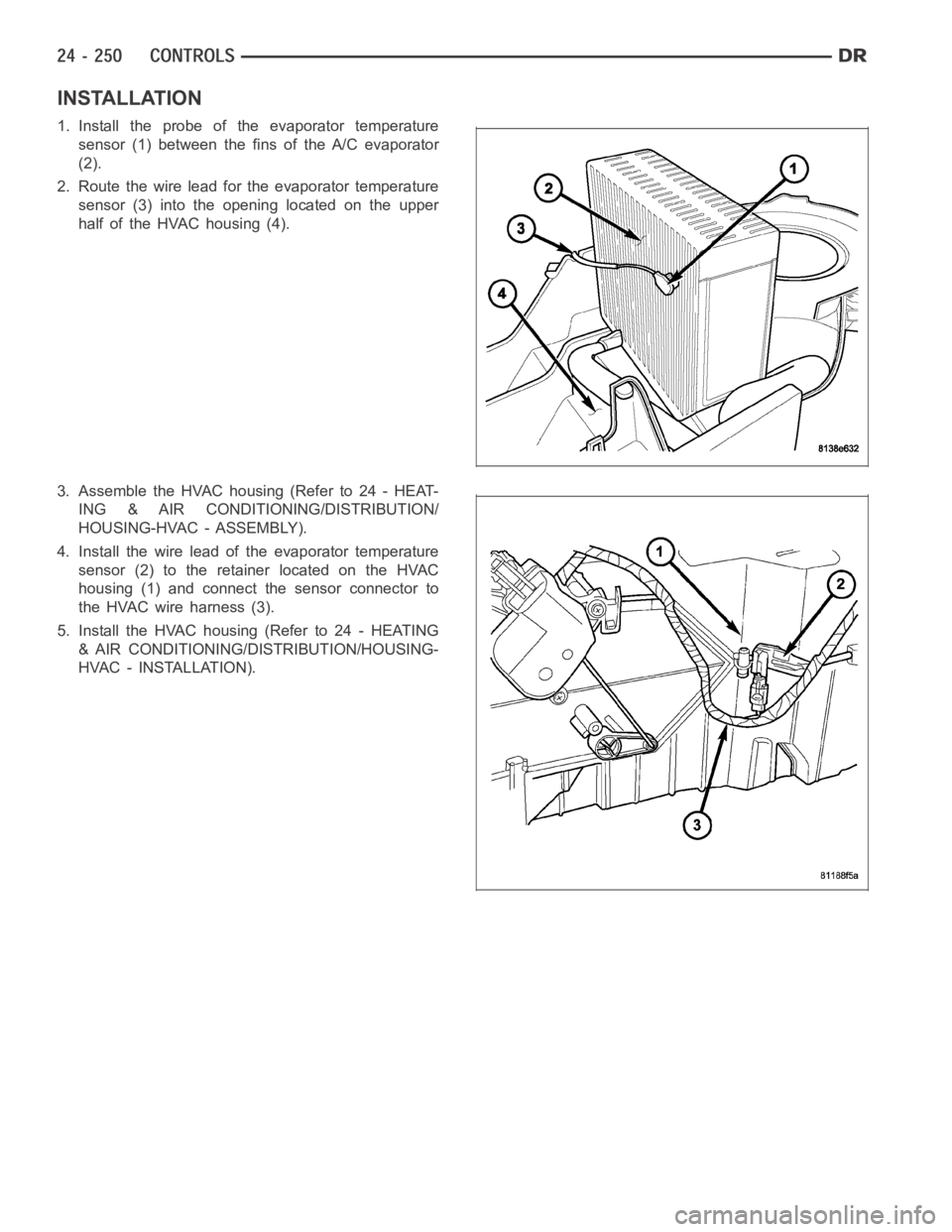
1. Install the probe of the evaporator temperature
sensor (1) between the fins of the A/C evaporator
(2).
2. Route the wire lead for the evaporator temperature
sensor (3) into the opening located on the upper
half of the HVAC housing (4).
3. Assemble the HVAC housing (Refer to 24 - HEAT-
ING & AIR CONDITIONING/DISTRIBUTION/
HOUSING-HVAC - ASSEMBLY).
4. Install the wire lead of the evaporator temperature
sensor (2) to the retainer located on the HVAC
housing (1) and connect the sensor connector to
theHVACwireharness(3).
5. Install the HVAC housing (Refer to 24 - HEATING
& AIR CONDITIONING/DISTRIBUTION/HOUSING-
HVAC - INSTALLATION).
Page 5092 of 5267
TRANSDUCER-A/C PRESSURE
DESCRIPTION
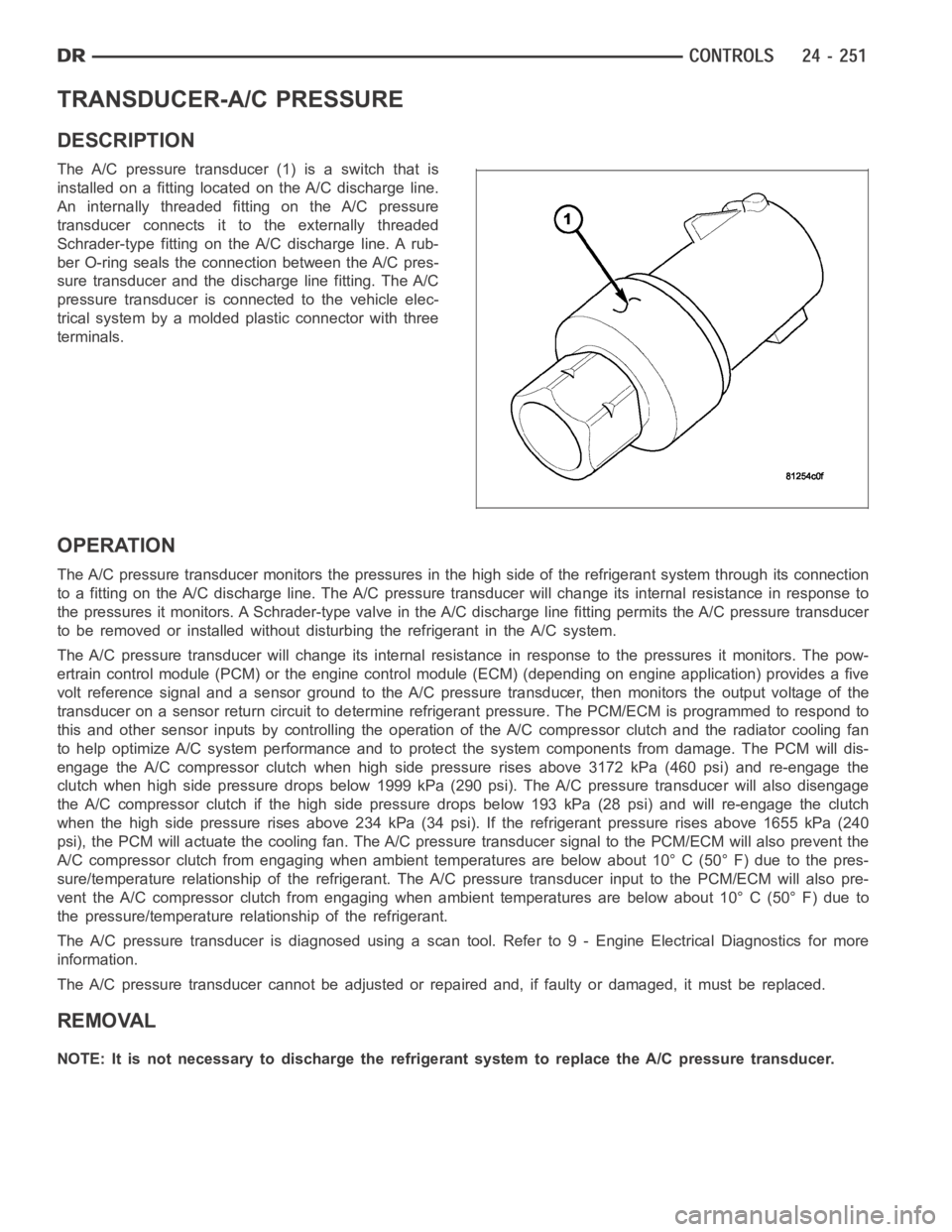
The A/C pressure transducer (1) is a switch that is
installed on a fitting located on the A/C discharge line.
An internally threaded fitting on the A/C pressure
transducer connects it to the externally threaded
Schrader-type fitting on the A/C discharge line. A rub-
ber O-ring seals the connection between the A/C pres-
sure transducer and the discharge line fitting. The A/C
pressure transducer is connected to the vehicle elec-
trical system by a molded plastic connector with three
terminals.
OPERATION
The A/C pressure transducer monitors the pressures in the high side of the refrigerant system through its connection
to a fitting on the A/C discharge line. The A/C pressure transducer will change its internal resistance in response to
the pressures it monitors. A Schrader-type valve in the A/C discharge linefitting permits the A/C pressure transducer
to be removed or installed without disturbing the refrigerant in the A/C system.
The A/C pressure transducer will change its internal resistance in response to the pressures it monitors. The pow-
ertrain control module (PCM) or the engine control module (ECM) (depending on engine application) provides a five
volt reference signal and a sensor ground to the A/C pressure transducer, then monitors the output voltage of the
transducer on a sensor return circuit to determine refrigerant pressure.The PCM/ECM is programmed to respond to
this and other sensor inputs by controlling the operation of the A/C compressor clutch and the radiator cooling fan
to help optimize A/C system performance and to protect the system components from damage. The PCM will dis-
engagetheA/Ccompressorclutchwhenhighsidepressurerisesabove3172kPa (460 psi) and re-engage the
clutch when high side pressure drops below 1999 kPa (290 psi). The A/C pressure transducer will also disengage
the A/C compressor clutch if the high side pressure drops below 193 kPa (28 psi) and will re-engage the clutch
when the high side pressure rises above 234 kPa (34 psi). If the refrigerantpressure rises above 1655 kPa (240
psi), the PCM will actuate the cooling fan. The A/C pressure transducer signal to the PCM/ECM will also prevent the
A/C compressor clutch from engaging when ambient temperatures are below about 10° C (50° F) due to the pres-
sure/temperature relationship of the refrigerant. The A/C pressure transducer input to the PCM/ECM will also pre-
vent the A/C compressor clutch from engaging when ambient temperatures are below about 10° C (50° F) due to
the pressure/temperature relationship of the refrigerant.
The A/C pressure transducer is diagnosed using a scan tool. Refer to 9 - Engine Electrical Diagnostics for more
information.
The A/C pressure transducer cannot be adjusted or repaired and, if faulty or damaged, it must be replaced.
REMOVAL
NOTE: It is not necessary to discharge the refrigerant system to replace the A/C pressure transducer.
Page 5093 of 5267
1. Disconnect and isolate the negative battery cable.
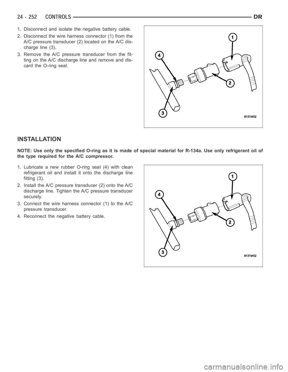
2. Disconnect the wire harness connector (1) from the
A/C pressure transducer (2) located on the A/C dis-
charge line (3).
3. Remove the A/C pressure transducer from the fit-
ting on the A/C discharge line and remove and dis-
card the O-ring seal.
INSTALLATION
NOTE:UseonlythespecifiedO-ringasitismadeofspecialmaterialforR-134a. Use only refrigerant oil of
the type required for the A/C compressor.
1. Lubricate a new rubber O-ring seal (4) with clean
refrigerant oil and install it onto the discharge line
fitting (3).
2. Install the A/C pressure transducer (2) onto the A/C
discharge line. Tighten the A/C pressure transducer
securely.
3. Connect the wire harness connector (1) to the A/C
pressure transducer.
4. Reconnect the negative battery cable.
Page 5094 of 5267
page page
DUCT-DEFROSTER
REMOVAL ................................... 254
INSTALLATION .............................. 255
DUCT-FLOOR CONSOLE
REMOVAL ................................... 256
INSTALLATION .............................. 256
DUCT-FLOOR DISTRIBUTION
REMOVAL ................................... 257
INSTALLATION .............................. 257
DUCT-INSTRUMENT PANEL
REMOVAL ................................... 258
INSTALLATION .............................. 259
DUCT-INSTRUMENT PANEL DEMISTER
REMOVAL ................................... 260
INSTALLATION .............................. 261
HOUSING-HVAC
DESCRIPTION ............................... 262
REMOVAL
HVAC HOUSING ASSEMBLY . . .............. 263AIR INLET HOUSING ....................... 264
DISASSEMBLY
HVAC HOUSING ........................... 265
AIR INLET HOUSING ....................... 270
ASSEMBLY
HVAC HOUSING ........................... 272
AIR INLET HOUSING ....................... 277
INSTALLATION
HVAC HOUSING ASSEMBLY ................ 277
AIR INLET HOUSING ....................... 278
MOTOR-BLOWER
DESCRIPTION ............................... 280
OPERATION ................................. 280
DIAGNOSIS AND TESTING
BLOWER MOTOR ......................... 280
REMOVAL ................................... 282
INSTALLATION .............................. 282
OUTLETS-AIR
DESCRIPTION ............................... 283
Page 5095 of 5267
DUCT-DEFROSTER
REMOVAL
WARNING: On vehicles equipped with airbags, disable the airbag system before attempting any steering
wheel, steering column, or instrument panel component diagnosis or service. Disconnect and isolate the
battery negative (ground) cable, then wait two minutes for the airbag system capacitor to discharge before
performing further diagnosis or service. This is the only sure way to disable the airbag system. Failure to
take the proper precautions could result in accidental airbag deploymentand possible personal injury or
death.
NOTE: Take the proper precautions to protect the instrument panel from cosmetic damage.
1. Remove the instrument panel and place it on a workbench (Refer to 23 - BODY/INSTRUMENT PANEL/INSTRU-
MENT PANEL ASSEMBLY - REMOVAL).
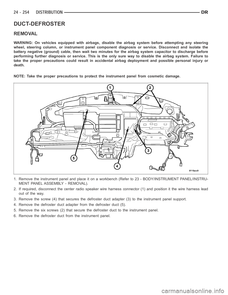
2. If required, disconnect the center radio speaker wire harness connector (1) and position it the wire harness lead
out of the way.
3. Remove the screw (4) that secures the defroster duct adapter (3) to the instrument panel support.
4. Remove the defroster duct adapter from the defroster duct (5).
5. Remove the six screws (2) that secure the defroster duct to the instrument panel.
6. Remove the defroster duct from the instrument panel.
Page 5096 of 5267
INSTALLATION
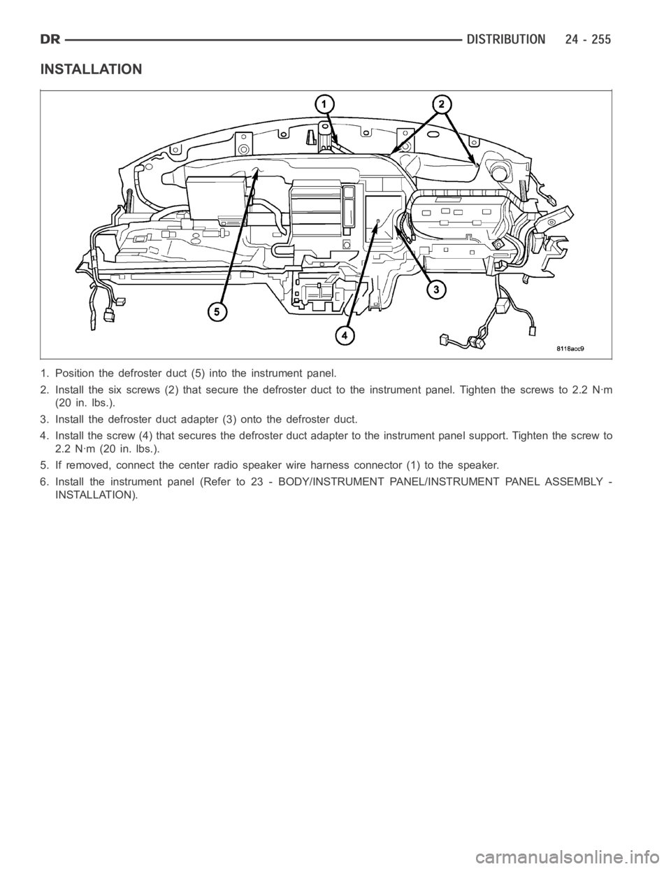
1. Position the defroster duct (5) into the instrument panel.
2. Install the six screws (2) that secure the defroster duct to the instrument panel. Tighten the screws to 2.2 Nꞏm
(20 in. lbs.).
3. Install the defroster duct adapter (3) onto the defroster duct.
4. Install the screw (4) that secures the defroster duct adapter to the instrument panel support. Tighten the screw to
2.2 Nꞏm (20 in. lbs.).
5. If removed, connect the center radiospeaker wire harness connector (1)to the speaker.
6. Install the instrument panel (Refer to 23 - BODY/INSTRUMENT PANEL/INSTRUMENT PANEL ASSEMBLY -
INSTALLATION).
Page 5097 of 5267
DUCT-FLOOR CONSOLE
REMOVAL
NOTE: Illustration shown with seat cushions
removed from view for clarity.
1. Removethefloorconsole(Referto23-BODY/IN-
TERIOR/FLOOR CONSOLE - REMOVAL).
2. Slide the floor console duct (1) rearward and first
disconnect it from the floor distribution duct (3)
located on the bottom of the HVAC housing (4), then disconnect the floor duct from the rear duct (33) located
below the center seat.
3. If required, remove the rear duct from the center seat support.
INSTALLATION
NOTE: Illustration shown with seat cushions
removed from view for clarity.
1. If removed, install the rear duct (2) to the bottom of
the center seat support. Make sure the duct is fully
engaged to the rear outlets.
2. Install the floor console duct (1) onto the rear duct
and then slide it forward and connect it to the floor distribution duct (3) located at the bottom of the HVAC hous-
ing (4). Make sure all ducts are fully to each other.
3. Install the floor console (Refer to 23 - BODY/INTERIOR/FLOOR CONSOLE - INSTALLATION).
Page 5098 of 5267
DUCT-FLOOR DISTRIBUTION
REMOVAL
WARNING: On vehicles equipped with airbags, disable the airbag system before attempting any steering
wheel, steering column, or instrument panel component diagnosis or service. Disconnect and isolate the
battery negative (ground) cable, then wait two minutes for the airbag system capacitor to discharge before
performing further diagnosis or service. This is the only sure way to disable the airbag system. Failure to
take the proper precautions could result in an accidental airbag deployment and possible personal injury or
death.
NOTE: Regular Cab model shown. Other models
similar.
1. Remove the HVAC housing from the vehicle (Refer
to 24 - HEATING & AIR CONDITIONING/DISTRI-
BUTION/HOUSING-HVAC - REMOVAL).
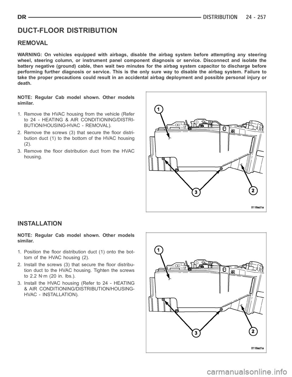
2. Remove the screws (3) that secure the floor distri-
bution duct (1) to the bottom of the HVAC housing
(2).
3. Remove the floor distribution duct from the HVAC
housing.
INSTALLATION
NOTE: Regular Cab model shown. Other models
similar.
1. Position the floor distribution duct (1) onto the bot-
tom of the HVAC housing (2).
2. Install the screws (3) that secure the floor distribu-
tion duct to the HVAC housing. Tighten the screws
to 2.2 Nꞏm (20 in. lbs.).
3. Install the HVAC housing (Refer to 24 - HEATING
& AIR CONDITIONING/DISTRIBUTION/HOUSING-
HVAC - INSTALLATION).
Page 5099 of 5267
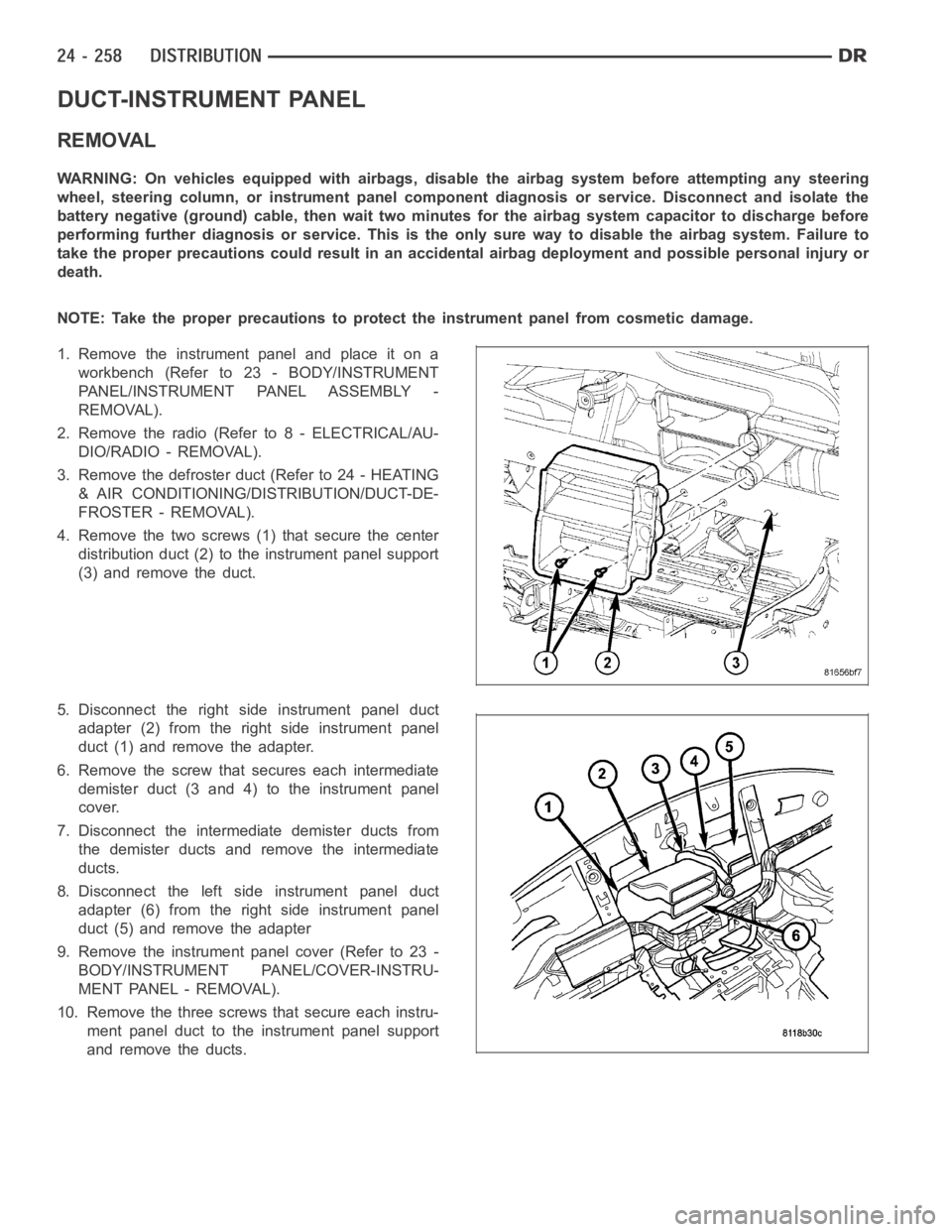
DUCT-INSTRUMENT PANEL
REMOVAL
WARNING: On vehicles equipped with airbags, disable the airbag system before attempting any steering
wheel, steering column, or instrument panel component diagnosis or service. Disconnect and isolate the
battery negative (ground) cable, then wait two minutes for the airbag system capacitor to discharge before
performing further diagnosis or service. This is the only sure way to disable the airbag system. Failure to
take the proper precautions could result in an accidental airbag deployment and possible personal injury or
death.
NOTE: Take the proper precautions to protect the instrument panel from cosmetic damage.
1. Remove the instrument panel and place it on a
workbench (Refer to 23 - BODY/INSTRUMENT
PANEL/INSTRUMENT PANEL ASSEMBLY -
REMOVAL).
2. Remove the radio (Refer to 8 - ELECTRICAL/AU-
DIO/RADIO - REMOVAL).
3. Remove the defroster duct (Refer to 24 - HEATING
& AIR CONDITIONING/DISTRIBUTION/DUCT-DE-
FROSTER - REMOVAL).
4. Remove the two screws (1) that secure the center
distribution duct (2) to the instrument panel support
(3) and remove the duct.
5. Disconnect the right side instrument panel duct
adapter (2) from the right side instrument panel
duct (1) and remove the adapter.
6. Remove the screw that secures each intermediate
demister duct (3 and 4) to the instrument panel
cover.
7. Disconnect the intermediate demister ducts from
the demister ducts and remove the intermediate
ducts.
8. Disconnect the left side instrument panel duct
adapter (6) from the right side instrument panel
duct (5) and remove the adapter
9. Remove the instrument panel cover (Refer to 23 -
BODY/INSTRUMENT PANEL/COVER-INSTRU-
MENT PANEL - REMOVAL).
10. Remove the three screws that secure each instru-
ment panel duct to the instrument panel support
and remove the ducts.
Page 5100 of 5267
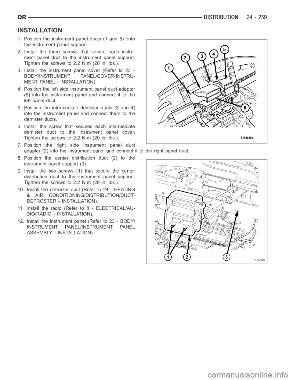
INSTALLATION
1. Position the instrument panel ducts (1 and 5) onto
the instrument panel support.
2. Install the three screws that secure each instru-
ment panel duct to the instrument panel support.
Tighten the screws to 2.2 Nꞏm (20 in. lbs.).
3. Install the instrument panel cover (Refer to 23 -
BODY/INSTRUMENT PANEL/COVER-INSTRU-
MENT PANEL - INSTALLATION).
4. Position the left side instrument panel duct adapter
(6) into the instrument panel and connect it to the
left panel duct.
5. Position the intermediate demister ducts (3 and 4)
into the instrument panel and connect them to the
demister ducts.
6. Install the screw that secures each intermediate
demister duct to the instrument panel cover.
Tighten the screws to 2.2 Nꞏm (20 in. lbs.).
7. Position the right side instrument panel duct
adapter (2) into the instrument panel and connect it to the right panel duct.
8. Position the center distribution duct (2) to the
instrument panel support (3).
9. Install the two screws (1) that secure the center
distribution duct to the instrument panel support.
Tighten the screws to 2.2 Nꞏm (20 in. lbs.).
10. Install the defroster duct (Refer to 24 - HEATING
& AIR CONDITIONING/DISTRIBUTION/DUCT-
DEFROSTER - INSTALLATION).
11. Install the radio (Refer to 8 - ELECTRICAL/AU-
DIO/RADIO - INSTALLATION).
12. Install the instrument panel (Refer to 23 - BODY/
INSTRUMENT PANEL/INSTRUMENT PANEL
ASSEMBLY - INSTALLATION).