display DODGE RAM SRT-10 2006 Service Manual PDF
[x] Cancel search | Manufacturer: DODGE, Model Year: 2006, Model line: RAM SRT-10, Model: DODGE RAM SRT-10 2006Pages: 5267, PDF Size: 68.7 MB
Page 3660 of 5267
When Monitored:
Continuously with the ignition on and engine running.
Set Condition:
The Transmission governor pressure set point is above a threshold while inparkortheP/Nswitchisindrive
during an engine start.
Possible Causes
TRS CONNECTOR DAMAGE OR CORROSION
ECM CONNECTOR DAMAGE OR CORROSION
(T41) P/N POSITION SWITCH SENSE CIRCUIT OPEN
(T41) P/N POSITION SWITCH SENSE CIRCUIT SHORT TO GROUND
(T41) P/N POSITION SWITCH SENSE CIRCUIT SHORT TO ANOTHER CIRCUIT
TRANSMISSION RANGE SENSOR
ENGINE CONTROL MODULE
Always perform the Pre-Diagnostic Troubleshooting procedure before proceeding. (Refer to 21 - TRANSMIS-
SION/TRANSAXLE/AUTOMATIC - 48RE - STANDARD PROCEDURE)
Diagnostic Test
1.CHECK IF THE SCAN TOOL DISPLAYS P/N AND D/R IN THE CORRECT POSITION
Ignition on, engine not running.
With the scan tool, monitor the PNP switch input state.
Move the gear selector through all gear positions Park to 1st and back to Park.
Did the scan tool display P/N and D/R in the correct gear positions?
Ye s>>
Go To 8
No>>
Go To 2
2.CHECK THE TRS CONNECTOR FOR DAMAGE OR CORROSION
Turn the ignition off to the lock position.
Disconnect the Transmission Range Sensor harness connector.
Inspect the Transmission Range Sensor harness wiring and connector for damage, pushed out pins, or corrosion,
etc.
Were there any problems found?
Ye s>>
Repair as necessary.
Perform RE TRANSMISSION VERIFICATION TEST VER - 1 (DIESEL). (Refer to 21 - TRANSMISSION/
TRANSAXLE/AUTOMATIC - 48RE - STANDARD PROCEDURE)
No>>
Go To 3
3.CHECK THE ECM CONNECTOR FOR DAMAGE OR CORROSION
Disconnect the ECM C2 harness connector.
Inspect the ECM wiring and connector for damage, pushed out pins, or corrosion, etc.
Were there any problems found?
Ye s>>
Repair as necessary.
Perform RE TRANSMISSION VERIFICATION TEST VER - 1 (DIESEL). (Refer to 21 - TRANSMISSION/
TRANSAXLE/AUTOMATIC - 48RE - STANDARD PROCEDURE)
No>>
Go To 4
Page 3662 of 5267
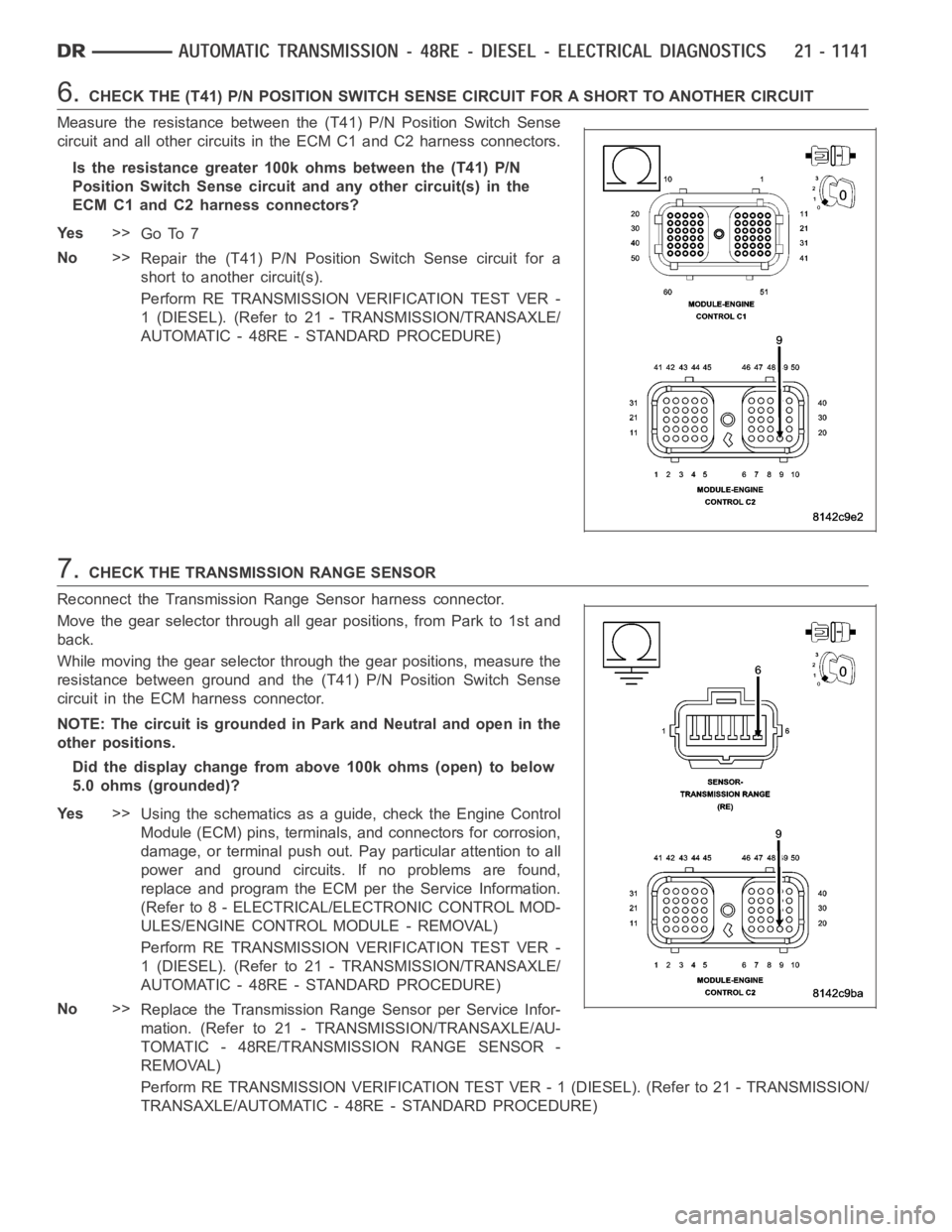
6.CHECK THE (T41) P/N POSITION SWITCH SENSE CIRCUIT FOR A SHORT TO ANOTHER CIRCUIT
Measure the resistance between the (T41) P/N Position Switch Sense
circuit and all other circuits in the ECM C1 and C2 harness connectors.
Is the resistance greater 100k ohms between the (T41) P/N
Position Switch Sense circuitand any other circuit(s) in the
ECM C1 and C2 harness connectors?
Ye s>>
Go To 7
No>>
Repair the (T41) P/N Position Switch Sense circuit for a
short to another circuit(s).
Perform RE TRANSMISSION VERIFICATION TEST VER -
1 (DIESEL). (Refer to 21 - TRANSMISSION/TRANSAXLE/
AUTOMATIC - 48RE - STANDARD PROCEDURE)
7.CHECK THE TRANSMISSION RANGE SENSOR
Reconnect the Transmission Range Sensor harness connector.
Move the gear selector through all gear positions, from Park to 1st and
back.
While moving the gear selector through the gear positions, measure the
resistance between ground and the (T41) P/N Position Switch Sense
circuit in the ECM harness connector.
NOTE: The circuit is grounded in Park and Neutral and open in the
other positions.
Did the display change from above 100k ohms (open) to below
5.0 ohms (grounded)?
Ye s>>
Using the schematics as a guide, check the Engine Control
Module (ECM) pins, terminals, and connectors for corrosion,
damage, or terminal push out. Pay particular attention to all
power and ground circuits. If no problems are found,
replace and program the ECM per the Service Information.
(Refer to 8 - ELECTRICAL/ELECTRONIC CONTROL MOD-
ULES/ENGINE CONTROL MODULE - REMOVAL)
Perform RE TRANSMISSION VERIFICATION TEST VER -
1 (DIESEL). (Refer to 21 - TRANSMISSION/TRANSAXLE/
AUTOMATIC - 48RE - STANDARD PROCEDURE)
No>>
Replace the Transmission Range Sensor per Service Infor-
mation. (Refer to 21 - TRANSMISSION/TRANSAXLE/AU-
TOMATIC - 48RE/TRANSMISSION RANGE SENSOR -
REMOVAL)
Perform RE TRANSMISSION VERIFICATION TEST VER - 1 (DIESEL). (Refer to 21 - TRANSMISSION/
TRANSAXLE/AUTOMATIC - 48RE - STANDARD PROCEDURE)
Page 3711 of 5267
3.CHECK IF THE DTC IS CURRENT
With the scan tool, read Engine DTCs.
Record the Freeze Frame data for the reported DTC.
With the scan tool, erase DTCs.
Turn the ignition off to the lock position.
Using the Freeze Frame data recorded earlier, try to duplicate the conditions in which the DTC originally set.
NOTE: It may be necessary to road test the vehicle to duplicate the originalset conditions.
With the scan tool, read Engine DTCs.
Did the DTC reset?
Ye s>>
Go To 4
No>>
Go To 14
4.VERIFY THE TOW/ HAUL OVERDRIVE FEATURE
NOTE: The transmission fluid temperature must be above 0.0° C (32° F) before proceeding.
With the scan tool, build a custom display using: Engine RPM, Output Shaft Speed, TCC Solenoid, O/D Solenoid
and TPS.
NOTE: This display will monitor the operation of the components.
Start the engine, turn off Overdrive or Tow Haul and test drive the vehicle.
Attain a steady speed of 88.5 Kmh or 55 mph with a minimum of 1.15 volts throttle opening for 20 seconds.
NOTE: Check the Shift pattern as the vehicle upshifts to speeds of 88.5 Kmh or55mph.
Is the Engine RPM within 60 RPM of the Output Shaft Speed RPM?
Ye s>>
Go To 10
No>>
Go To 5
5.CHECK IF THE OUTPUT SPEED IS GREATER THAN ENGINE RPM
In the previous test, is the Output Shaft Speed greater than Engine RPM?
Ye s>>
Go To 6
No>>
Go To 10
6.CALCULATE EXPECTED ENGINE RPM
With the scan tool, build a custom display using: Engine RPM, Output Shaft Speed, TCC Solenoid, O/D Solenoid
and TPS.
NOTE: This display will monitor the operation of the components.
Start the engine, turn off Overdrive or Tow Haul and test drive the vehicle.
Attain a steady speed of 88.5 Kmh or 55 mph with a minimum of 1.15 volts throttle opening for 20 seconds.
With the scan tool, verify the 3-4 Solenoid (O/D) Solenoid is on and the TCC solenoid is locked
NOTE: Use this formula, Output Shaft Speed x 0.69 = expected Engine RPM.
Did the Engine RPM drop to 0.69 of the Output Shaft Speed RPM?
Ye s>>
Go To 10
No>>
Go To 7
Page 3963 of 5267
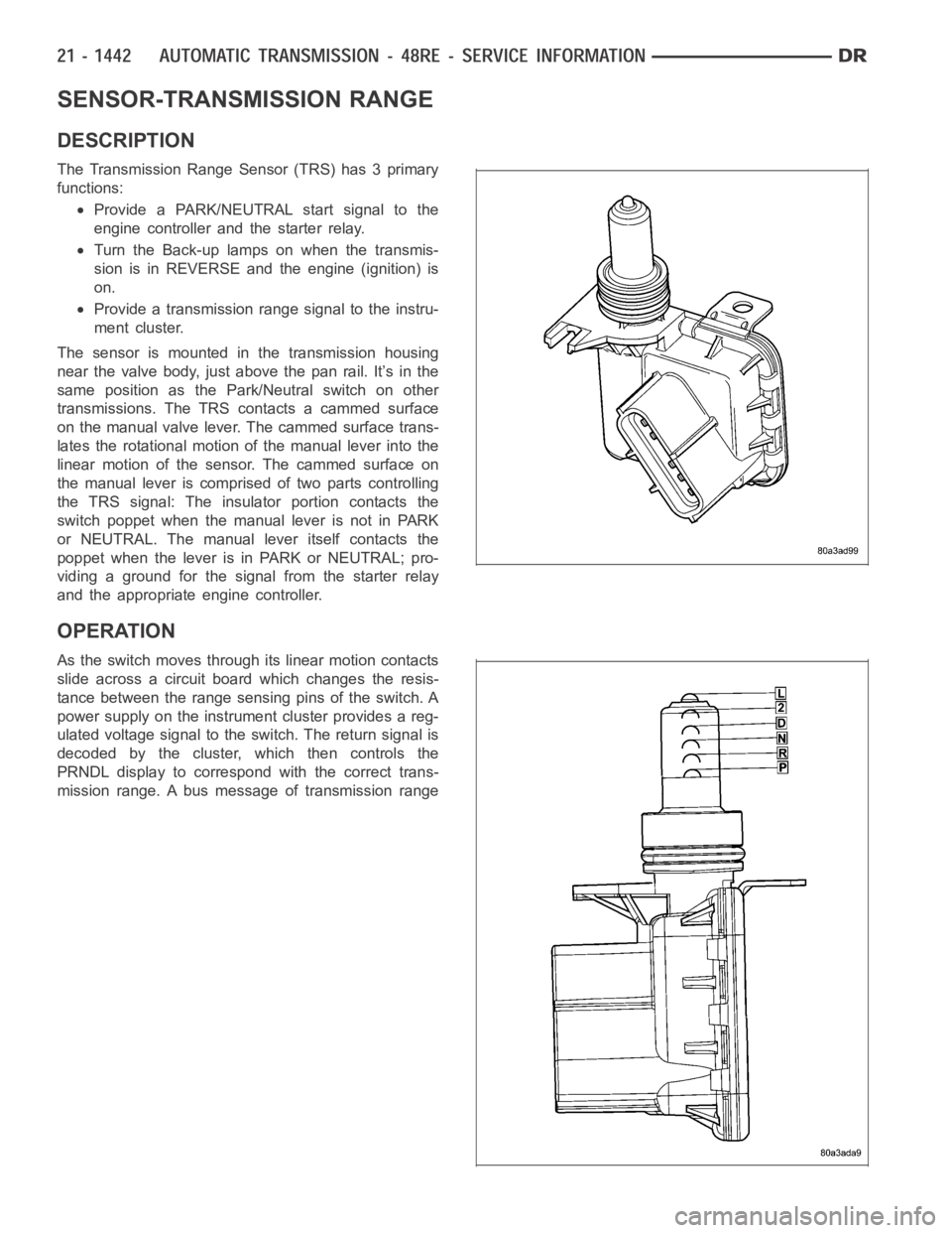
SENSOR-TRANSMISSION RANGE
DESCRIPTION
The Transmission Range Sensor (TRS) has 3 primary
functions:
Provide a PARK/NEUTRAL start signal to the
engine controller and the starter relay.
Turn the Back-up lamps on when the transmis-
sion is in REVERSE and the engine (ignition) is
on.
Provide a transmission range signal to the instru-
ment cluster.
The sensor is mounted in the transmission housing
near the valve body, just above the pan rail. It’s in the
same position as the Park/Neutral switch on other
transmissions. The TRS contacts a cammed surface
on the manual valve lever. The cammed surface trans-
lates the rotational motion of the manual lever into the
linear motion of the sensor. The cammed surface on
the manual lever is comprised of two parts controlling
the TRS signal: The insulator portion contacts the
switch poppet when the manual lever is not in PARK
or NEUTRAL. The manual lever itself contacts the
poppet when the lever is in PARK or NEUTRAL; pro-
viding a ground for the signal from the starter relay
and the appropriate engine controller.
OPERATION
As the switch moves through its linear motion contacts
slide across a circuit board which changes the resis-
tance between the range sensing pins of the switch. A
power supply on the instrument cluster provides a reg-
ulated voltage signal to the switch. The return signal is
decoded by the cluster, which then controls the
PRNDL display to correspond with the correct trans-
mission range. A bus message of transmission range
Page 3964 of 5267
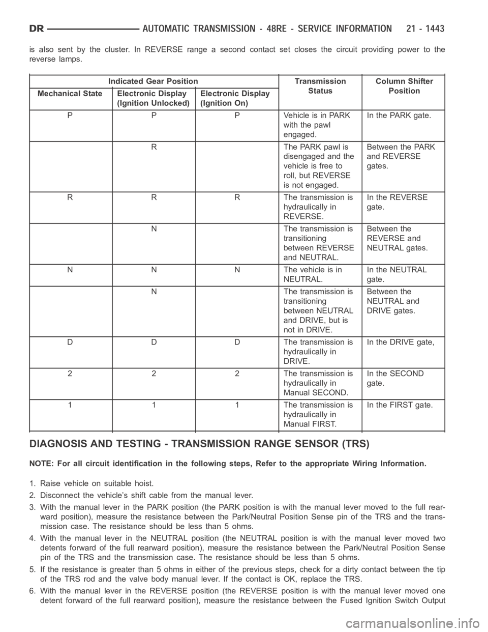
is also sent by the cluster. In REVERSE range a second contact set closes thecircuit providing power to the
reverse lamps.
Indicated Gear Position Transmission
StatusColumn Shifter
Position
Mechanical State Electronic Display
(Ignition Unlocked)Electronic Display
(Ignition On)
P P P Vehicle is in PARK
with the pawl
engaged.In the PARK gate.
R The PARK pawl is
disengaged and the
vehicle is free to
roll, but REVERSE
is not engaged.Between the PARK
and REVERSE
gates.
R R R The transmission is
hydraulically in
REVERSE.In the REVERSE
gate.
N The transmission is
transitioning
between REVERSE
and NEUTRAL.Between the
REVERSE and
NEUTRAL gates.
N N N The vehicle is in
NEUTRAL.In the NEUTRAL
gate.
N The transmission is
transitioning
between NEUTRAL
and DRIVE, but is
not in DRIVE.Between the
NEUTRAL and
DRIVE gates.
D D D The transmission is
hydraulically in
DRIVE.In the DRIVE gate,
2 2 2 The transmission is
hydraulically in
Manual SECOND.In the SECOND
gate.
1 1 1 The transmission is
hydraulically in
Manual FIRST.In the FIRST gate.
DIAGNOSIS AND TESTING - TRANSMISSION RANGE SENSOR (TRS)
NOTE: For all circuit identification in the following steps, Refer to the appropriate Wiring Information.
1. Raise vehicle on suitable hoist.
2. Disconnect the vehicle’s shift cable from the manual lever.
3. With the manual lever in the PARK position (the PARK position is with the manual lever moved to the full rear-
ward position), measure the resistance between the Park/Neutral PositionSensepinoftheTRSandthetrans-
mission case. The resistance should be less than 5 ohms.
4. With the manual lever in the NEUTRAL position (the NEUTRAL position is with the manual lever moved two
detents forward of the full rearward position), measure the resistance between the Park/Neutral Position Sense
pin of the TRS and the transmission case. The resistance should be less than5ohms.
5. If the resistance is greater than 5 ohms in either of the previous steps, check for a dirty contact between the tip
of the TRS rod and the valve body manual lever. If the contact is OK, replace the TRS.
6. With the manual lever in the REVERSE position (the REVERSE position is with the manual lever moved one
detent forward of the full rearward position), measure the resistance between the Fused Ignition Switch Output
Page 4025 of 5267
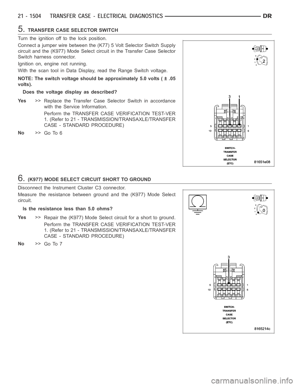
5.TRANSFER CASE SELECTOR SWITCH
Turn the ignition off to the lock position.
Connect a jumper wire between the (K77) 5 Volt Selector Switch Supply
circuit and the (K977) Mode Select circuit in the Transfer Case Selector
Switch harness connector.
Ignition on, engine not running.
With the scan tool in Data Display, read the Range Switch voltage.
NOTE: The switch voltage should be approximately 5.0 volts ( ± .05
volts).
Does the voltage display as described?
Ye s>>
Replace the Transfer Case Selector Switch in accordance
with the Service Information.
Perform the TRANSFER CASE VERIFICATION TEST-VER
1. (Refer to 21 - TRANSMISSION/TRANSAXLE/TRANSFER
CASE - STANDARD PROCEDURE)
No>>
Go To 6
6.(K977) MODE SELECT CIRCUIT SHORT TO GROUND
Disconnect the Instrument Cluster C3 connector.
Measure the resistance between ground and the (K977) Mode Select
circuit.
Is the resistance less than 5.0 ohms?
Ye s>>
Repair the (K977) Mode Select circuit for a short to ground.
Perform the TRANSFER CASE VERIFICATION TEST-VER
1. (Refer to 21 - TRANSMISSION/TRANSAXLE/TRANSFER
CASE - STANDARD PROCEDURE)
No>>
Go To 7
Page 4058 of 5267
When Monitored:
Ignition on, battery voltage between 9.0 and 16.0 volts.
Set Condition:
The TIPM detects no voltage on the Transfer Case Motor Control circuit for aperiod greater than 2 seconds,
when voltage should be present.
Possible Causes
(T101) SHIFT MOTOR CONTROL A CIRCUIT OPEN
(T102) SHIFT MOTOR CONTROL B CIRCUIT OPEN
SHIFT MOTOR/MODE SENSOR ASSEMBLY
TOTALLY INTEGRATED POWER MODULE (TIPM)
Diagnostic Test
1.DTC IS ACTIVE
Ignition on, engine not running.
With the scan tool, read TIPM DTCs.
Move the Shift control to each position, while monitoring the Data Displayon the scan tool.
Does the DTC reset?
Ye s>>
Go to 2
No>>
Go to 8
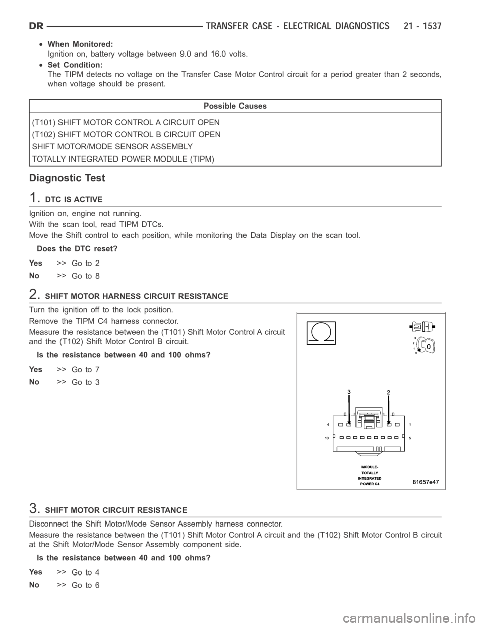
2.SHIFT MOTOR HARNESS CIRCUIT RESISTANCE
Turn the ignition off to the lock position.
Remove the TIPM C4 harness connector.
Measure the resistance between the (T101) Shift Motor Control A circuit
and the (T102) Shift Motor Control B circuit.
Is the resistance between 40 and 100 ohms?
Ye s>>
Go to 7
No>>
Go to 3
3.SHIFT MOTOR CIRCUIT RESISTANCE
Disconnect the Shift Motor/Mode Sensor Assembly harness connector.
Measure the resistance between the (T101) Shift Motor Control A circuit and the (T102) Shift Motor Control B circuit
at the Shift Motor/Mode Sensor Assembly component side.
Is the resistance between 40 and 100 ohms?
Ye s>>
Go to 4
No>>
Go to 6
Page 4848 of 5267
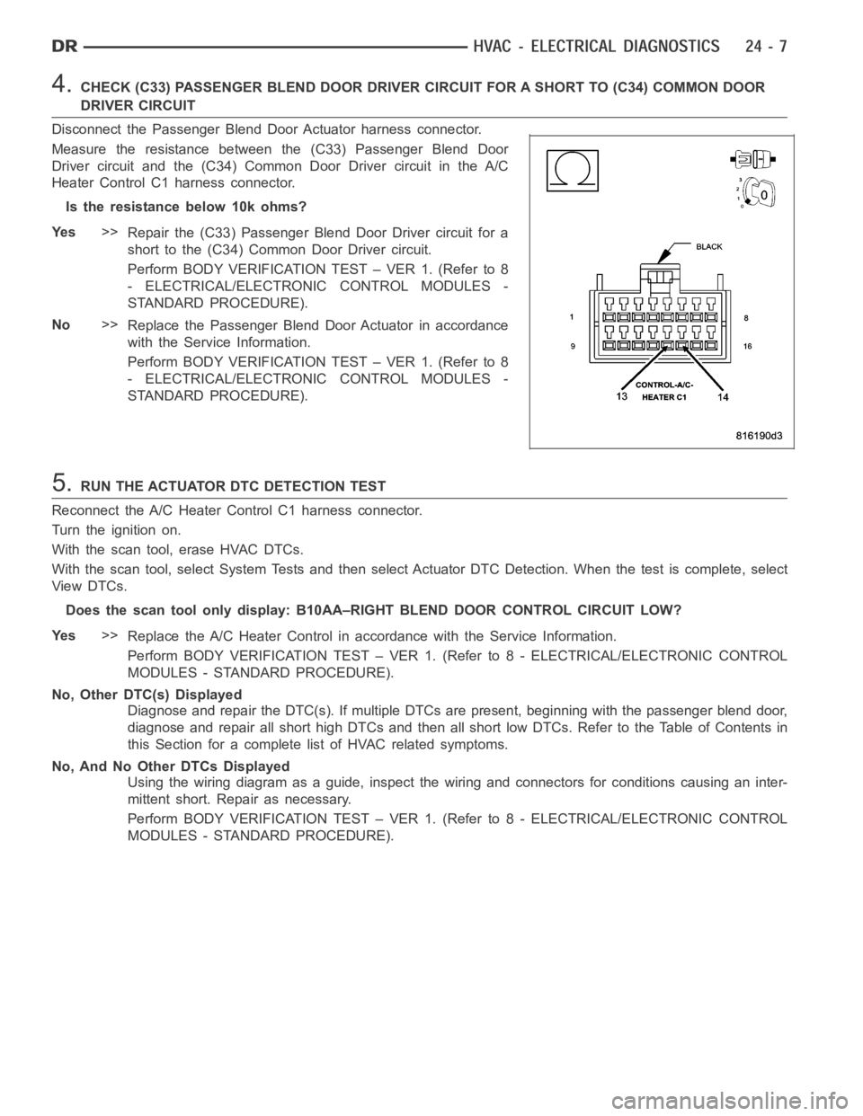
4.CHECK (C33) PASSENGER BLEND DOOR DRIVER CIRCUIT FOR A SHORT TO (C34) COMMONDOOR
DRIVER CIRCUIT
Disconnect the Passenger Blend Door Actuator harness connector.
Measure the resistance between the (C33) Passenger Blend Door
Driver circuit and the (C34) Common Door Driver circuit in the A/C
Heater Control C1 harness connector.
Istheresistancebelow10kohms?
Ye s>>
Repair the (C33) Passenger Blend Door Driver circuit for a
short to the (C34) Common Door Driver circuit.
Perform BODY VERIFICATION TEST – VER 1. (Refer to 8
- ELECTRICAL/ELECTRONIC CONTROL MODULES -
STANDARD PROCEDURE).
No>>
Replace the Passenger Blend Door Actuator in accordance
with the Service Information.
Perform BODY VERIFICATION TEST – VER 1. (Refer to 8
- ELECTRICAL/ELECTRONIC CONTROL MODULES -
STANDARD PROCEDURE).
5.RUN THE ACTUATOR DTC DETECTION TEST
Reconnect the A/C Heater Control C1 harness connector.
Turn the ignition on.
With the scan tool, erase HVAC DTCs.
With the scan tool, select System Tests and then select Actuator DTC Detection. When the test is complete, select
View DTCs.
Does the scan tool only display: B10AA–RIGHT BLEND DOOR CONTROL CIRCUIT LOW?
Ye s>>
Replace the A/C Heater Control in accordance with the Service Information.
Perform BODY VERIFICATION TEST – VER 1. (Refer to 8 - ELECTRICAL/ELECTRONIC CONTROL
MODULES - STANDARD PROCEDURE).
No, Other DTC(s) Displayed
Diagnose and repair the DTC(s). If multiple DTCs are present, beginning with the passenger blend door,
diagnose and repair all short high DTCs and then all short low DTCs. Refer tothe Table of Contents in
this Section for a complete list of HVAC related symptoms.
No, And No Other DTCs Displayed
Using the wiring diagram as a guide, inspect the wiring and connectors for conditions causing an inter-
mittent short. Repair as necessary.
Perform BODY VERIFICATION TEST – VER 1. (Refer to 8 - ELECTRICAL/ELECTRONIC CONTROL
MODULES - STANDARD PROCEDURE).
Page 4850 of 5267
Theory of Operation
The A/C Heater Control drives the Passenger Blend Door Actuator via the (C33) Passenger Blend Door Driver cir-
cuit and the (C34) Common Door Driver circuit. All of the door actuators share the (C34) Common Door Driver
circuit. Inside the A/C Heater Control, each door actuator has its own unique driver, but all share a single common
door driver circuit. Due to the shared circuitry similar DTCs can set at thesame time for multiple actuators depend-
ing upon the type of short, its location, and the direction the actuator is moving when the short is present.
When Monitored:
When the Actuator DTC Detection Test is executed.
Set Condition:
If the (C33) Passenger Blend Door Driver circuit is shorted to voltage.
Possible Causes
(C33) PASSENGER BLEND DOOR DRIVERCIRCUIT SHORTED TO VOLTAGE
A/C HEATER CONTROL
Diagnostic Test
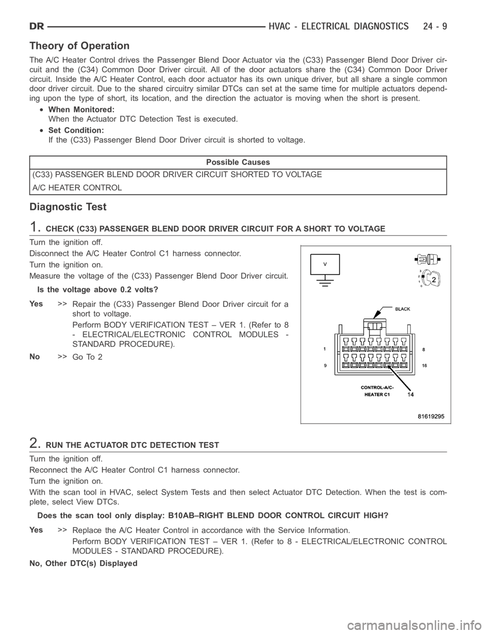
1.CHECK (C33) PASSENGER BLEND DOOR DRIVER CIRCUIT FOR A SHORT TO VOLTAGE
Turn the ignition off.
Disconnect the A/C Heater Control C1 harness connector.
Turn the ignition on.
Measure the voltage of the (C33) Passenger Blend Door Driver circuit.
Is the voltage above 0.2 volts?
Ye s>>
Repair the (C33) Passenger Blend Door Driver circuit for a
short to voltage.
Perform BODY VERIFICATION TEST – VER 1. (Refer to 8
- ELECTRICAL/ELECTRONIC CONTROL MODULES -
STANDARD PROCEDURE).
No>>
Go To 2
2.RUN THE ACTUATOR DTC DETECTION TEST
Turn the ignition off.
Reconnect the A/C Heater Control C1 harness connector.
Turn the ignition on.
With the scan tool in HVAC, select System Tests and then select Actuator DTCDetection. When the test is com-
plete, select View DTCs.
Does the scan tool only display: B10AB–RIGHT BLEND DOOR CONTROL CIRCUIT HIGH?
Ye s>>
Replace the A/C Heater Control in accordance with the Service Information.
Perform BODY VERIFICATION TEST – VER 1. (Refer to 8 - ELECTRICAL/ELECTRONIC CONTROL
MODULES - STANDARD PROCEDURE).
No, Other DTC(s) Displayed
Page 4851 of 5267
Diagnose and repair the DTC(s). If multiple DTCs are present, beginning with the passenger blend door,
diagnose and repair all short high DTCs and then all short low DTCs. Refer tothe Table of Contents in
this Section for a complete list of HVAC related symptoms.
No, And No Other DTCs Displayed
Using the wiring diagram as a guide, inspect the wiring and connectors for conditions causing an inter-
mittent short. Repair as necessary.
Perform BODY VERIFICATION TEST – VER 1. (Refer to 8 - ELECTRICAL/ELECTRONIC CONTROL
MODULES - STANDARD PROCEDURE).