remove DODGE SPRINTER 2007 2.G User Guide
[x] Cancel search | Manufacturer: DODGE, Model Year: 2007, Model line: SPRINTER, Model: DODGE SPRINTER 2007 2.GPages: 393, PDF Size: 7.61 MB
Page 117 of 393
116 Controls in detailDriving and parking
3
Stopping the engine
\1Apply handbrake (\2page 115).
\1Move selector lever to P.
\1Turn key to position 0 (\2page 67) in
the ignition lock and remove it.
The immobilizer is activated.\1Secure the vehicle at the front axle if
unloaded and at the rear axle if loaded,
e.g. using a chock (\2page 303).
Drinking and drivingSteering
!
CAUTION
If the coolant temperature is raised,
e.g. following driving in mountainous
terrain, run the engine at idling speed
for a further 1 or 2 minutes before you
switch off the engine. This allows the
coolant temperature to return to nor-
mal again.
iWhen parking on steep uphill or down-
hill gradients, turn the front wheels to-
wards the curb.iYou can only remove the key from the
ignition lock when the selector lever is
in positionP.
General driving tipsWarning
G
Drinking and driving and/or taking drugs
and driving are very dangerous combina-
tions. Even a small amount of alcohol or
drugs can affect your reflexes, perceptions
and judgment. The possibility of a serious or
even fatal accident is sharply increased
when you drink or take drugs and drive.
Never drink or take drugs and drive or allow
anyone to drive after drinking or taking
drugs.
Warning
G
There is no power-steering assistance when
the engine is not running.
You will need to use significantly more force
to steer and could therefore lose control of
the vehicle and cause an accident.
Never switch off the engine while driving.!
CAUTION
Do not hold the steering wheel in its
end positions for longer than neces-
sary (e.g. when turning or maneuver-
ing).
The hydraulic pump can be damaged
by the increased temperature of the
hydraulic fluid.
Page 118 of 393
117 Controls in detail
Driving and parking
3
Overrun cut-off
The gasoline/diesel supply is cut off if the
driver's foot is completely removed from
the accelerator pedal when the engine is
overrunning at engine speeds outside of
the idling control range.
Driving in wet conditionsDriving on flooded roads
If you are forced to drive on stretches of
road on which water has collected, please
note that:
\4the water level must not reach above
the lower edge of the front bumper
\4the maximum speed at which you may
drive is walking speed
Tires
The tires are particularly important for the
operating and road safety of the vehicle.
You should therefore check the pressure,
tread and condition of the tires on a regular
basis.A tire dealer, a qualified specialist work-
shop or any authorized Sprinter Dealer will
be able to provide further information re-
garding the:
\4list of recommended makes of tire
\4tire load-bearing capacity (LI Load
Index)
\4maximum tire speed (SI Speed Index)
\4tire age
\4causes and consequences of tire wear
\4measures to be taken in the event of
tire damage
\4tire types for certain regions, areas of
operation or conditions of vehicle use
\4interchangeability of tires, etc.
Modifications to the brake system or
wheels are not permissible, nor is the use
of spacer plates or brake dust shields. Any
such modifications will invalidate the vehi-
cle’s general operating permit.Warning
G
The vehicle may hydroplane despite having
adequate tire tread depth and being driven
at low speeds, depending on the depth of
water on the road surface.
For this reason, avoid tire ruts and brake
carefully.
!
CAUTION
Note that vehicles in front or oncoming
vehicles create waves.
This may mean that the maximum per-
mitted water depth is exceeded.
These notes must be observed to avoid
the risk of engine damage.
Page 122 of 393
121 Controls in detail
Automatic transmission
3
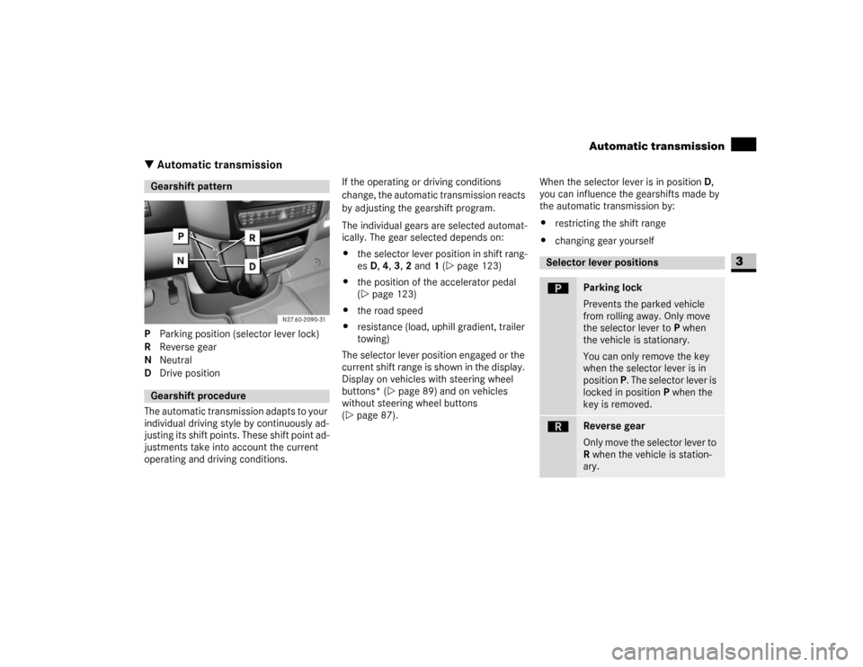
\3 Automatic transmissionP Parking position (selector lever lock)
R Reverse gear
N Neutral
D Drive position
The automatic transmission adapts to your
individual driving style by continuously ad-
justing its shift points. These shift point ad-
justments take into account the current
operating and driving conditions.If the operating or driving conditions
change, the automatic transmission reacts
by adjusting the gearshift program.
The individual gears are selected automat-
ically. The gear selected depends on:
\4the selector lever position in shift rang-
es D, 4, 3, 2 and 1 (\2page 123)
\4the position of the accelerator pedal
(\2page 123)
\4the road speed
\4resistance (load, uphill gradient, trailer
towing)
The selector lever position engaged or the
current shift range is shown in the display.
Display on vehicles with steering wheel
buttons* (\2page 89) and on vehicles
without steering wheel buttons
(\2page 87).When the selector lever is in position D,
you can influence the gearshifts made by
the automatic transmission by:
\4restricting the shift range
\4changing gear yourselfGearshift patternGearshift procedure
Selector lever positionsì
Parking lock
Prevents the parked vehicle
from rolling away. Only move
the selector lever to P when
the vehicle is stationary.
You can only remove the key
when the selector lever is in
position P. The selector lever is
locked in position P when the
key is removed.
í
Reverse gear
Only move the selector lever to
R when the vehicle is station-
ary.
Page 131 of 393
130 Controls in detailTempmatic
3
Tempmatic is only operational while the
engine is running. You can use Tempmatic
to regulate or control the temperature au-
tomatically. The vehicle is either heated or
cooled, depending on the temperature se-
lected and the outside temperature.
The combination filter removes most dust
particles, pollen and unpleasant odors
from the outside air.
The interval for replacing the filter depends
on environmental factors, e.g. high air pol-
lution. The interval may be shorter than
that indicated in the Service Booklet.
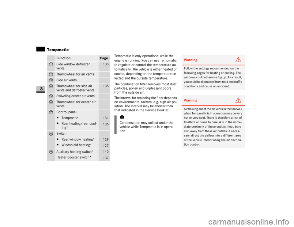
Function
Page
1
Side window defroster
vents
135
2
Thumbwheel for air vents
3
Side air vents
4
Thumbwheel for side air
vents and defroster vents
135
5
Swiveling center air vents
6
Thumbwheel for center air
vents
7
Control panel\4Tempmatic
\4Rear heating/rear cool-
ing*
131
136
8
Switch\4Rear window heating*
\4Windshield heating*
128
127
9
Auxiliary heating switch*
Heater booster switch*
140
137
iCondensation may collect under the
vehicle while Tempmatic is in opera-
tion.
Warning
G
Follow the settings recommended on the
following pages for heating or cooling. The
windows could otherwise fog up. As a result,
you could be distracted from road and traffic
conditions and cause an accident.Warning
G
Air flowing out of the air vents in the footwell
when Tempmatic is in operation may be very
hot or very cold. There is therefore a risk of
frostbite or burns to bare skin in the imme-
diate proximity of these outlets. Keep bare
skin away from these air outlets. If neces-
sary, direct the airflow into a different area
of the vehicle interior using the air distribu-
tion control.
Page 145 of 393
144 Controls in detailOpen air
3
\3 Open airYou can open and close the side windows
electrically.
The switches for all side windows are locat-
ed on the door control panel.
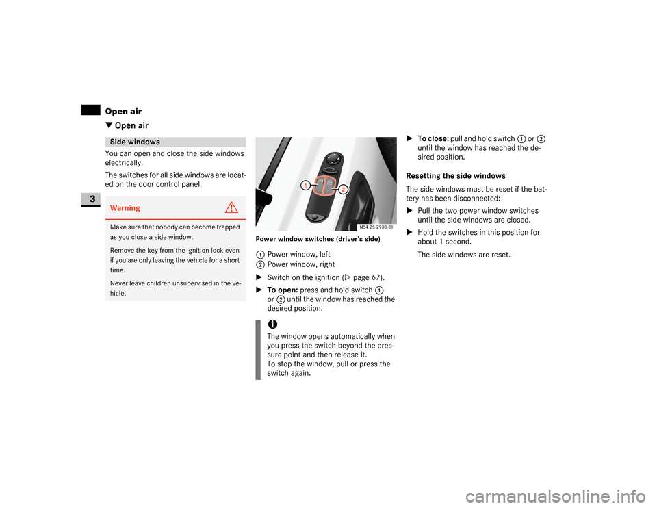
Power window switches (driver’s side)1Power window, left
2Power window, right
\1Switch on the ignition (\2page 67).
\1To open: press and hold switch1
or2 until the window has reached the
desired position.\1To close: pull and hold switch1 or2
until the window has reached the de-
sired position.
Resetting the side windows
The side windows must be reset if the bat-
tery has been disconnected:
\1Pull the two power window switches
until the side windows are closed.
\1Hold the switches in this position for
about 1 second.
The side windows are reset.
Side windowsWarning
G
Make sure that nobody can become trapped
as you close a side window.
Remove the key from the ignition lock even
if you are only leaving the vehicle for a short
time.
Never leave children unsupervised in the ve-
hicle.
iThe window opens automatically when
you press the switch beyond the pres-
sure point and then release it.
To stop the window, pull or press the
switch again.
Page 146 of 393
145 Controls in detail
Open air
3
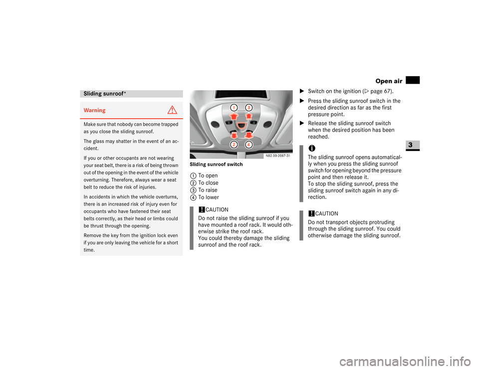
Sliding sunroof switch1To open
2To close
3To raise
4To lower\1Switch on the ignition (\2page 67).
\1Press the sliding sunroof switch in the
desired direction as far as the first
pressure point.
\1Release the sliding sunroof switch
when the desired position has been
reached.
Sliding sunroof*Warning
G
M a k e s u r e t h a t n o b o d y c a n b e c o m e t r a p p e d
as you close the sliding sunroof.
The glass may shatter in the event of an ac-
cident.
If you or other occupants are not wearing
your seat belt, there is a risk of being thrown
out of the opening in the event of the vehicle
overturning. Therefore, always wear a seat
belt to reduce the risk of injuries.
In accidents in which the vehicle overturns,
there is an increased risk of injury even for
occupants who have fastened their seat
belts correctly, as their head or limbs could
be thrust through the opening.
Remove the key from the ignition lock even
if you are only leaving the vehicle for a short
time.
!
CAUTION
Do not raise the sliding sunroof if you
have mounted a roof rack. It would oth-
erwise strike the roof rack.
You could thereby damage the sliding
sunroof and the roof rack.
iThe sliding sunroof opens automatical-
ly when you press the sliding sunroof
switch for opening beyond the pressure
point and then release it.
To stop the sliding sunroof, press the
sliding sunroof switch again in any di-
rection.!
CAUTION
Do not transport objects protruding
through the sliding sunroof. You could
otherwise damage the sliding sunroof.
Page 147 of 393
146 Controls in detailOpen air
3
Resetting the sliding sunroof
The sliding sunroof must be reset after:
\4the sunroof has been closed manually
using the emergency operation key
(\2page 304)
\4the sunroof has opened with a jerk
\4a malfunction
\1Switch on the ignition (\2page 67).
\1Press the sliding sunroof switch in the
direction of arrow2 (\2page 145).
\1Wait until the sliding sunroof is closed
and then keep the sliding sunroof
switch pressed for approximately
3seconds.
The sliding sunroof is reset.The roof ventilator can be used to ventilate
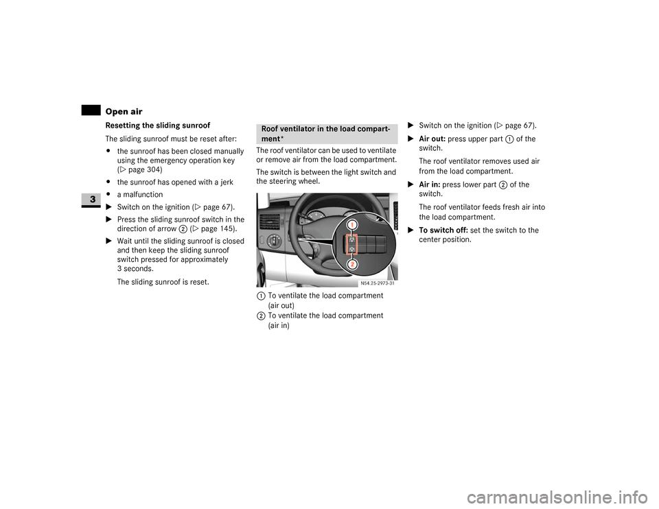
or remove air from the load compartment.
The switch is between the light switch and
the steering wheel.
1To ventilate the load compartment
(air out)
2To ventilate the load compartment
(air in)\1Switch on the ignition (\2page 67).
\1Air out: press upper part 1 of the
switch.
The roof ventilator removes used air
from the load compartment.
\1Air in: press lower part 2 of the
switch.
The roof ventilator feeds fresh air into
the load compartment.
\1To switch off: set the switch to the
center position.
Roof ventilator in the load compart-
ment*
N54.25-2929-31
Page 162 of 393
161 Controls in detail
Transporting
3
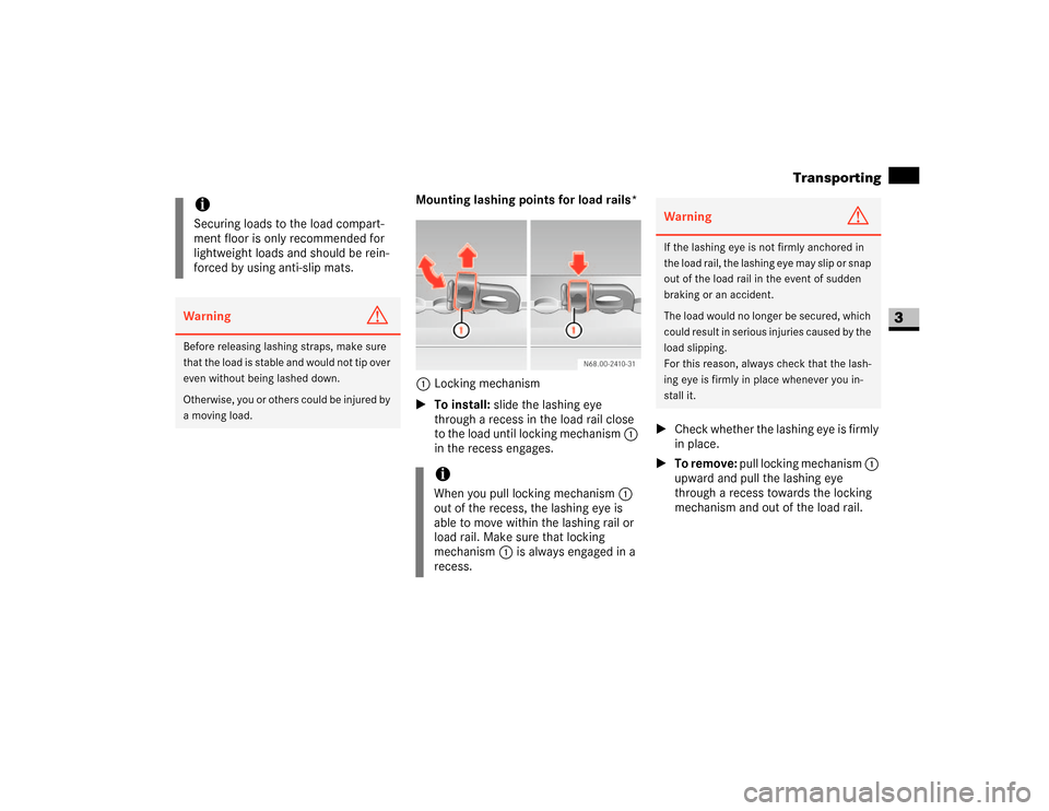
Mounting lashing points for load rails*
1Locking mechanism
\1To install: slide the lashing eye
through a recess in the load rail close
to the load until locking mechanism 1
in the recess engages.\1Check whether the lashing eye is firmly
in place.
\1To remove: pull locking mechanism 1
upward and pull the lashing eye
through a recess towards the locking
mechanism and out of the load rail.
iSecuring loads to the load compart-
ment floor is only recommended for
lightweight loads and should be rein-
forced by using anti-slip mats.Warning
G
Before releasing lashing straps, make sure
that the load is stable and would not tip over
even without being lashed down.
Otherwise, you or others could be injured by
a moving load.
iWhen you pull locking mechanism1
out of the recess, the lashing eye is
able to move within the lashing rail or
load rail. Make sure that locking
mechanism1 is always engaged in a
recess.
Warning
G
If the lashing eye is not firmly anchored in
the load rail, the lashing eye may slip or snap
out of the load rail in the event of sudden
braking or an accident.
The load would no longer be secured, which
could result in serious injuries caused by the
load slipping.
For this reason, always check that the lash-
ing eye is firmly in place whenever you in-
stall it.
Page 169 of 393
168 Controls in detailFeatures
3
\1Place the container in cup holder5.
\1Press clamping arm6 onto the con-
tainer.
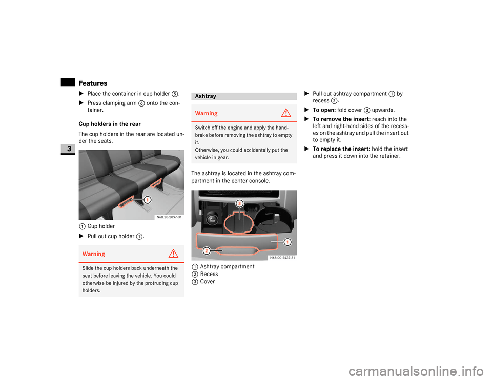
Cup holders in the rear
The cup holders in the rear are located un-
der the seats.
1Cup holder
\1Pull out cup holder1.The ashtray is located in the ashtray com-
partment in the center console.
1Ashtray compartment
2Recess
3Cover\1Pull out ashtray compartment1 by
recess2.
\1To open: fold cover3 upwards.
\1To remove the insert: reach into the
left and right-hand sides of the recess-
es on the ashtray and pull the insert out
to empty it.
\1To replace the insert: hold the insert
and press it down into the retainer.Warning
G
Slide the cup holders back underneath the
seat before leaving the vehicle. You could
otherwise be injured by the protruding cup
holders.
AshtrayWarning
G
Switch off the engine and apply the hand-
brake before removing the ashtray to empty
it.
Otherwise, you could accidentally put the
vehicle in gear.
Page 170 of 393
169 Controls in detail
Features
3
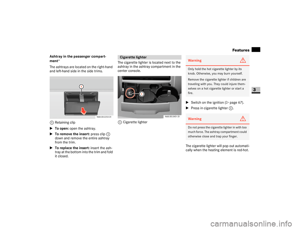
Ashtray in the passenger compart-
ment*
The ashtrays are located on the right-hand
and left-hand side in the side trims.
1Retaining clip
\1To open: open the ashtray.
\1To remove the insert: press clip1
down and remove the entire ashtray
from the trim.
\1To replace the insert: insert the ash-
tray at the bottom into the trim and fold
it closed.The cigarette lighter is located next to the
ashtray in the ashtray compartment in the
center console.
1Cigarette lighter\1Switch on the ignition (\2page 67).
\1Press in cigarette lighter 1.
The cigarette lighter will pop out automati-
cally when the heating element is red-hot.
Cigarette lighter
Warning
G
Only hold the hot cigarette lighter by its
knob. Otherwise, you may burn yourself.
Remove the cigarette lighter if children are
traveling with you. They could injure them-
selves on a hot cigarette lighter or start a
fire.Warning
G
Do not press the cigarette lighter in with too
much force. The ashtray compartment could
otherwise close and trap your finger.