engine DODGE STRATUS COUPE 2005 2.G Manual Online
[x] Cancel search | Manufacturer: DODGE, Model Year: 2005, Model line: STRATUS COUPE, Model: DODGE STRATUS COUPE 2005 2.GPages: 396
Page 280 of 396
WARNING!
²When working near the radiator cooling fan, dis-
connect the fan motor lead or turn the ignition key
to the OFF position. The fan is temperature con-
trolled and can start at any time the ignition key is
in the ON position.
²You or others can be badly burned by hot coolant
or steam from your radiator. If you see or hear
steam coming from under the hood, don't open
the hood until the radiator has had time to cool.
Never try to open a cooling system pressure cap
when the radiator is hot.
JUMP-STARTING THE ENGINE
If the engine cannot be started because the battery is
weak or dead, the battery from another vehicle can be
used with booster cables to start the engine.
WARNING!
When using jumper cables to start a vehicle, follow
procedures exactly and exercise extreme caution.
CAUTION!
Do not try to start your vehicle by pushing or towing.
Vehicles equipped with an automatic transaxle can-
not be started this way. Pushing or towing a vehicle
equipped with a manual transaxle may overheat and
damage the catalytic converter. Also, there is a
greater risk of an accident when a vehicle is being
pushed or towed.
1. Remove any metal jewelry such as watch bands or
bracelets that might make an inadvertent electrical con-
tact.
2. Position the vehicles close enough together so the
booster cables can reach, but be sure the vehicles aren't
touching each other. If they are, it could cause a ground
280 EMERGENCIES
Page 283 of 396
6. Connect one end of the other jumper cable to the
negative (-) terminal of the booster battery (B), and the
other end to the engine block of the vehicle with the
discharged battery (A) at the point farthest from the
battery.WARNING!
²Be sure to observe the connecting sequence of¬
!!®!¯.
²Make sure that the connection¯is made to the
engine properly. If the connection is directly made
to the negative side of the battery, the flammable
gases generated from the battery might catch fire
and explode.
²When connecting the booster cable, do not con-
nect the positive (+) cable to the negative (-)
terminal. Otherwise sparks might cause explosion
of the battery.
²Use care not to have the booster cable caught in
the cooling fan or other rotating parts in the
engine compartment.
7. Start the engine in the vehicle which has the booster
battery, let the engine idle a few minutes, then start the
engine in the vehicle with the discharged battery.
8. After the engine is started, disconnect the cables in the
reverse order.
EMERGENCIES 283
8
Page 284 of 396
WARNING!
²Charging the battery installed in the vehicle
might cause the battery to catch fire and explode.
Or, damage to the vehicle could result. If it has to
be charged in that condition for unavoidable
reasons, disconnect the vehicle side negative lead.
²Keep sparks, cigarettes and flames away from the
battery because the battery may produce an explosion.
²Use adequate ventilation when charging or using
the battery in an enclosed space.
²Remove all the caps before charging the battery.
²Electrolyte (battery acid) is corrosive diluted sulfuric
acid. If electrolyte comes in contact with your hands,
eyes, clothes, or the painted surface of your vehicle,
thoroughly flush with water. If electrolyte gets in
your eyes, flush them thoroughly with water imme-
diately, and get prompt medical attention.
WARNING!
²Always wear protective clothing and goggles
when working near the battery.
²Keep the battery out of the reach of children.
If your vehicle has anti-lock brakes
If the vehicle is driven without sufficient battery charge,
after the engine has been started by using booster cables,
the engine may misfire. This can cause the anti-lock
braking system warning light to blink on and off. This is
a result of insufficient battery voltage; it is not a malfunc-
tion of the brake system. If this happens, fully charge the
battery before driving.
TOWING
When towing your vehicle, all state and local regulations for
towing must be followed. Incorrect towing equipment could
damage your vehicle. When towing is required, contact a
professional towing service and make sure that flat bed type,
dolly type or wheel lift type towing equipment is used. Do
not attempt to be towed by another vehicle with a rope using
the tie-down hooks.
284 EMERGENCIES
Page 287 of 396
Fuse block
To prevent damage to the electrical system due to short-
circuiting or overloading, each individual circuit is pro-
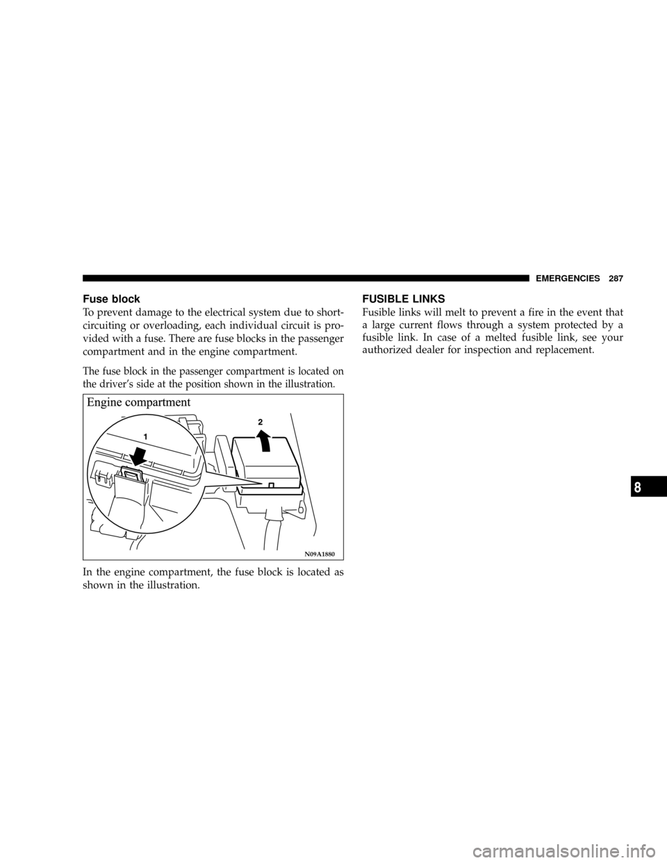
vided with a fuse. There are fuse blocks in the passenger
compartment and in the engine compartment.
The fuse block in the passenger compartment is located on
the driver's side at the position shown in the illustration.
In the engine compartment, the fuse block is located as
shown in the illustration.
FUSIBLE LINKS
Fusible links will melt to prevent a fire in the event that
a large current flows through a system protected by a
fusible link. In case of a melted fusible link, see your
authorized dealer for inspection and replacement.
N09A1880
EMERGENCIES 287
8
Page 289 of 396
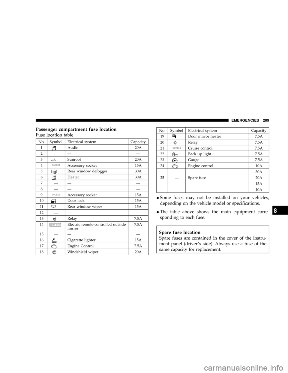
Passenger compartment fuse location
Fuse location table
No. Symbol Electrical system Capacity
1
Audio 20A
2
ÐÐÐ
3
Sunroof 20A
4
SOCKETAccessory socket 15A
5
Rear window defogger 30A
6
Heater 30A
7
ÐÐÐ
8
ÐÐÐ
9
SOCKETAccessory socket 15A
10
Door lock 15A
11
Rear window wiper 15A
12
ÐÐÐ
13
Relay 7.5A
14
R/C MIRElectric remote-controlled outside
mirror7.5A
15
ÐÐÐ
16
Cigarette lighter 15A
17
Engine Control 7.5A
18
Windshield wiper 20A
No. Symbol Electrical system Capacity
19
Door mirror heater 7.5A
20
Relay 7.5A
21
CRUISECruise control 7.5A
22
Back up light 7.5A
23
Gauge 7.5A
24
Engine control 10A
30A
25
ÐSpare fuse 20A
15A
10A
ISome fuses may not be installed on your vehicles,
depending on the vehicle model or specifications.
IThe table above shows the main equipment corre-
sponding to each fuse.
Spare fuse location
Spare fuses are contained in the cover of the instru-
ment panel (driver 's side). Always use a fuse of the
same capacity for replacement.
EMERGENCIES 289
8
Page 290 of 396
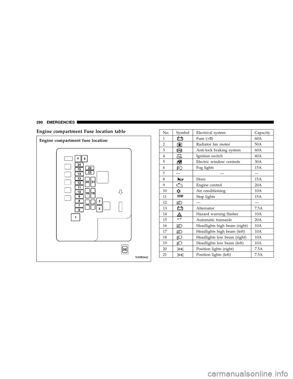
Engine compartment Fuse location tableNo. Symbol Electrical system Capacity
1
Fuse (+B) 60A
2
Radiator fan motor 50A
3
Anti-lock braking system 60A
4
Ignition switch 40A
5
Electric window controls 30A
6
Fog lights 15A
7Ð Ð Ð
8
Horn 15A
9
Engine control 20A
10
Air conditioning 10A
11
Stop lights 15A
12
ÐÐ
13
Alternator 7.5A
14
Hazard warning flasher 10A
15
Automatic transaxle 20A
16
Headlights high beam (right) 10A
17
Headlights high beam (left) 10A
18
Headlights low beam (right) 10A
19
Headlights low beam (left) 10A
20
Position lights (right) 7.5A
21
Position lights (left) 7.5AN29B2642
Engine compartment fuse location
290 EMERGENCIES
Page 309 of 396

MAINTENANCE
CONTENTS
mView of engine compartment..............311
mService precautions.....................312
mEmission-control system maintenance.......313
mEmissions Testing......................314
mOnboard Diagnostic System (OBD II)........314
mReplacement Parts......................315
NFuel system (tank, filler tube, connections,
and fuel tank filler cap).................315
NFuel hoses...........................315
NAir cleaner filter......................316
NEvaporative emission control system
(except evaporative emission canister).......316
NSpark plugs..........................317
NIgnition cables........................317NDistributor cap and rotor................317
mGeneral maintenance....................318
NEngine oil and oil filter..................318
mEngine coolant.........................322
NTo check the coolant level................322
NTo add coolant........................322
mBrake fluid...........................323
mClutch fluid (manual transaxle)............324
NTo check the clutch fluid.................324
NTo replace the fluid....................324
mBattery..............................325
NDuring cold weather...................327
9
Page 311 of 396
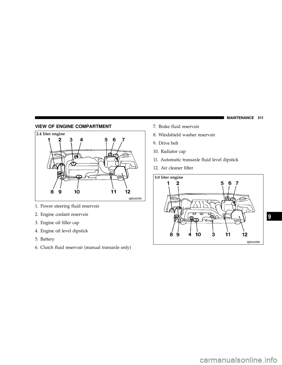
VIEW OF ENGINE COMPARTMENT
1. Power steering fluid reservoir
2. Engine coolant reservoir
3. Engine oil filler cap
4. Engine oil level dipstick
5. Battery
6. Clutch fluid reservoir (manual transaxle only)7. Brake fluid reservoir
8. Windshield washer reservoir
9. Drive belt
10. Radiator cap
11. Automatic transaxle fluid level dipstick
12. Air cleaner filter
Q02A2510
2.4 liter engine
Q02A2520
3.0 liter engine
MAINTENANCE 311
9
Page 312 of 396
NOTE: The Scheduled Maintenance Charts are located
in the rear of this maintenance section. Always refer to
the schedules for proper service intervals.
SERVICE PRECAUTIONS
Adequate care of your vehicle at regular intervals serves
to preserve the value and appearance as long as possible.
Some maintenance items can be performed by the owner,
while others should be done only by an authorized
dealer.
This section describes only those items which can be
performed by the owner. In the event a malfunction or
other problem is discovered, have it corrected by an
authorized dealer.
This section contains information on inspection mainte-
nance procedures that you can do yourself, if you so
desire. Follow the instructions and precautions for each
of the various procedures.
WARNING!
²When checking or servicing the inside of the
engine compartment, be sure the engine is
stopped and has had a chance to cool down.
²If it is necessary to do work in the engine com-
partment with the engine running, be especially
careful that your clothing, hair, etc. does not
become caught by the fan, drive belts, or other
moving parts.
312 MAINTENANCE
Page 313 of 396
WARNING!
²The fan may turn on automatically even if the
engine is not running; turn the ignition key to the
ªLOCKº position and remove the key to ensure
safety while you work in the engine compartment.
²Do not smoke, or allow open flames around fuel
or the battery. The fumes are flammable.
²Be extremely cautious when working around the
battery. It contains poisonous and corrosive sulfu-
ric acid.
²Do not get under your vehicle with just the car's
jack supporting it.
Always use properly rated automotive jack
stands.
²Improper handling of components and materials
used in the vehicle can endanger your personal
safety. Consult an authorized dealer if you have
questions.
EMISSION-CONTROL SYSTEM MAINTENANCE
Your vehicle is equipped with an emission-control sys-
tem which satisfies all requirements of the U.S. Environ-
mental Protection Agency. The emission-control system
consists of:
(1) a positive crankcase ventilation system
(2) an evaporative emission-control system
(3) an exhaust emission- control system.
The9Scheduled9maintenance services listed must be
performed at the times or mileages specified to assure the
continued proper functioning of the emission-control
system. These, and all other ªGeneralº maintenance
services included in this manual, should be performed to
provide the best vehicle performance and reliability.
More frequent maintenance may be needed for vehicles
driven under severe operating conditions such as dusty
areas and frequent start and stop driving.
In order to assure the proper function of the emission-
control system, it is recommended that you have your
vehicle inspected and maintained by an authorized
dealer in accordance with the schedule in this manual.
Inspection and service should also be performed any
time a malfunction is suspected.
MAINTENANCE 313
9